


Wideband noise generator
#wideband
#noise generator
#rf noise
#reverse-biased diode
#low-impedance
#rf circuit
#signal generation
#electronic noise
#broadband

Description: This circuit generates wideband RF noise utilizing a reverse-biased diode, featuring a low-impedance output. It can be employed to align receivers for optimal performance.
The circuit primarily consists of a reverse-biased diode, which serves as the core component for generating RF noise. When reverse-biased, the diode operates in a breakdown region, producing noise across a wide frequency range. This characteristic is essential for applications requiring random noise signals, such as in the alignment of radio receivers.
The low-impedance output is crucial for interfacing with other circuit components, ensuring that the generated noise can be effectively coupled to the receiver circuitry without significant signal loss. This configuration allows for better matching with the input stages of receivers, which often have low input impedance.
In practical applications, the circuit can be integrated into a test setup where it can provide the necessary noise signal for tuning and optimizing the performance of various RF receivers. The wideband nature of the noise produced ensures that it can cover the entire frequency spectrum of interest, making it suitable for a range of RF applications, from AM to FM and beyond.
Additional components may be included in the circuit design, such as resistors and capacitors, to filter and shape the noise signal as required for specific applications. Proper PCB layout and component selection will also enhance performance, ensuring minimal interference and optimal signal integrity during operation.This circuit will produce wideband rf noise. It uses a reverse-biased diode and has a low-impedance output Can be used to align receivers for optimum performance.
The circuit primarily consists of a reverse-biased diode, which serves as the core component for generating RF noise. When reverse-biased, the diode operates in a breakdown region, producing noise across a wide frequency range. This characteristic is essential for applications requiring random noise signals, such as in the alignment of radio receivers.
The low-impedance output is crucial for interfacing with other circuit components, ensuring that the generated noise can be effectively coupled to the receiver circuitry without significant signal loss. This configuration allows for better matching with the input stages of receivers, which often have low input impedance.
In practical applications, the circuit can be integrated into a test setup where it can provide the necessary noise signal for tuning and optimizing the performance of various RF receivers. The wideband nature of the noise produced ensures that it can cover the entire frequency spectrum of interest, making it suitable for a range of RF applications, from AM to FM and beyond.
Additional components may be included in the circuit design, such as resistors and capacitors, to filter and shape the noise signal as required for specific applications. Proper PCB layout and component selection will also enhance performance, ensuring minimal interference and optimal signal integrity during operation.This circuit will produce wideband rf noise. It uses a reverse-biased diode and has a low-impedance output Can be used to align receivers for optimum performance.

Audio Noise Generator Schematic
This simple circuit generates both white and pink noise. Transistor Q1 is utilized as a zener diode. The base-emitter junction is reverse-biased and enters zener breakdown at approximately 7 to 8 volts. The zener noise current from Q1 flows into...

Wideband Preamp Circuit
Motorola MWA 110, 120, or 130 are wideband amplifier ICs. This wideband preamp circuit can be used in many applications. Keep the leads short when constructing the circuitry. PC board layout (shading represents copper) and parts layout. X is the...

Rf-wideband-adjustable-agc-amplifier
This circuit operates as a wideband adjustable automatic gain control (AGC) amplifier. It has an effective bandwidth of approximately 10 MHz and can handle RF input signal frequencies ranging from 3.2 to 10 MHz at levels between 40 mV and...
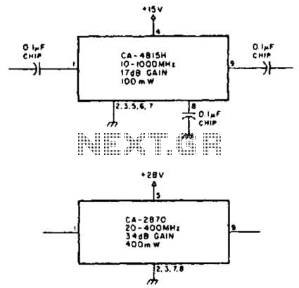
Wideband Power Amplifier Circuit
Using TRW part number CA-815H, a 17 dB gain amplifier capable of delivering 100 mW over a frequency range of 10 to 1000 MHz can be constructed. Additionally, the CA-2870 can provide 0.4 W with a gain of 34 dB...

Wideband Test Amplifier
This single-stage amplifier, utilizing a 2N2222 or 2N3904 general-purpose transistor, is designed for interfacing with test instruments. The transformer T1 is an Amidon Associates FT-23-43 core, wound with 17 turns of #26 wire for the primary and 6 turns for...

Wideband Active Rod Antenna
A J309 Siliconix FET is utilized to drive a 2N5109 in a wideband RF amplifier setup. A relay is incorporated to bypass the amplifier in transmit mode, if required. An active antenna element is a 2-meter 5/8-wave whip. The amplifier...
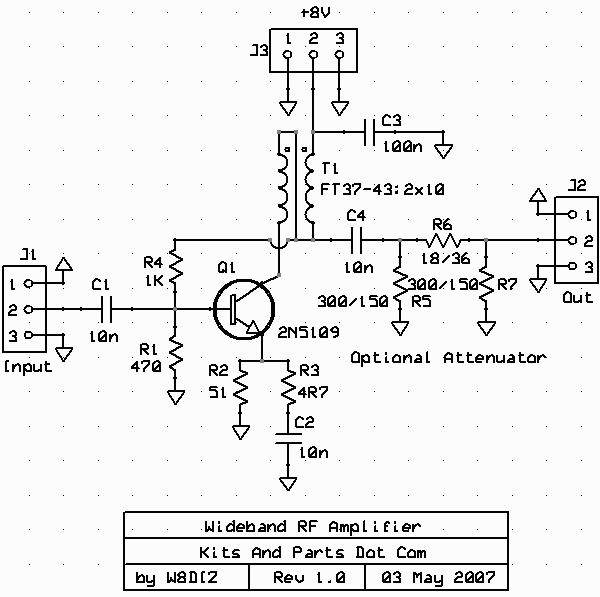
Universal Wideband Amp
This kit is part of what is referred to as RF Tool Kits, specifically Electronic Building Blocks. A variety of these kits are available, with new ones being released periodically. The offerings can be explored and built in a homebrew...

Wide Band Fuel Mixture Display
This document is an introduction to the Wideband Fuel Mixture Display (FMD). We modified the original Silicon Chip Fuel Mixture Display (that used a narrowband sensor) for use as a display for the DIY-WB wideband oxygen sensor controller. After first...

Wideband Active Small Magnetic Loop Antenna
There are extremely wideband software-defined radios (SDR) where a wideband antenna is a natural choice. Wideband small magnetic loops (WSM loops) have been used for 3-4 decades, and their effectiveness as a wideband SDR input is under evaluation. The WSM...