



PLL 1 Watt FM transmitter
This small FM transmitter includes a limiter, a microphone amplifier and a PLL digital tuning. All the parts are placed on one circuit board. The RF power is sw...

0,4 Watt FM transmitter
Power supply: 12-14 V stab., 100 mA. RF power: 400 mW. Impedance: 50-75 ohm. Frequency range: 87,5-108 MHz. Modulation: wideband FM. Connect the 6 V / 0,1 A bul...

AM To FM converter
This circuit can be used to recieve AM stations in an FM radio. Is a regenerative circuit that samples AM signals of all frequency and retransmits them in the F...

CW Transmitter
This one-valve (ECL82) CW Transmitter occupies a very special place in my amateur radio history. I was first licensed in 1994 but did not operate on air. I comm...

PC FM radio
Stabilised tendency of catering: Vcc=9~12V. Frequency of reception: 88~108MHz. Consumption: 100mA. If you know some language of programming as C ++, PASCAL, VI...

FM transmitter 2N2222
This circuit is a simple two transistor (2N2222) FM transmitter. No license is required for this transmitter according to FCC regulations regarding wireless mic...

1.57-GHz Front-End for GPS Receiver
The GPS is based on 24 satellites located in six orbital planes at a height of 20 200 km and circle the Earth every 12 h. Each plane is inclined at 55 to the Ea...

RF Recieving Amplifier for 40MHZ
The sensitivity of receiver it is possible to increase itself considerably, if is interfered, between this and his aerial, a amplifier RF. The amplifier of cir...

Two channel frequency synthesizer
This instrument is a one or two channel frequency synthesizer. DC to 35 MHz frequency with 0.1 Hz resolution. +16 to -48 dBm signal level with 0.1 dB resolutio...

FM Transmitter with PLL
In order to simplify the transmitter design, we've used the new pll circuit from Motorola :the MC145170. This PLL includes the prescaler and a serial standard b...

FM PLL transmitter
This new FM transmitter is very easy to make and doesn't need any RF tuning. First of all ,we have used an integrated VCO: The POS150 from Mini-circuits. This e...

Microphone FM bug transmitter
This is the basic fm trasmitter that I built. In theory, according to electronics, it shouldn't work but works fine and is very sensitive. It can transmit the s...

41-72MHz micro-receiver ( MC3362 )
This receiver weighs about 6 g, used in 41 and 72 MHz, met a great success with readers of the magazine. The RX22 is the subject of these lines is improved RX20...

ALL band reciever using MC3362
This receptor is born of our annoyance against the irritating problem of Quartz: With the RX21, completed research of cut crystal for your personal rating, you ...

PLL 41MHz reciever with 68HC711D3
The quartz QZ1 of the preceding receivers which set the work frequency is not on the market any more. It is replaced
by a locking phase loop allowing the free ...

HF reciever with MC3362
The diagram of detail of Fig.2 gives additional precise details: The signal HF collected by the antenna is amplified by T1, framed reel S of agreement L1 and ...

FM Stereo Transmitter with BA1404
You'll find that this is a very easy project to build. It will transmit good quality sound in the FM band ( 88 - 108 mhz ). One inportant item is that the IC ch...

FM Electrocardiogram Monitor with LM331/LM231
V_logic is connected to the power supply Vs and all ground are connected to the negative terminal of the battery. Fout is a square wave of varying frequency wit...
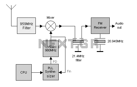
Making a 900MHz Phone Bug
Today they have moved up to 900MHz. It is not easy to build stuff for 900MHz so in this project I will re-use an old cordless 900MHz phone I found in a containe...

Automatic Frequency Control FM reciever
This is a measurement I did on a FM receiver (MC3372). I have plooted the output DC-bias as function of the IF (Intermediate Frequency) frequency. At 455kHz you...