

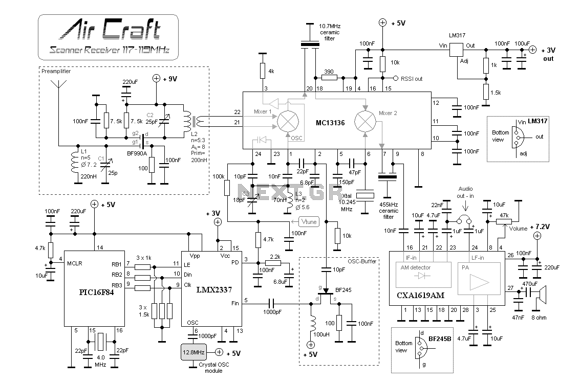

Aircraft band / AM Receiver with PIC16F84
Aircraft communication is still AM modulated and the frequency is about 110-125 MHz. What differ this construction from my two previous is that I have implemen...
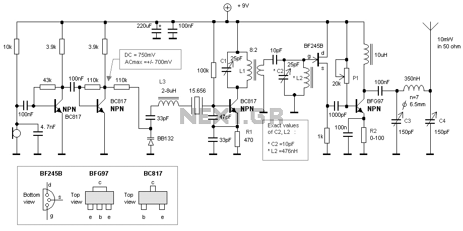
50MHz crystal bug
This bugg is based on my previous 3-transistor transmitter. This bugg unit has many advantage. The transmitter use a crystal 46.515MHz to hold a steady frequenc...
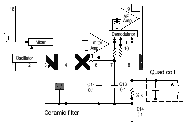
Ceramic resonator oscillator
This receiver is MC3371. Pin 16 is the RF input to the mixer and pin1 and pin2 is the local oscillator. The product comes out at pin 3. Imagin you want to recei...

DTMF FM PLL Receiver
This project is a PLL synthesized FM radio which can decode DTMF. The receiving frequency can be set by the PLL circuit from 80-140MHz. The receiver is VERY sta...
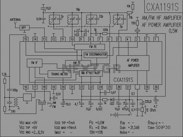
CXA1191 AM/FM Reciever
The radio IC is in the middle of the board. Above the IC you will find a ceramic filter (10.7MHz) for the FM part. This filter is blue. At the top you will find...
Simple RF field meter with LM358
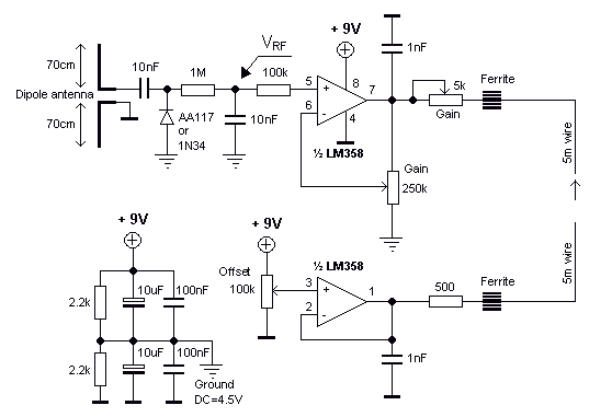
This project will explain the function of a simple RF field meter. The unit will be in great help to tune transmitters for best performances. At the bottom left...

FM PLL transmitter 88-108MHz with PIC16F870
This transmitter is PLL controlled and the frequency is very stable and can be programmed digitally. The transmitter will work from 88 to 108 MHz and the output...

FM PLL controlled VCO
The main oscillator is printed in blue and is voltage controlled.
In this construction the VCO range is 88 to 108 MHz. As you can see from the blue arrows, so...
Ipod stereo 1W FM transmitter
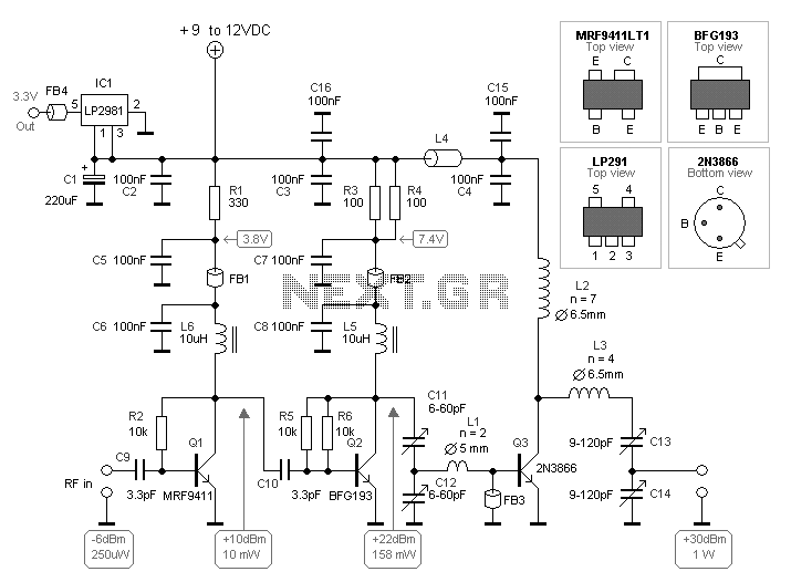
The transmitting signal can the be picked up by any FM radio receiver. Most often used in cars.
The problem with most FM transmitter is that they have very wea...
Narrow band receiver with MC13136
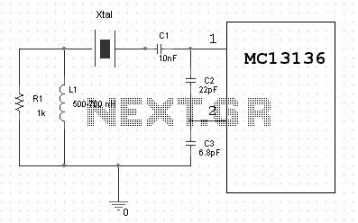
Complete Dual Conversion FM Receiver. Input frequency range 0-200MHz. Voltage byffered RSSI with 70 dbof usable range. Low voltage operation 2-6 VDC. VHF Collpi...

Scanner Reciever for 78-80 MHz with PIC16F84
This scanner use a DDS circuit to scann through the frequency band. Since I am using a DDS to set the desired frequency, this receiver can jump from one frequen...
bug transmitter with PIC16F870 PLL
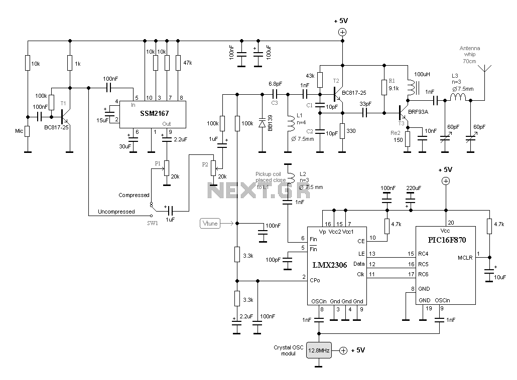
This frequency of this transmitter is PLL controlled which makes it very stable. The frequency is programmed in digitally way and can be changed very easy. Freq...
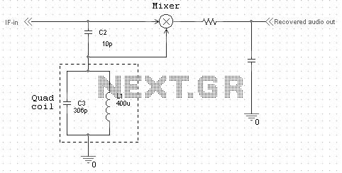
Quadrature FM Detector
Quadrature FM detectors use a high-reactance capacitor (C2) to produce two signals with a 90 degree phase difference. The phase-shifted signal is then applied t...
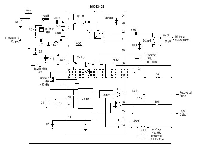
FM reciever with MC13136
One of the circuit I use in my projects is the MC13135/MC13136. It is the second generation of single chip, dual conversion FM communication receivers developed...
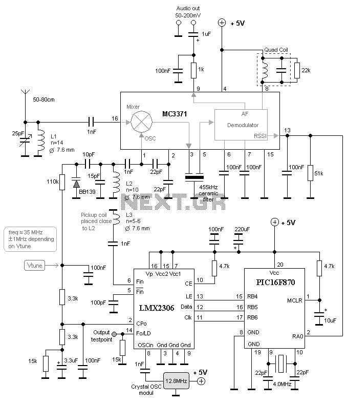
RC Receiver for model airplane
This project will explain how you can build a receiver for 35MHz. The receiver is based on the FM receiver circuit MC3371, and the frequency is PLL controlled w...

50 MHz Receiver
The purpose of this project is to build a simple receiver for 50MHz. The Receiver is built around the circuit MC3372, wich is a narrow band FM receiver. The rec...

TV-tuner receiver
The MC13136 circuit is not easy to find so I have replaced it with a new receiver circuit called SA615.
This is a basic FM receiver with very good performance ...

FM phone BUG with SA615
Many Cordless phones are still analogue and use the frequency from 30-50MHz. The signal is FM-modulated and can easy be picked up with any FM-receiver. I will p...
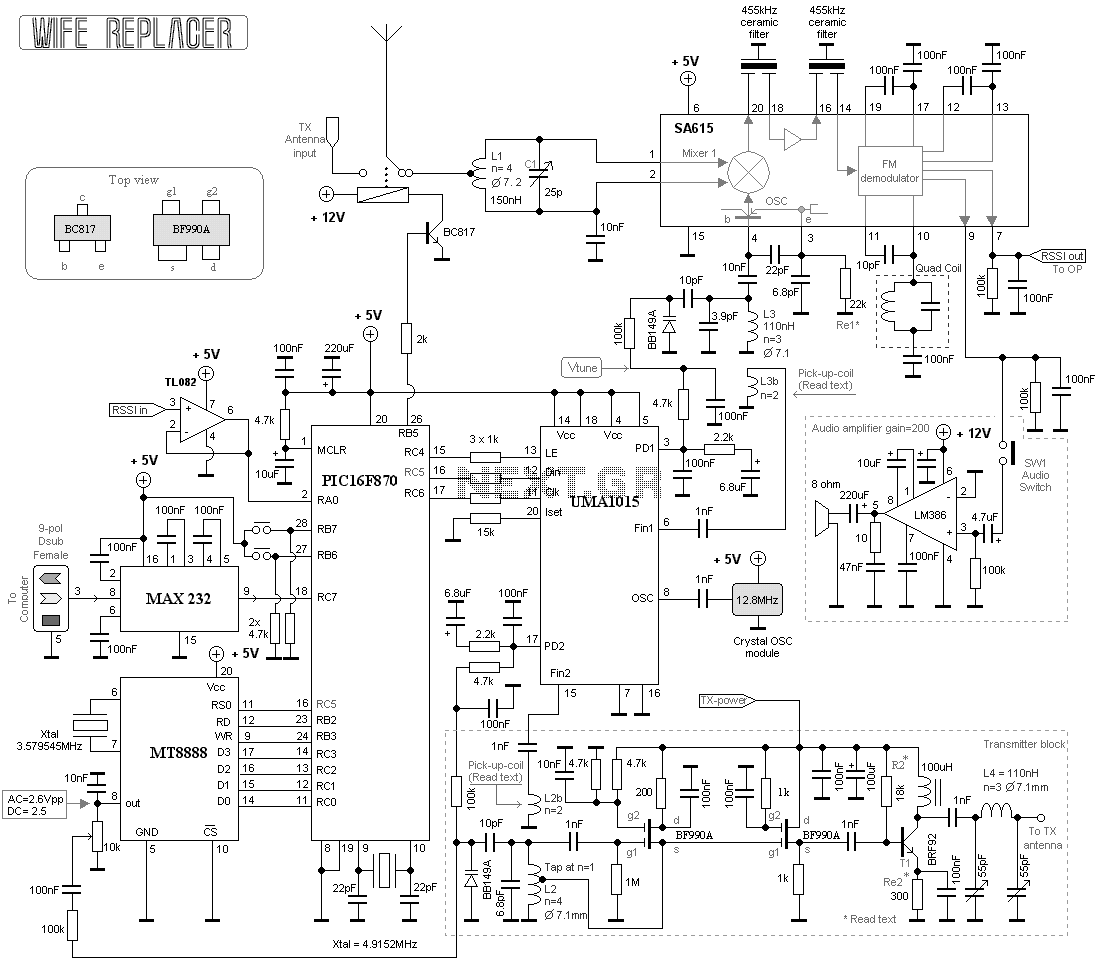
Remote tuning transmitter
This project consists of a wide range receiver and one transmitter. Together they will form a unit which will help you tuning your homebrewed transmitter. The m...

RF Digital Wattmeter
The power is measured by the circuit AD8307 over a 50 ohm dummy load. An A/D converter of 12 bit convert the analog output from the AD8307 to a digital number. ...