



AM RF Amp for Internal Antennas
The author described assembling this circuit on a 1"*1" perf board, I actually laid out a small PC board with excellent results. In this era of surface mount co...
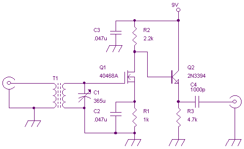
An AM RF Amp for External Antennas
I have no idea whether the RCA 40468A FET is still available or not. It came in a 4 pin metal can - with the 4th pin connected to the substrate. I have successf...

1 Watt 2.3 GHz RF Amplifier Using a MRF2001
This is an image Schematic. No Description available....

SSB ADAPTOR
Most experienced amateurs know that SSB (single side band) reception requires a receiver fitted with a product detector or BFO (beat frequency oscillator) to re...

SW Receiver Using MK414
The tuned circuit consists of a variable capacitor and fixed air spaced coil. For the coil, I wound between 10 and 20 turns of wire on an empty tube of around 1...

Superregenerative receiver
This is a simple RF receiver mainly for low-distance digital radio receiver application. The analog output of this circuit should be connected to a schmitt-trig...

VLF Radio Receiver circuit
This version sports a 2nd audio amplifier stage at Q3. The output level with this version is sufficient to drive a crystal headphone to a comfortable volume. Th...
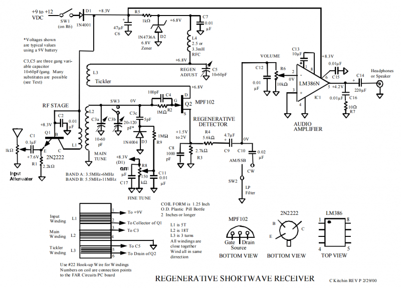
REGENERATIVE SHORTWAVE RECEIVER
Use #22 Hook-up Wire forWindings. Numbers on coil are connection points to the FAR Circuits PC board....

RECEIVER BUILDING BLOCKS
This amplifier has about 20dB of gain, bandwidth of 100MHz and noise figure of about 7dB. The output transformer is 8 turns bifilar wound on a ferrite core. Use...

FM Receiver
An FM regenereative receiver using a single FET and one audio amplifier IC....

Complete Radio Set with MK484 and Loudspeaker
A complete AM radio set based on the MK484 IC (formerly ZN414). It uses a PNP transistor and can drive a 150R loudspeaker. Chad has built a complete radio recei...

Mini FM Receiver using TDA7088
The electronic diagram of the monophonic FM receiver made with TDA7088T is shown on Pic.4.12. If built with SMD components it can be placed in a matchbox, altog...

A high-performance FM receiver for audio and digital applicatons
A block diagram and a schematic of the receiver are shown in Figures 2 and 3, respectively. In Figure 3, L6 and L7 are spaced 0.6 inch for a loss of about 0.5 d...

Hear Amateurs on your FM Radio!
If you`re the sort who`d like to have an HF receiver in every room, but can`t afford it, this idea is for you. It will also appeal to the beginner wishing to bu...

Baseband Circuits for an RFID Receiver
Figure 1 shows the block diagram of a direct conversion RF receiver—the receiver demodulates an RF carrier directly into a baseband signal without an intermed...
AM RADIO RECEIVERS
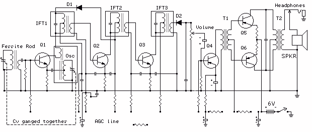
Firstly because of the modulation process we generate at least two copies of the intelligence plus the carrier. For example consider a local radio station trans...

A SHORT WAVE REGENERATIVE RECEIVER PROJECT
A regenerative radio receiver is unsurpassed in comparable simplicity, weak signal reception, inherent noise-limiting and agc action and, freedom from overloadi...
CRYSTAL RADIO SET
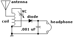
Here is the schematic diagram for a very basic crystal radio set without any particular embellishments. This basic old time radio uses no power other than that ...

Add a signal-strength display to an FM-receiver IC
The IC has an FLL (frequency-locked-loop) structure. The filtered output of the FM discriminator frequency-modulates the local oscillator to provide negative-fe...
45-860MHz Radio receiver based on UV916-tuner
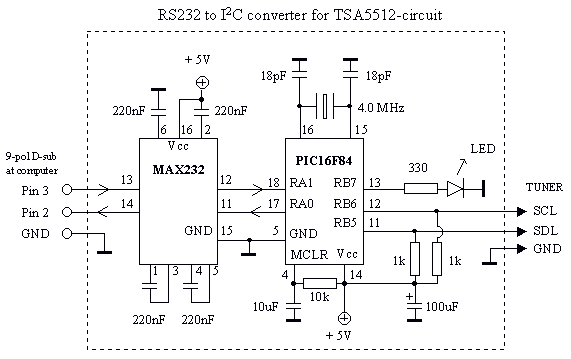
To build a Spectrum analyzer I needed a tuner. I also needed to learn how to control the tuner. In some old broken TV I found the tuner UV916. It is a common us...