



A 30 Mtr Direct Conversion Receiver for QRSS
The schematic for the crystal bandpass filter/amplifier board appears below (left) withimages of the assembled and boxed unit appearing below center andright. T...

Aligning the Henry Radio 30A02 (Tempo S-30) RF Amplifier
...

Battery Powered Tube Regenerative Receiver
Basic Regen design is pretty common, so BEFORE the schematic comes the "concept stage", the "what`s available in the junkbox stage", back to the "concept stage"...

ZL1BPU exciter
Direct Digital Synthesis (DDS) frequency generation has been around for quite a while, but most of the homebrew DDS projects are rather complex and use expensiv...

A Journey into Building Radio Transmitters with Vacuum Tubes
A copy from an old italian magazine of amatorial electronics, proposing an add-on for tube receivers. The add-on was a simple one-tube short-wave transmitter le...

200W 136 kHz transmitter
Output transformer core: coming from flea market, light blue color, marked as A-438281-2-9H9-3, OD = 47 mm, ID = 24 mm, height = 13 mm. No information about µ ...
136 kHz QRSS receiver
For digital modes the ideal receiver must be very simple, front end selectivity, manually adjustable gain, IF filter. All the goodies you can find on the HF rec...

Old Ham Radio Stuff
...

Using Spectrum Lab for reception of natural radio
...

AB4YD Amateur Radio Page
This project was inspired by a series of QST articles by Hayward, W1PH. I based my rig on his April 1962 article, "Have You Tried 160 Lately ". I liked his simp...

1929 MOPA 80 meter transmitter using a pair of 27 triodes to an 865 tetrode
This transmitter had its origins as a conventional shunt fed Hartley oscillator for 80 meters using a pair of 27 triodes connected in parallel; with 300 VDC on ...

Callsign
I still prefer the low HF bands and mostly operate CW, with some PSK31 and SSB. Transceivers include an Elecraft K3 + SDR-IQ as a panadapter, and Flex 6700. Amp...

40 m Band Superhet Receiver
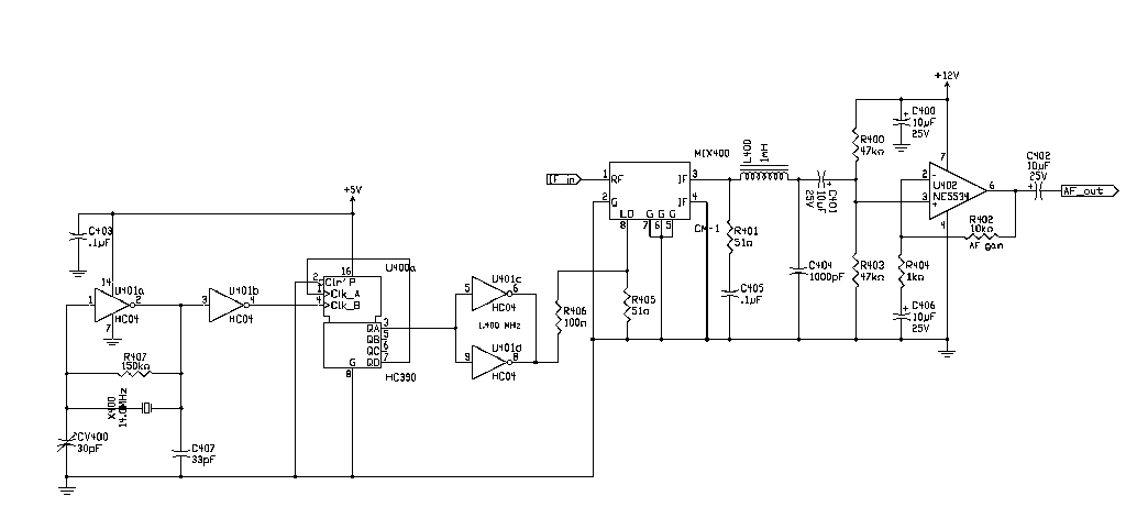
By the addition of one integrated circuit and some passive components, I was able to convert my earlier developed 40-meter direct conversion receiver design int...
RF-Workbench
...

Simple Direct Conversion Receiver
Low-cost CW superhet receiver with a 4. 00 MHz Intermediate frequency. There is no AGC or RF gain control, however this receiver has good large signal handling ...

Simple Direct Conversion Receiver
...

Misc RF Topics
The LO system from the project entitled A Monoband SSB/CW Transceiver in Chapter 6 of EMRFD. The mega low (about -20 dBm) output from a diode ring mixing a VFO ...

Hobby and Fun
Above ” 2 air variable capacitors and a copper clad board screwed onto a piece of wood for my bench musing. Regenerative receivers delight and amaze ” some ...

VHF-FM-supplement.asp
...

VFO circut
Building VFOs in 2011 might seem an irrelevant exercise given the move to and evolution of digital signal generators laden with bells and whistles like memories...