


Infra-Red Remote Control Tester
#infra-red
#IR tester
#remote control tester
#Schmitt trigger
#battery-powered
#compact
#quick test
#go/no-go
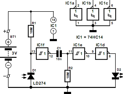
Description: This circuit is essential for quickly determining the functionality of various remote control transmitting infrared (IR) lights. It is powered by a battery and constructed from a few commonly available and inexpensive components, fitting into a compact enclosure. The Schmitt trigger gate IC1f functions as a quasi-analog amplifier, utilizing an infrared emitting diode (IRED) type LD274 as the sensor element. An R-C network, consisting of capacitor C1 and resistor R2, is implemented at the output of the gate to prevent the output LED, D2, from lighting constantly in the presence of continuous IR sources, such as daylight. This creates an effective testing option: when the tester is pointed at direct daylight, the indicator LED should briefly illuminate. The tester is sensitive enough to detect IR light from remote controls at distances up to 50 cm. The circuit is designed for very low power consumption, drawing less than 1 mA from the battery when IR light is detected, and nearly no current when IR light is absent, eliminating the need for an on/off switch. The construction drawing illustrates how the tester can be housed in a small ABS case sourced from Conrad.
This infrared light tester circuit is a practical tool for evaluating the performance of remote control devices. The core component, the Schmitt trigger gate IC1f, is configured to amplify the weak signals received from the IRED, which serves as the sensor capable of detecting IR light. The choice of the LD274 diode is crucial, as it is sensitive to the specific wavelengths emitted by typical remote controls.
The R-C network, formed by capacitor C1 and resistor R2, plays a vital role in shaping the output signal. It ensures that the output LED, D2, does not remain continuously illuminated when exposed to steady IR sources, such as sunlight or artificial lighting. Instead, the circuit is designed to respond to pulse bursts, which are characteristic of remote control signals. This design allows for a clear indication of whether a remote control is functioning correctly, as the LED will light up momentarily in response to valid IR signals.
The sensitivity of the circuit is optimized to detect IR signals from distances of up to 50 cm, making it suitable for general testing applications. The low power consumption of the circuit, drawing less than 1 mA during operation and virtually no current in the absence of IR light, enhances its usability. This efficiency means that the tester can remain in a ready state without the need for manual power management, such as an on/off switch.
The compact design of the circuit allows it to be enclosed in a small ABS case, which provides protection and portability. The construction drawing serves as a guide for assembling the components securely within the enclosure, ensuring ease of use and accessibility for anyone needing to test remote control devices. Overall, this circuit is a valuable addition to the toolkit of anyone working with infrared remote controls, providing a quick and reliable method for performance verification.This little circuit is invaluable for quick go/no-go testing of just about any remote control transmitting infra-red (IR) light. The tester is battery-powered, built from just a handful of commonly available and inexpensive parts, and fits in a compact enclosure.
Schmitt trigger gate IC1f is used as a quasi-analogue amplifier with, unusually, an i nfra-red emitting diode (IRED) type LD274 acting as the sensor element. An R-C network, C1-R2, is used at the output of the gate because all IR remote controls transmit pulse bursts, and to prevent the output LED, D2, lighting constantly when day-light or another continuous source of IR light is detected. This creates a useful quick test` option: point the tester at direct daylight, and the indicator LED should light briefly.
The sensitivity of the tester is such that IR light from remote control is detected at a distance of up to 50 cm. The circuit is designed for very low power consumption, drawing less than 1 mA from the battery when IR light is detected, and practically no current when no light is detected.
Hence no on/off switch is required. The construction drawing shows how the tester may be cased` using a small ABS case from Conrad.
This infrared light tester circuit is a practical tool for evaluating the performance of remote control devices. The core component, the Schmitt trigger gate IC1f, is configured to amplify the weak signals received from the IRED, which serves as the sensor capable of detecting IR light. The choice of the LD274 diode is crucial, as it is sensitive to the specific wavelengths emitted by typical remote controls.
The R-C network, formed by capacitor C1 and resistor R2, plays a vital role in shaping the output signal. It ensures that the output LED, D2, does not remain continuously illuminated when exposed to steady IR sources, such as sunlight or artificial lighting. Instead, the circuit is designed to respond to pulse bursts, which are characteristic of remote control signals. This design allows for a clear indication of whether a remote control is functioning correctly, as the LED will light up momentarily in response to valid IR signals.
The sensitivity of the circuit is optimized to detect IR signals from distances of up to 50 cm, making it suitable for general testing applications. The low power consumption of the circuit, drawing less than 1 mA during operation and virtually no current in the absence of IR light, enhances its usability. This efficiency means that the tester can remain in a ready state without the need for manual power management, such as an on/off switch.
The compact design of the circuit allows it to be enclosed in a small ABS case, which provides protection and portability. The construction drawing serves as a guide for assembling the components securely within the enclosure, ensuring ease of use and accessibility for anyone needing to test remote control devices. Overall, this circuit is a valuable addition to the toolkit of anyone working with infrared remote controls, providing a quick and reliable method for performance verification.This little circuit is invaluable for quick go/no-go testing of just about any remote control transmitting infra-red (IR) light. The tester is battery-powered, built from just a handful of commonly available and inexpensive parts, and fits in a compact enclosure.
Schmitt trigger gate IC1f is used as a quasi-analogue amplifier with, unusually, an i nfra-red emitting diode (IRED) type LD274 acting as the sensor element. An R-C network, C1-R2, is used at the output of the gate because all IR remote controls transmit pulse bursts, and to prevent the output LED, D2, lighting constantly when day-light or another continuous source of IR light is detected. This creates a useful quick test` option: point the tester at direct daylight, and the indicator LED should light briefly.
The sensitivity of the tester is such that IR light from remote control is detected at a distance of up to 50 cm. The circuit is designed for very low power consumption, drawing less than 1 mA from the battery when IR light is detected, and practically no current when no light is detected.
Hence no on/off switch is required. The construction drawing shows how the tester may be cased` using a small ABS case from Conrad.

Multi-way pocket alarm circuit
This circuit is a two-way alarm system that utilizes a Schmitt IC, featuring responsive sound and light indicators. It is compact, energy-efficient, and consists of only 13 components, making it a cost-effective solution. The circuit is divided into two sections...

74HC11 Infra-Red Remote Control Tester
This circuit is an Infra-Red Remote Control Tester designed to verify the functionality of any remote control that transmits infrared (IR) light. It operates on a 3V battery and offers several advantages, such as its compact size and the use...

Battery Powered Night Lamp circuit
This circuit functions as a night lamp when a wall mains socket is unavailable for plugging in a continuously operating small neon lamp device. To minimize battery consumption, it utilizes a single 1.5V cell, and a simple voltage doubler drives...

40khz IR tester
Use this circuit to test if the light coming from your 40kHz IR emitter is really emitting the right frequency. The schematic says to use a GP1U5X IR module, but probably any 40kHz detector module will work. I used a...

Schmitt Trigger VU Meter
The schematic indicates that the input is routed through a voltage divider. This configuration is essential for the operation of the Schmitt triggers, which all activate under certain conditions.
The voltage divider in the schematic serves to scale down the input...

Schmitt trigger zero crossing detector
This circuit features a 100 mV hysteresis, suitable for applications demanding rapid output transition times despite slow input signals. The hysteresis loop minimizes false triggering caused by noise on the input. The accompanying waveforms illustrate the trip points established by...
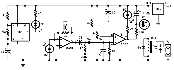
Infra-red Level Detector
This circuit is useful in liquids level or proximity detection. It operates detecting the distance from the target by reflection of an infra-red beam. It can safely detect the level of a liquid in a tank without any contact with...

Schmitt Inverter
The Schmitt trigger is a specialized circuit that functions as a switch, altering its state at two distinct voltage thresholds known as the upper and lower thresholds, or the positive and negative-going thresholds. The difference between these two threshold levels...

Schmitt trigger with LM741 op-amp
The schmitt trigger circuit is built around a single LM741 op-amp, its output buffered by a transistor, which in turn energizes a relay. The relay may be replaced by a red LED if desired. The LM741 may be replaced by...