


Xenon-flash-trigger
#xenon flash
#photographic flash
#remote trigger
#slave flash
#light sensor
#wireless trigger
#camera accessory
#flash synchronization
#photography

Description: This circuit is utilized for remote photographic flash units that synchronize with the flash attached to the camera. It is designed to connect to the trigger cord or hot shoe of a commercial portable flash unit, allowing the unit to be triggered by the light emitted from the camera's flash. This setup enables remote operation without requiring wires or cables between the various components. To prevent an inadvertent flash upon connection, the flash trigger unit should be connected to the slave flash before powering on the flash.
The L14C1 phototransistor features a wide, nearly cosine viewing angle, making alignment non-critical. For applications requiring a more sensitive and directional remote trigger, the circuit can be adapted by using an L14G2 lensed phototransistor as the sensor. This lensed transistor offers a viewing angle of approximately 10 degrees, resulting in over a tenfold increase in light sensitivity (with a threefold range improvement). It is important to note that the phototransistor is configured in a self-biasing circuit that is relatively unaffected by slow-changing ambient light, while still discharging the 0.01 µF capacitor into the gate of the C106D upon exposure to a photo flash. For a more compact design, the C106D can be substituted with a C205D, provided that the duty cycle is appropriately reduced.
The circuit operates by utilizing the phototransistor to detect the flash from the primary camera-mounted unit. When the camera's flash is triggered, the light from this flash illuminates the phototransistor, which then activates the connected slave flash unit. The self-biasing nature of the circuit ensures that it remains stable in varying light conditions, making it an effective solution for photographers seeking to achieve synchronized lighting without the clutter of physical connections. The choice of phototransistor can significantly influence the performance and sensitivity of the setup, allowing for customization based on specific photographic needs.
In summary, this circuit provides a reliable and flexible means of achieving remote flash synchronization, enhancing the versatility of photographic lighting setups. The ability to modify components for sensitivity and size further contributes to its utility in various photographic scenarios.This circuit is used for remote photographic flash units that flash at the~ame time as the flash attached to the camera. This circuit is designed to the trigger cord or hot shoe connection of a commercial portable flash unit and triggers the unit from the light produced by the light of the flash unit attached to the camera.
This provides remoteoperation without the need for wires or cables between the various units. The flash trigger unit should be connected to the slave flash before turning the flash on to prevent a d VIdt triggered flash on connection. The L14C1 phototransistor has a wide, almost cosine viewing angle, so aligmnent is not critical. If a very sensitive, more directional remote trigger unit is desired, the circuit can be modified using an L14G2 lensed phototransistor as the sensor. The lens on this transistor provides a viewing angle of approximately 10° and gives over a 10 to 1 improvement in light sensitivity (3 to 1 range improvement).
Note that the phototransistor is connected in a self-biasing circuit which is relatively insensitive to slow-changing ambient light, and yet discharges the 0.01-I"F capacitor into the Cl06D gate when illuminated by a photo flash. For a physically smaller size, the C106D can be replaced by a C205D, if the duty cycle is reduced appropriately.
The L14C1 phototransistor features a wide, nearly cosine viewing angle, making alignment non-critical. For applications requiring a more sensitive and directional remote trigger, the circuit can be adapted by using an L14G2 lensed phototransistor as the sensor. This lensed transistor offers a viewing angle of approximately 10 degrees, resulting in over a tenfold increase in light sensitivity (with a threefold range improvement). It is important to note that the phototransistor is configured in a self-biasing circuit that is relatively unaffected by slow-changing ambient light, while still discharging the 0.01 µF capacitor into the gate of the C106D upon exposure to a photo flash. For a more compact design, the C106D can be substituted with a C205D, provided that the duty cycle is appropriately reduced.
The circuit operates by utilizing the phototransistor to detect the flash from the primary camera-mounted unit. When the camera's flash is triggered, the light from this flash illuminates the phototransistor, which then activates the connected slave flash unit. The self-biasing nature of the circuit ensures that it remains stable in varying light conditions, making it an effective solution for photographers seeking to achieve synchronized lighting without the clutter of physical connections. The choice of phototransistor can significantly influence the performance and sensitivity of the setup, allowing for customization based on specific photographic needs.
In summary, this circuit provides a reliable and flexible means of achieving remote flash synchronization, enhancing the versatility of photographic lighting setups. The ability to modify components for sensitivity and size further contributes to its utility in various photographic scenarios.This circuit is used for remote photographic flash units that flash at the~ame time as the flash attached to the camera. This circuit is designed to the trigger cord or hot shoe connection of a commercial portable flash unit and triggers the unit from the light produced by the light of the flash unit attached to the camera.
This provides remoteoperation without the need for wires or cables between the various units. The flash trigger unit should be connected to the slave flash before turning the flash on to prevent a d VIdt triggered flash on connection. The L14C1 phototransistor has a wide, almost cosine viewing angle, so aligmnent is not critical. If a very sensitive, more directional remote trigger unit is desired, the circuit can be modified using an L14G2 lensed phototransistor as the sensor. The lens on this transistor provides a viewing angle of approximately 10° and gives over a 10 to 1 improvement in light sensitivity (3 to 1 range improvement).
Note that the phototransistor is connected in a self-biasing circuit which is relatively insensitive to slow-changing ambient light, and yet discharges the 0.01-I"F capacitor into the Cl06D gate when illuminated by a photo flash. For a physically smaller size, the C106D can be replaced by a C205D, if the duty cycle is reduced appropriately.

Light Sensor including Photocell and LDR Sensor
Electronics tutorial about light sensors including photocells, LDR, photodiodes, phototransistors, photovoltaic cells, and light-dependent resistors.
Light sensors are crucial components in various electronic applications, enabling devices to respond to changes in ambient light levels. This tutorial covers several types of light...
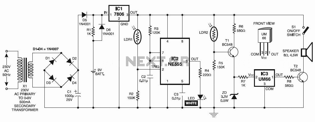
Automatic Night Lamp with Morning Alarm
This circuit automatically activates a night lamp when the bedroom light is turned off. The lamp stays illuminated until the light sensor detects daylight in the morning. A super-bright white LED is utilized as the night lamp, providing bright and...

Light Controlled Relays
The first circuit energizes the relay when the light rises above the preset level. The second circuit energizes the relay when the light falls below the preset level. The two circuits are practically identical. The only difference between them is...
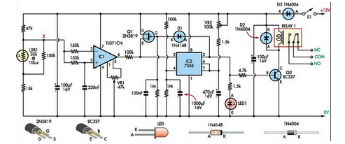
Super Light Sensor
This Super Light Sensor responds to minute fluctuations in light levels, automatically adjusting from approximately 200 lux to 60,000 lux (from a modestly lit room to direct sunlight). It has various potential applications, such as detecting a car entering a...
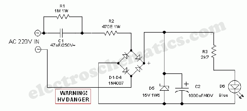
Automatic Night Lamp with Morning Alarm
This circuit project automatically activates a night lamp when the bedroom light is turned off. The lamp stays illuminated until the light sensor detects daylight.
The circuit operates using a light-dependent resistor (LDR) as the primary sensor to detect ambient light...
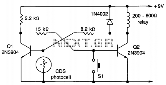
Light-operated switch
This circuit employs a flip-flop configuration utilizing Q1 and Q2. Under normal conditions, Q1 is heavily conducting. When light is detected by the CDS photocell, the bias on Q1 decreases, resulting in its cutoff, which activates Q2 and removes the...

light sensor circuit using pic16c63
This light sensor circuit, utilizing a photosensor, serves as a bridge between light and electronics. It is constructed using an operational amplifier and the PIC16C63 microcontroller to control the sensor. While the circuit is not intended for precision applications, it...

Arduino Light Sensors
A project is underway to determine the number of sun hours available at a specific location and to track this data over time as part of solar power installation design. The concept involves utilizing a light detector exposed to sunlight...

home-made light-operated camera trigger
This device is designed to capture images of moving objects by activating a camera or flashgun when one or two light beams are interrupted. Originally intended for photographing insects in flight, it can also be utilized for projectiles and other...