


Servoelectric Guitar Project
#servomotor
#USB interface
#guitar
#digital outputs
#analog outputs
#Velleman K8055
#computer control
#music

Description: The current Milwaukee Guitar design utilizes an off-board computer (a desktop PC) to control the servomotors. A standard USB number pad is connected to the computer, which provides output signals through a Velleman K8055 USB experiment interface board to the servo circuits. This K8055 board features eight digital outputs and two analog outputs. To obtain three analog voltages, a sample and hold circuit was constructed using a CMOS CD4066 quad bilateral switch and two LF353 high input impedance operational amplifiers. The K8055 was controlled with a program written in Borland C, which runs in the command window on a Microsoft Windows operating system. This program allows for the tuning of the guitar one string at a time and provides an arbitrary mapping of keyboard keys to combinations of string tensions.
The Milwaukee Guitar system employs a sophisticated architecture that integrates digital control with analog signal processing to achieve precise tuning of the instrument. The core of the system is a desktop PC that acts as the central processing unit, interfacing with a USB number pad for user input. This setup allows musicians to input commands easily, which are then translated into control signals for the servomotors responsible for adjusting the tension of the guitar strings.
The Velleman K8055 USB experiment interface board serves as a crucial link between the computer and the servo circuits. This board's eight digital outputs are utilized to send binary signals to the servomotors, enabling them to move to specific positions based on the desired string tension. The two analog outputs are critical for generating the necessary control voltages for the sample and hold circuit.
The design of the sample and hold circuit is key to producing the three distinct analog voltages required for tuning. The CMOS CD4066 quad bilateral switch allows for the routing of signals with minimal distortion, ensuring that the integrity of the control voltages is maintained. The LF353 operational amplifiers, known for their high input impedance, provide the necessary buffering and amplification, ensuring that the signals are robust enough to drive the servomotors effectively.
The software component, developed in Borland C, allows for real-time control and tuning of the guitar. The program's design accommodates the tuning of individual strings, providing musicians with the flexibility to customize their tuning preferences. The arbitrary mapping of keyboard keys to specific string tensions enables a user-friendly interface, allowing for intuitive control over the tuning process.
Overall, the Milwaukee Guitar system represents an innovative fusion of digital electronics and traditional musical instruments, leveraging advanced technology to enhance the musician's experience.The current Milwaukee Guitar design uses an off-board computer (a desktop PC) to control the servomotors. A standard USB number pad is connected to the computer which then provides output signals through a Velleman K8055 USB experiment interface board to the servo circuits.
This K8055 board provides eight digital outputs and two analog outputs. In order to get three analog voltages, a sample and hold circuit using a CMOS CD4066 quad bilateral switch and two LF 353 high input impedance operational amplifiers was constructed. (schematic) The KE 8055 was controlled with C program written in Borland C (available free from Borland ) executing in the command window on a Microsoft Windows operating system.
The program permits tuning of the guitar one string at a time and provides an arbitrary mapping of keys of the keyboard to combinations of string tensions.
The Milwaukee Guitar system employs a sophisticated architecture that integrates digital control with analog signal processing to achieve precise tuning of the instrument. The core of the system is a desktop PC that acts as the central processing unit, interfacing with a USB number pad for user input. This setup allows musicians to input commands easily, which are then translated into control signals for the servomotors responsible for adjusting the tension of the guitar strings.
The Velleman K8055 USB experiment interface board serves as a crucial link between the computer and the servo circuits. This board's eight digital outputs are utilized to send binary signals to the servomotors, enabling them to move to specific positions based on the desired string tension. The two analog outputs are critical for generating the necessary control voltages for the sample and hold circuit.
The design of the sample and hold circuit is key to producing the three distinct analog voltages required for tuning. The CMOS CD4066 quad bilateral switch allows for the routing of signals with minimal distortion, ensuring that the integrity of the control voltages is maintained. The LF353 operational amplifiers, known for their high input impedance, provide the necessary buffering and amplification, ensuring that the signals are robust enough to drive the servomotors effectively.
The software component, developed in Borland C, allows for real-time control and tuning of the guitar. The program's design accommodates the tuning of individual strings, providing musicians with the flexibility to customize their tuning preferences. The arbitrary mapping of keyboard keys to specific string tensions enables a user-friendly interface, allowing for intuitive control over the tuning process.
Overall, the Milwaukee Guitar system represents an innovative fusion of digital electronics and traditional musical instruments, leveraging advanced technology to enhance the musician's experience.The current Milwaukee Guitar design uses an off-board computer (a desktop PC) to control the servomotors. A standard USB number pad is connected to the computer which then provides output signals through a Velleman K8055 USB experiment interface board to the servo circuits.
This K8055 board provides eight digital outputs and two analog outputs. In order to get three analog voltages, a sample and hold circuit using a CMOS CD4066 quad bilateral switch and two LF 353 high input impedance operational amplifiers was constructed. (schematic) The KE 8055 was controlled with C program written in Borland C (available free from Borland ) executing in the command window on a Microsoft Windows operating system.
The program permits tuning of the guitar one string at a time and provides an arbitrary mapping of keys of the keyboard to combinations of string tensions.

Super Buffer for Guitars
There are instances where long cable runs from the pedalboard to the amplifier are necessary, or a more robust driving circuit is required to handle the heavy load presented by parallel devices. A suitable solution is a buffer box. The...

Guitar Reverb Pedal project
This circuit was inspired by a friend who wanted a reverb for his portable guitar amplifier. I originally tried using NE5532 low noise op-amps for the buffer stages but they were too noisy for the low level circuits so I...

Pro Maniac Guitar tube power amplifier II
This schematic is an improved version of the Pro Maniac Guitar tube power amplifier.
The improved version of the Pro Maniac Guitar tube power amplifier features several enhancements aimed at increasing performance, reliability, and sound quality. The schematic typically includes a...

69 SFPR Schematic Telecaster Guitar
A 1969 Princeton Reverb amplifier is identified as utilizing the AA764 circuit design. Various online resources provide schematics for Fender amplifiers.
The Princeton Reverb amplifier, particularly the model from 1969, is renowned for its warm tone and versatile sound characteristics, making...
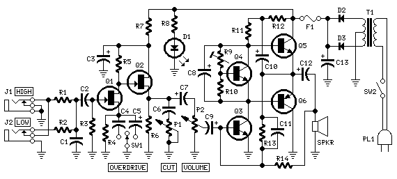
Guitar Amplifier
The aim of this design was to reproduce a Combo amplifier of the type very common in the sixties and the seventies of the past century. It is well suited as a guitar amplifier but it will do a good...
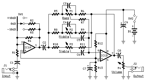
Guitar Tone Control
This preamplifier was designed as a stand-alone portable unit, useful to control the signals generated by guitar pick-ups, particularly the contact "bug" types applied to acoustic instruments. Obviously it can be used with any type of instrument and pick-up. It...

Interesting Wiring Schematic
The pickups are connected to individual volume controls that feature push/pull functionality for coil tapping. They are routed to a 5-way switch before reaching the output jack. Additionally, a switch is desired to control the bridge pickup's activation when the...

Guitars Modulator
Even with the controls set to their maximum position, there will always be some signal leakage, resulting in a loss of tone. With Module 3, engaging the bypass switch to 'Solo' disconnects the tone and volume controls from the circuit,...

Controlling The Real World With Computers
The hardware is a tinned, masked PC-based ISA data acquisition and control board that accepts up to 8 analog inputs through its 8 channel, 8-bit analog to digital converter (one has a mike preamp) produces analog output through 2 8-bit...