


Application circuit biaxial magnetic field sensor
#magnetic field sensor
#HMC1002
#AMP04
#biaxial sensor
#measurement circuit
#sensor application
#magnetic measurement
#analog circuit

Description: A biaxial magnetic field sensor application circuit is illustrated in the figure. This circuit utilizes a biaxial magnetic sensor HMC1002 along with two AMP04 operational amplifiers (A1, A2) to measure the magnetic field in both the X-axis and Y-axis directions simultaneously. The HMC1002 outputs two voltage signals that are amplified by A1 and A2, respectively. These signals are then fed into a 12-bit A/D converter, TLC2543, which includes an analog input and a reference terminal. The circuit is powered by a highly efficient DC/DC converter, MAX662A, which steps up the supply voltage from +5V to +10V, providing the necessary drive power for the IRF7105. The pulse current driver receives input signals from the interface circuit P, and the output is sent to the HMC1002 S/R+ terminal (pin 16). Tantalum capacitors, as indicated in Figure C3, are recommended for use in this circuit.
The described circuit employs the HMC1002 biaxial magnetic sensor to capture magnetic field data in two orthogonal axes, facilitating comprehensive magnetic field analysis. The sensor outputs analog voltage signals that correspond to the magnetic field strength along the X and Y axes. These signals are amplified by two operational amplifiers, AMP04, which are configured to enhance the signal levels suitable for further processing.
The amplified signals are then routed to the TLC2543, a 12-bit analog-to-digital converter (ADC). This ADC converts the analog signals into digital format, allowing for precise measurement and further digital processing. The reference terminal of the TLC2543 ensures that the conversion maintains accuracy and stability, which is crucial for applications requiring high precision.
Powering the circuit is achieved through the MAX662A DC/DC converter, which efficiently steps up the input voltage to the necessary levels. This converter is essential for providing the required voltage to the IRF7105, a power MOSFET used in the circuit. The IRF7105 serves as a pulse current driver, enabling the circuit to handle the necessary output current for driving loads or interfacing with other components.
The input signals for the pulse current driver are sourced from the interface circuit P, ensuring that the system can be integrated seamlessly with other electronic components or systems. The output from the driver is directed to the S/R+ terminal of the HMC1002, allowing for effective communication and control of the sensor's operation.
The inclusion of tantalum capacitors, as specified in Figure C3, is important for maintaining stability and filtering within the circuit. These capacitors are known for their reliability and performance in various electronic applications, making them suitable for this high-performance magnetic sensing circuit. Overall, this circuit design exemplifies a robust approach to measuring and processing magnetic fields in two dimensions, suitable for various applications in fields such as robotics, navigation, and industrial automation. Biaxial magnetic field sensor application circuit as shown in FIG. Using a biaxial magnetic sensor HMC1002, two AMP04 (A1, A2), the magnetic field can simultaneously measure th e X-axis direction and the Y-axis direction. HMC1002 two voltage signals outputted respectively after A1 and A2 amplification, then the analog input and the reference terminal 12 bit A/D converter TLC2543, and then connected via the interface circuit P. MAX662A is a highly efficient DC/DC converter can be raised to + 5V power supply + 10V, as the drive power IRF7105.
Pulse current driver input signal from the P, the output is sent to the HMC1002 S/R + terminal (pin 16). Figure C3 tantalum capacitors should be used.
The described circuit employs the HMC1002 biaxial magnetic sensor to capture magnetic field data in two orthogonal axes, facilitating comprehensive magnetic field analysis. The sensor outputs analog voltage signals that correspond to the magnetic field strength along the X and Y axes. These signals are amplified by two operational amplifiers, AMP04, which are configured to enhance the signal levels suitable for further processing.
The amplified signals are then routed to the TLC2543, a 12-bit analog-to-digital converter (ADC). This ADC converts the analog signals into digital format, allowing for precise measurement and further digital processing. The reference terminal of the TLC2543 ensures that the conversion maintains accuracy and stability, which is crucial for applications requiring high precision.
Powering the circuit is achieved through the MAX662A DC/DC converter, which efficiently steps up the input voltage to the necessary levels. This converter is essential for providing the required voltage to the IRF7105, a power MOSFET used in the circuit. The IRF7105 serves as a pulse current driver, enabling the circuit to handle the necessary output current for driving loads or interfacing with other components.
The input signals for the pulse current driver are sourced from the interface circuit P, ensuring that the system can be integrated seamlessly with other electronic components or systems. The output from the driver is directed to the S/R+ terminal of the HMC1002, allowing for effective communication and control of the sensor's operation.
The inclusion of tantalum capacitors, as specified in Figure C3, is important for maintaining stability and filtering within the circuit. These capacitors are known for their reliability and performance in various electronic applications, making them suitable for this high-performance magnetic sensing circuit. Overall, this circuit design exemplifies a robust approach to measuring and processing magnetic fields in two dimensions, suitable for various applications in fields such as robotics, navigation, and industrial automation. Biaxial magnetic field sensor application circuit as shown in FIG. Using a biaxial magnetic sensor HMC1002, two AMP04 (A1, A2), the magnetic field can simultaneously measure th e X-axis direction and the Y-axis direction. HMC1002 two voltage signals outputted respectively after A1 and A2 amplification, then the analog input and the reference terminal 12 bit A/D converter TLC2543, and then connected via the interface circuit P. MAX662A is a highly efficient DC/DC converter can be raised to + 5V power supply + 10V, as the drive power IRF7105.
Pulse current driver input signal from the P, the output is sent to the HMC1002 S/R + terminal (pin 16). Figure C3 tantalum capacitors should be used.

Magnetic field sensors circuit and serial interface application HMC1002
An application circuit for a biaxial magnetic field sensor is presented. This circuit utilizes the HMC1002 biaxial magnetic sensor along with two AMP04 amplifiers (A1, A2) to simultaneously measure magnetic fields in both the X-axis and Y-axis directions. The HMC1002...
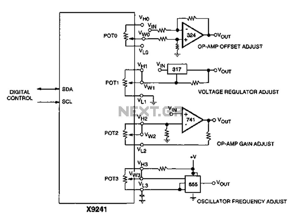
Corrector circuit diagram of an analog circuit
A XICOR X9241 POT IC module can be utilized to modify the four digital analog circuits, as depicted in the schematic.
The XICOR X9241 is a digital potentiometer integrated circuit designed for precise adjustment of analog signal levels in various electronic...

Analog circuit enforces slow servo response
The all-analog circuit presented controls the rate at which a miniature turbojet engine can be throttled. Increasing or decreasing the throttle too quickly on a miniature turbojet engine, or any jet engine, can lead to quick failure in flight, causing...

Proximity switch integrated circuit composed of the magnetic field sensor HMC1001
The circuit depicted in the figure includes the HMC1001 magnetic sensor, an operational amplifier (AMP04), and a light-emitting diode (LED), forming a proximity switch circuit. In this application, the operational amplifier functions as a comparator. When a magnet, approximately 6mm...