


Combustible Gas Detector Circuit
#gas sensor
#combustible gas
#alarm
#comparator
#voltage divider
#safety
#detection
#buzzer
#tin dioxide

Description: The gas sensor primarily consists of tin dioxide mounted on a ceramic substrate. The sensor's resistance changes based on the concentration of reducing gases present in the air. The depicted circuit is effective for detecting hazardous levels of combustible fumes or gases. It employs a comparator circuit to activate an alarm buzzer. The sensor's resistive element is arranged in series with resistor R1 to create a voltage-divider configuration. R1 is tailored to each gas sensor by the manufacturer.
The gas sensor operates on the principle that the resistance of tin dioxide varies with the concentration of reducing gases, such as methane or propane. As the concentration of these gases increases, the sensor's resistance decreases, leading to a change in voltage across the voltage divider formed by the sensor and R1. This change in voltage is monitored by the comparator circuit.
The comparator circuit typically consists of an operational amplifier (op-amp) configured to compare the voltage from the voltage divider against a reference voltage. When the voltage from the sensor falls below the reference level, indicating a dangerous concentration of gas, the output of the op-amp switches states, triggering the alarm buzzer. This alert system is crucial for ensuring safety in environments where combustible gases may be present.
The choice of R1 is critical, as it must be specifically matched to the characteristics of the gas sensor to ensure accurate detection and response. The manufacturer provides this resistor value to optimize the performance of the sensor in its intended application. In addition to the basic components, the circuit may also include additional features such as LED indicators to visually signal the status of the sensor and alarm system, as well as potential filtering capacitors to stabilize the voltage readings and reduce noise.
Overall, the gas sensor circuit is a vital tool for monitoring air quality and ensuring safety in various applications, including residential, industrial, and commercial environments. The combination of the tin dioxide sensor, voltage divider, and comparator circuit provides a reliable method for detecting hazardous gas levels and activating alarms to alert users of potential dangers. THE GAS SENSOR is mainly composed of tin dioxide on a ceramic base; the resistance of the sensor varies depending on the concentration of reducing gases in the air. The circuit shown is useful for the detection of dangerous levels of combustible fumes or gases. It uses a comparator circuit to trigger an alarm buzzer. The sensor`s resistant element is connected in series with resistor R1 to form a voltage- divider circuit;
R1 is specifically matched to each gas sensor by the manufacturer.
The gas sensor operates on the principle that the resistance of tin dioxide varies with the concentration of reducing gases, such as methane or propane. As the concentration of these gases increases, the sensor's resistance decreases, leading to a change in voltage across the voltage divider formed by the sensor and R1. This change in voltage is monitored by the comparator circuit.
The comparator circuit typically consists of an operational amplifier (op-amp) configured to compare the voltage from the voltage divider against a reference voltage. When the voltage from the sensor falls below the reference level, indicating a dangerous concentration of gas, the output of the op-amp switches states, triggering the alarm buzzer. This alert system is crucial for ensuring safety in environments where combustible gases may be present.
The choice of R1 is critical, as it must be specifically matched to the characteristics of the gas sensor to ensure accurate detection and response. The manufacturer provides this resistor value to optimize the performance of the sensor in its intended application. In addition to the basic components, the circuit may also include additional features such as LED indicators to visually signal the status of the sensor and alarm system, as well as potential filtering capacitors to stabilize the voltage readings and reduce noise.
Overall, the gas sensor circuit is a vital tool for monitoring air quality and ensuring safety in various applications, including residential, industrial, and commercial environments. The combination of the tin dioxide sensor, voltage divider, and comparator circuit provides a reliable method for detecting hazardous gas levels and activating alarms to alert users of potential dangers. THE GAS SENSOR is mainly composed of tin dioxide on a ceramic base; the resistance of the sensor varies depending on the concentration of reducing gases in the air. The circuit shown is useful for the detection of dangerous levels of combustible fumes or gases. It uses a comparator circuit to trigger an alarm buzzer. The sensor`s resistant element is connected in series with resistor R1 to form a voltage- divider circuit;
R1 is specifically matched to each gas sensor by the manufacturer.

Combustible gas alarm circuit diagram 7812 7805 555
The circuit consists of a buck rectifier and voltage regulator, a gas sensor, a comparator circuit, and an alarm sound circuit. The buck regulator circuit includes a transformer, a bridge rectifier, and components such as QL, IC3 (7812), and IC4...

Nokia 5800 Ringtone Buzzer Audio IHF Speaker Repair
Before proceeding with these steps, ensure that the software calibration and the basic procedures for checking audio circuit components have been completed. The audio circuit schematic diagram is preferred for easy tracking, and this method will aid in future repair...

Hi-Low level comparator
The voltage to be compared is fed through diodes D1 and D2 to the voltage dividers R1 and R5, where the low and high limits are established. When the input signal voltage exceeds the high threshold limit set with potentiometer...

Explosive gas detector circuit diagram
A gas sensor (from Allegro Electronics, Cornwall Bridge, CT06754 Ts GS823) activates in the presence of explosive gas. U5 functions as a voltage-to-frequency converter, with the sensor producing a frequency that is proportional to conductance. The output frequency varies from...

Alcohol used to monitor gas concentration gas sensor circuit diagram
Ceramic gas sensors can be utilized to analyze the content of alcohol vapor. With the appropriate sensor circuit, it is possible to detect blood alcohol content. The operating principle is straightforward: if blood alcohol content is present in a certain...

Alarm interface circuit
Alarm interface circuitry featuring a two-color light-emitting diode (LED) display. When LAi is at a high level and LBi is low, the green LED lights up; conversely, if LAi is low and LBi is high, the red LED lights up....

Simple lock circuit can alarm
The circuit operates as illustrated in Figure 5-2a. It includes an alarm switch (S). When switch S is pressed, relay K is activated, which closes two normally open contacts. This action triggers the alarm bells. The alarm continues to sound...

Gas Leak Detector Circuit
A gas leak detector circuit that detects the leakage of LPG gas and alerts the user through audio-visual indications. The circuit operates off a 9V PP3 battery. A Zener diode is used to convert 9V into 5V DC to drive...
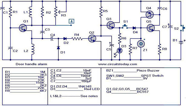
Door handle alarm
The automatic door handle alarm circuit emits an audible alarm and activates an LED when someone touches the door handle. This latching circuit continues to produce sound until it is manually turned off. Transistor Q1 is configured as an astable...