


Digital Compass
#digital compass
#Hall sensor
#logic gates
#NOR gates
#direction sensing
#magnetic field
#sensor output
#electronic navigation
#orientation detection

Description: A four-output Hall sensor combined with several logic gates produces this digital compass. The NOR gates resolve the four Hall outputs into eight distinct compass directions. LEDs to indicate direction are driven by eight inverters. A power supply for 5.25 to 18 Vdc operation is shown in the figure.
The digital compass circuit utilizes a four-output Hall effect sensor to detect magnetic fields and determine directional orientation. The sensor outputs are processed through a series of NOR gates, which serve to combine the four distinct outputs into eight unique states, effectively representing the eight cardinal and intercardinal directions (North, Northeast, East, Southeast, South, Southwest, West, and Northwest).
Each of the eight outputs from the NOR gates corresponds to a specific direction, illuminating an LED indicator for that direction. The LEDs are driven by inverters, which ensure that the output signal is suitable for activating the LEDs, providing a visual representation of the current heading.
The circuit is powered by a versatile power supply capable of operating within a range of 5.25 to 18 Vdc. This flexibility allows the digital compass to be integrated into various applications, from portable devices to fixed installations. The schematic design is crucial for ensuring the correct configuration of components, including the Hall sensor, NOR gates, inverters, and power supply connections, to achieve reliable performance in direction sensing.
In summary, this digital compass circuit exemplifies an efficient integration of sensor technology and digital logic to produce a user-friendly directional indicator, suitable for a wide range of electronic applications. A four output Hall sensor combined with a few logic gates produce this digital compass. The NOR gates resolve the four Hall outputs into eight distinct compass directions. LEDs to indicate direction are driven by eight inverters. A power supply for 5.25- to 18-Vdc operation is shown in the figure.
The digital compass circuit utilizes a four-output Hall effect sensor to detect magnetic fields and determine directional orientation. The sensor outputs are processed through a series of NOR gates, which serve to combine the four distinct outputs into eight unique states, effectively representing the eight cardinal and intercardinal directions (North, Northeast, East, Southeast, South, Southwest, West, and Northwest).
Each of the eight outputs from the NOR gates corresponds to a specific direction, illuminating an LED indicator for that direction. The LEDs are driven by inverters, which ensure that the output signal is suitable for activating the LEDs, providing a visual representation of the current heading.
The circuit is powered by a versatile power supply capable of operating within a range of 5.25 to 18 Vdc. This flexibility allows the digital compass to be integrated into various applications, from portable devices to fixed installations. The schematic design is crucial for ensuring the correct configuration of components, including the Hall sensor, NOR gates, inverters, and power supply connections, to achieve reliable performance in direction sensing.
In summary, this digital compass circuit exemplifies an efficient integration of sensor technology and digital logic to produce a user-friendly directional indicator, suitable for a wide range of electronic applications. A four output Hall sensor combined with a few logic gates produce this digital compass. The NOR gates resolve the four Hall outputs into eight distinct compass directions. LEDs to indicate direction are driven by eight inverters. A power supply for 5.25- to 18-Vdc operation is shown in the figure.

8-direction Digital Compass Using Z8 Encore
The M-8880 is a complete DTMF Transmitter/Receiver that features adjustable guard time, automatic tone burst mode, call progress mode, and a fully compatible 6500/6800 microprocessor interface. The receiver portion is based on the industry-standard M-8870 DTMF Receiver, while the transmitter...

B-Field Measurer
This circuit generates an output voltage that is proportional to the magnetic induction (B) detected by its probe's coil. The coil must be sized to produce a full-scale, 10-V output corresponding to the maximum expected intensity of magnetic induction. The...

Ground-Fault Hall Sensor
No electrical contact exists between the circuit and the conductor. The 7474 flip-flop is triggered by the output from the Hall sensor, op amp, and Schmitt trigger. This triggering activates the optocoupler, turns on the triac, and trips the circuit...
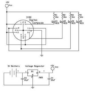
1490 Digital Compass
The first test circuit is one of the simplest designs that can be created around the device. The sensor is depicted in the schematic as if viewed from above, showing the 12 leads below. The circuit incorporates four LEDs for...

Magnetic Field Sensor Circuit
This DIY magnetic field sensor circuit is straightforward and capable of detecting both static magnetic fields and those that vary at audio frequencies. The unit is designed to be user-friendly and efficient.
The magnetic field sensor circuit typically employs a Hall...

Logic Circuits Vs Transistor Power Circuits
Invert a signal to drive FETs with rapid rise and fall times. It was suggested to use an inverter (not a chip) instead of logic chips, which are designed to be either fully ON or OFF. The individual has prior...

magnetic field therapy
Devices capable of disabling and destroying microorganisms, including viruses, bacteria, and fungi, utilize pulsed, intense magnetic fields. These devices are not futuristic concepts but are currently available and employed in the alternative health field. Various claims exist regarding their effectiveness,...

Magnetic Field Sensor circuit
This DIY magnetic field sensor circuit is straightforward and capable of detecting both fixed magnetic fields and those that vary at audio frequencies. The device is not designed for precise measurement of magnetic field strength. A small and relatively weak...
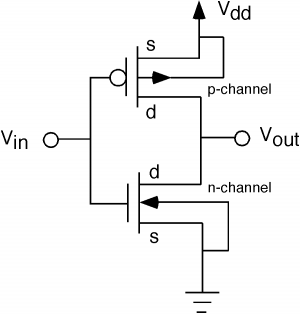
When abstract logic circuits get translated to the electrical equivilant how are conversions from 0 to 1 handled
The fundamental issue presented is the perception that logic gates in a circuit seem to generate power from nothing, which contradicts the principles of physics. For instance, consider two NOT gates connected in series. It appears that the first NOT...