


Easy Pulse: A DIY photoplethysmographic sensor for measuring heart rate. Part 1 - Theory and Schemat
#photoplethysmography
#heart rate sensor
#infrared LED
#photodiode
#biomedical
#DIY
#health monitoring
#optical sensor
#fingertip sensor

Description: The heart rate measurement project utilizing fingertip photoplethysmography was constructed using salvaged components, specifically an infrared LED and a photodiode. Due to the nature of these parts, their specifications could not be provided in the article.
The heart rate measurement system based on fingertip photoplethysmography operates by analyzing blood volume changes in the fingertip, which are detected through light absorption characteristics. The core components of this system include an infrared LED, which emits light that penetrates the skin, and a photodiode, which senses the light that is reflected back.
In this project, the infrared LED emits light at a wavelength typically around 940 nm, which is optimal for penetrating human tissue and minimizing interference from ambient light. The photodiode is positioned to receive the light that is reflected from the fingertip, where variations in blood volume during each heartbeat alter the amount of light absorbed versus reflected.
The circuit design includes a current-limiting resistor in series with the infrared LED to prevent excessive current flow, ensuring the longevity of the component. The photodiode is connected to an operational amplifier configured as a transimpedance amplifier, which converts the small current generated by the photodiode into a measurable voltage signal. This voltage signal is then processed by a microcontroller or an analog-to-digital converter (ADC) to calculate the heart rate.
To enhance the accuracy of the measurements, additional circuit elements such as filters may be implemented to reduce noise and improve the signal-to-noise ratio. A low-pass filter can be used to smooth out high-frequency noise, while a high-pass filter may help eliminate baseline wander caused by motion artifacts.
Overall, the heart rate measurement circuit is a practical application of photoplethysmography, showcasing how salvaged components can be effectively utilized to create a functional health monitoring device.When I first built the Heart rate measurement through fingertip project, the infrared LED and photodiode used for finger photoplethysmography were actually from salvaged parts, and therefore, I could not provide specifications for them in the article. As a result of that it takes quite a bit of.
The heart rate measurement system based on fingertip photoplethysmography operates by analyzing blood volume changes in the fingertip, which are detected through light absorption characteristics. The core components of this system include an infrared LED, which emits light that penetrates the skin, and a photodiode, which senses the light that is reflected back.
In this project, the infrared LED emits light at a wavelength typically around 940 nm, which is optimal for penetrating human tissue and minimizing interference from ambient light. The photodiode is positioned to receive the light that is reflected from the fingertip, where variations in blood volume during each heartbeat alter the amount of light absorbed versus reflected.
The circuit design includes a current-limiting resistor in series with the infrared LED to prevent excessive current flow, ensuring the longevity of the component. The photodiode is connected to an operational amplifier configured as a transimpedance amplifier, which converts the small current generated by the photodiode into a measurable voltage signal. This voltage signal is then processed by a microcontroller or an analog-to-digital converter (ADC) to calculate the heart rate.
To enhance the accuracy of the measurements, additional circuit elements such as filters may be implemented to reduce noise and improve the signal-to-noise ratio. A low-pass filter can be used to smooth out high-frequency noise, while a high-pass filter may help eliminate baseline wander caused by motion artifacts.
Overall, the heart rate measurement circuit is a practical application of photoplethysmography, showcasing how salvaged components can be effectively utilized to create a functional health monitoring device.When I first built the Heart rate measurement through fingertip project, the infrared LED and photodiode used for finger photoplethysmography were actually from salvaged parts, and therefore, I could not provide specifications for them in the article. As a result of that it takes quite a bit of.

A contact-less digital tachometer based on optical sensors
The circuit for the Digital Tachometer/RPM Counter consists of only a few devices. Wire them up according to the following circuit diagram. The PIC used is on a demonstration board, which means the clock, power, and ground pins are already...

Homemade Metal Detector Kit
A simple home project can quickly become problematic if it encounters electric cables, gas, or water pipes, or the central heating system. Using a metal detector allows one to check for metal objects within walls, ceilings, or floors beforehand. An...

Precision photodiode level detector
The output state changes at a photodiode current of 0 µA. For R1 = 2 MΩ, R2 = R3 = 5 MΩ.
The described circuit likely involves a photodiode used in conjunction with resistors R1, R2, and R3 to create a...
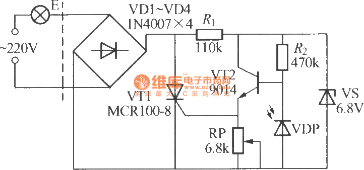
Simple light-operated street lamp circuit diagram(3)
The VDP is a photodiode that exhibits low resistance during the day, approximately 1 kΩ. As a result, transistor VT2 remains off, which keeps thyristor VT1 in the off-state due to the absence of trigger current at the gate, preventing...

5 Minute Signal
For the past year and a half, a group based in Ann Arbor, Michigan, named GO-Tech has been formed, uniting individuals interested in creating projects using technology, such as hardware, software, metal, and wood. This initiative is referred to as...

Precision photodiode comparator
Rl sets the comparison level. At comparison, the photodiode has less than 5 mV across it, decreasing dark current by an order of magnitude. More: IC = LM 111/211/311.
In this circuit description, the resistor Rl plays a crucial role in...

Crescendo ampilifier elektor1982
The Elector Crescendo was the first DIY amplifier that was not a kit. The design was sourced from the Elector magazines available at a local library.
The Elector Crescendo is an innovative audio amplifier designed for DIY enthusiasts. It features a...

Optical Interruption Sensor
Using only an 8-pin integrated circuit (IC) and a few discrete components, an infrared optical interrupter can be constructed. The NE567 tone decoder includes all necessary circuit elements: a local oscillator, a phase-locked loop (PLL) decoder, and a 100-mA output...

Photoreceiving circuit diagram LM307 amplifier configuration
The circuit described is a photoelectric receiver amplifier designed to amplify the electrical signals generated by photodiodes or phototransistors in optoelectronic devices. When the intensity of incident light varies, the photosensitive device generates a corresponding voltage or current. The photoreceptor...