


Line-Following Mini-Tank - Schematic
#line-following
#accelerometer
#voltage regulator
#motor control
#7-segment LED
#battery
#A/D converter
#tank robot
#sensor circuitry
#power circuit

Description: The schematic consists of three main components. The first component is the sensor circuitry, which connects the accelerometer to the analog-to-digital converters (A/D converters). The second component is the power circuit, featuring an On/Off switch, a 3.7V battery, and a +5V 7805 voltage regulator. The third component includes three 7-segment LEDs. The motor circuit is responsible for controlling the motors based on the sensor data received from the analog brain circuit. The two motors operate at 3V and can achieve moderate speeds. A diode is connected between the motors and the battery, which reduces the voltage supplied to the motors, thereby slightly slowing them down. Additionally, an infrared (IR) emitter LED and a phototransistor are utilized for detecting white or black colors. The LED emits IR light, while the phototransistor detects the reflected IR light, allowing the circuit to identify the type of light reflected from a surface. This section of the circuit integrates the sensor and motor circuits, enabling the robot to perform its functions. A small application-specific integrated circuit (ASIC) logic is employed to process incoming sensor signals and determine which motor should be activated and at what time.
The schematic can be divided into three primary sections, each serving a specific function essential for the overall operation of the system.
The sensor circuitry is crucial as it interfaces with an accelerometer, which measures acceleration forces. This data is converted into a digital format by the A/D converters, allowing for precise processing of sensor information. The design of this section must ensure minimal noise interference to maintain accurate readings, which may involve the use of filtering capacitors and proper grounding techniques.
The power circuit is designed to provide stable voltage levels necessary for the operation of all components. The inclusion of a 3.7V rechargeable lithium battery ensures that the system can operate independently without external power. The 7805 voltage regulator is employed to step down the voltage to +5V, which is essential for powering digital components such as the A/D converters and microcontrollers. The On/Off switch allows for convenient control of the entire system, ensuring energy conservation when the device is not in use.
The motor circuit plays a pivotal role in executing the physical actions of the robot. With two 3V motors, the design allows for moderate-speed movement. The diode in the circuit serves a dual purpose: it not only protects the circuit from back EMF generated by the motors when they are turned off but also reduces the voltage supplied to the motors, effectively controlling their speed.
The integration of the IR emitter LED and phototransistor is vital for surface detection. The IR emitter projects light onto surfaces, and the phototransistor detects the intensity of the reflected light, allowing the system to distinguish between different colors or surfaces. This feedback is essential for the robot's navigation and operational capabilities.
Finally, the ASIC logic provides a compact and efficient means of processing sensor data. It interprets the signals from the sensor circuitry and determines the appropriate motor actions based on predefined logic. This allows for real-time response to environmental changes, enhancing the robot's functionality and adaptability.
Overall, the schematic is a well-coordinated assembly of components that work together to create an intelligent robotic system capable of responding to its environment effectively.The Schematic has three main parts to it. The Sensor Circuitry where the accelerometer is wired up to the A/D converters. The second part is the power circuit where we have the On/Off switch, the 3. 7v battery & +5v 7805 Voltage Regualtor. The 3rd part of the circuit is the 3 7-Segment LEDs. The motor circuit controls the motors depending on the s ensor data that comes in through the `analog brain` circuit. The two motors are 3v and can move moderatley fast. The diode that connects the motors to the battery reduces the voltage at the motors which slows them down a little bit. The IR Emitter LED and Phototransistor are used for sensing white or black color. The LED emits IR light and the phototransistor receives IR light. Together they work well at see what type of light if any is reflected from a surface. This part of the circuit connects the sensor circuit and the motor circuit together so that the robot can do its job.
A little ASIC logic is used to transfer incoming sensor signals into which motor should be turned on and when.
The schematic can be divided into three primary sections, each serving a specific function essential for the overall operation of the system.
The sensor circuitry is crucial as it interfaces with an accelerometer, which measures acceleration forces. This data is converted into a digital format by the A/D converters, allowing for precise processing of sensor information. The design of this section must ensure minimal noise interference to maintain accurate readings, which may involve the use of filtering capacitors and proper grounding techniques.
The power circuit is designed to provide stable voltage levels necessary for the operation of all components. The inclusion of a 3.7V rechargeable lithium battery ensures that the system can operate independently without external power. The 7805 voltage regulator is employed to step down the voltage to +5V, which is essential for powering digital components such as the A/D converters and microcontrollers. The On/Off switch allows for convenient control of the entire system, ensuring energy conservation when the device is not in use.
The motor circuit plays a pivotal role in executing the physical actions of the robot. With two 3V motors, the design allows for moderate-speed movement. The diode in the circuit serves a dual purpose: it not only protects the circuit from back EMF generated by the motors when they are turned off but also reduces the voltage supplied to the motors, effectively controlling their speed.
The integration of the IR emitter LED and phototransistor is vital for surface detection. The IR emitter projects light onto surfaces, and the phototransistor detects the intensity of the reflected light, allowing the system to distinguish between different colors or surfaces. This feedback is essential for the robot's navigation and operational capabilities.
Finally, the ASIC logic provides a compact and efficient means of processing sensor data. It interprets the signals from the sensor circuitry and determines the appropriate motor actions based on predefined logic. This allows for real-time response to environmental changes, enhancing the robot's functionality and adaptability.
Overall, the schematic is a well-coordinated assembly of components that work together to create an intelligent robotic system capable of responding to its environment effectively.The Schematic has three main parts to it. The Sensor Circuitry where the accelerometer is wired up to the A/D converters. The second part is the power circuit where we have the On/Off switch, the 3. 7v battery & +5v 7805 Voltage Regualtor. The 3rd part of the circuit is the 3 7-Segment LEDs. The motor circuit controls the motors depending on the s ensor data that comes in through the `analog brain` circuit. The two motors are 3v and can move moderatley fast. The diode that connects the motors to the battery reduces the voltage at the motors which slows them down a little bit. The IR Emitter LED and Phototransistor are used for sensing white or black color. The LED emits IR light and the phototransistor receives IR light. Together they work well at see what type of light if any is reflected from a surface. This part of the circuit connects the sensor circuit and the motor circuit together so that the robot can do its job.
A little ASIC logic is used to transfer incoming sensor signals into which motor should be turned on and when.

Voltage Regulator
This regulator is suitable for devices that need up to 1mA. For higher output current, the resistors would have to be scaled down in reverse proportion to the peak current expected. With the resistor values shown, the regulator draws a...

Car battery condition checker
This circuit utilizes an LED and a 4081 CMOS integrated circuit. A variable resistor is employed to adjust the voltage threshold at which the LED activates. The control should be set so that the LED illuminates when the voltage from...

motor control inverter (AC drive) in mine industry
Motor control, energy efficiency of inverter (AC drive) selection, and parameters setting guidance in the mining industry: vector control, open loop or closed loop control, with energy braking unit or energy feedback unit.
In the context of motor control for the...

Cyclic A/D converter circuit
The cyclic converter is composed of a series of identical stages, each stage detecting the polarity of the input. The reference voltage, V_REF, is subtracted from the double entry, and the remaining value is processed if the polarity is correct....

Power Supply for Battery Valve Radios
Many later radios utilize four 7-pin valves and require a high tension (HT) supply of 90V at approximately 12mA, and a low tension (LT) supply of either 125mA or 250mA, depending on the specific valves used. The original batteries for...
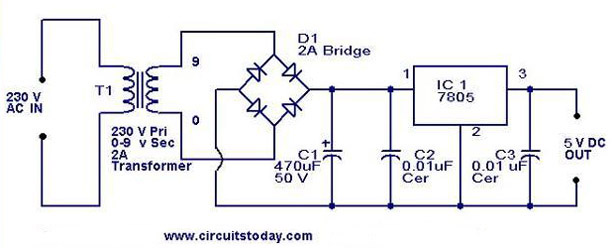
5V power supply using 7805 IC with circuit diagram
A 5V power supply using IC 7805 is designed and explained with a neat circuit diagram.
The circuit for a 5V power supply utilizing the IC 7805 voltage regulator is a straightforward and efficient design that provides a stable output voltage...

SciTech PS-3R Power Supply Circuit
The following circuit illustrates the SciTech PS-3R Power Supply Circuit. Features include 13.8V DC output, 5 Amps surge capability, and a constant output of 3 Amps. Components include a transistor and others.
The SciTech PS-3R Power Supply Circuit is designed to...

Voltage regulator or resistors to change voltages for motors
After conducting some research, it was found that voltage can be adjusted using either a voltage regulator chip or resistors. Several scenarios require reducing the voltage for motors, prompting a question about the appropriate method for each application. An H-Bridge...

The Accelerometer Circuit
The schematic for this tutorial is straightforward. It involves connecting the ADXL320 sensor to the PIC microcontroller and an LED. The power supply is assumed to be a +5V battery to power the PIC. A custom power circuit can be...