


live line detector indicator circuit schematic
#live line detector
#capacitive coupling
#4017 IC
#LED indicator
#50Hz frequency
#mains voltage
#non-contact detection
#safety
#electrical
#flashing LED
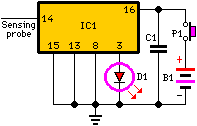
Description: When the unit is positioned near a live conductor, whether insulated or buried in plaster, capacitive coupling occurs between the live conductor and the probe. This interaction activates the counter, resulting in the LED flashing five times per second, as the 4017 integrated circuit divides the 50Hz mains frequency by ten. When the unit is moved away from a live line, counting ceases, and the LED remains permanently off.
The described circuit utilizes a 4017 decade counter integrated circuit to detect the presence of an alternating current (AC) signal induced via capacitive coupling. The circuit is designed to operate in proximity to live conductors, allowing for non-invasive detection of electrical signals without direct contact.
The core of the system is built around the 4017 IC, which is a decade counter that counts from 0 to 10. The input to the counter is derived from the capacitive coupling of the probe to the live conductor. As the unit approaches an AC source, the capacitive coupling generates a small AC voltage at the input of the 4017, which triggers the counting mechanism. The frequency of the AC mains supply is typically 50Hz, and the 4017 divides this frequency by ten, resulting in a counting frequency of 5Hz. This output is used to drive an LED indicator, which flashes at this rate, providing a visual indication of the presence of the live conductor.
When the unit is moved away from the live conductor, the capacitive coupling diminishes, leading to the cessation of the input signal to the 4017. Consequently, the counter stops counting, and the LED indicator remains off, indicating that there is no longer a live signal detected in the vicinity.
The design of this circuit emphasizes safety and non-contact measurement, making it suitable for applications where direct electrical contact is impractical or dangerous. Additional components may include resistors to limit current to the LED and capacitors to filter the signal, ensuring stable operation and accurate detection. Proper layout and shielding techniques may also be employed to minimize interference and enhance the sensitivity of the probe.If the unit is brought close to a live conductor (insulated, and even buried in plaster) capacitive coupling between the live conductor and the probe clocks the counter, and causes the LED to flash 5 times per second, because the 4017 IC divides the mains 50Hz frequency by 10. When remote from a live line, the unit stops counting, the LED resulting permanently off..
The described circuit utilizes a 4017 decade counter integrated circuit to detect the presence of an alternating current (AC) signal induced via capacitive coupling. The circuit is designed to operate in proximity to live conductors, allowing for non-invasive detection of electrical signals without direct contact.
The core of the system is built around the 4017 IC, which is a decade counter that counts from 0 to 10. The input to the counter is derived from the capacitive coupling of the probe to the live conductor. As the unit approaches an AC source, the capacitive coupling generates a small AC voltage at the input of the 4017, which triggers the counting mechanism. The frequency of the AC mains supply is typically 50Hz, and the 4017 divides this frequency by ten, resulting in a counting frequency of 5Hz. This output is used to drive an LED indicator, which flashes at this rate, providing a visual indication of the presence of the live conductor.
When the unit is moved away from the live conductor, the capacitive coupling diminishes, leading to the cessation of the input signal to the 4017. Consequently, the counter stops counting, and the LED indicator remains off, indicating that there is no longer a live signal detected in the vicinity.
The design of this circuit emphasizes safety and non-contact measurement, making it suitable for applications where direct electrical contact is impractical or dangerous. Additional components may include resistors to limit current to the LED and capacitors to filter the signal, ensuring stable operation and accurate detection. Proper layout and shielding techniques may also be employed to minimize interference and enhance the sensitivity of the probe.If the unit is brought close to a live conductor (insulated, and even buried in plaster) capacitive coupling between the live conductor and the probe clocks the counter, and causes the LED to flash 5 times per second, because the 4017 IC divides the mains 50Hz frequency by 10. When remote from a live line, the unit stops counting, the LED resulting permanently off..

Contactless Live Line Detector
A live-line detector is a circuit designed to identify the presence of a live mains conductor through capacitive coupling between the live conductor and the detection circuit.
The live-line detector operates on the principle of capacitive coupling, which allows it to...

Mains voltage bidirectional limit alarm protection circuit diagram
The alarm protection can trigger a sound and light alert when the mains voltage exceeds or falls below a predetermined threshold. It automatically disconnects the electrical power supply without damaging the electrical protection. The device is compact, fully featured, and...

Mains Voltage Checker
This is a CMOS IC (CD4033) based circuit which can be used to detect presence of mains AC voltage without any electrical contact with the conductor carrying AC current/voltage. Thus it can be used to detect mains AC voltage without...

Mains Voltage Detector
The detector is designed to sense and signal to another circuit when an appliance is connected to the mains voltage. For this purpose, an optocoupler, IC1, is utilized.
The circuit employs an optocoupler (IC1) to provide electrical isolation between the high-voltage...

Test wall socket with current limiting
Individuals who frequently build, repair, and test equipment powered by mains voltage may encounter unexpected hazards, such as loud explosions, equipment destruction, flying components, tripped circuit breakers, and power outages. These incidents can be mitigated by utilizing a test wall...

mains voltage detector
The detector is designed to sense and signal to another circuit when an appliance is connected to the mains voltage. An optocoupler, identified as IC1 in the circuit, is utilized for this purpose. The light-emitting diode within the optocoupler is...

mains pulse circuit
This circuit is designed to control the mains voltage by switching it on and off at intervals ranging from just under a second to up to 10 minutes. It is particularly useful for testing mains-operated equipment over extended periods or...
Live line Detector
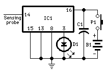
Detects the presence of a live mains conductor. Minimum parts counting. If the unit is brought close to a live conductor (insulated, and even buried in plaster) capacitive coupling between the live conductor and the probe clocks the counter, and...

Night Safety Light For Autos
This circuit activates the brake lights of a parked car when headlights from an approaching vehicle are detected, alerting the driver of the oncoming vehicle about the stationary car. LDR4 serves as the sensor, while LDR1 deactivates the circuit by...