


o2 sensor
#oxygen sensor
#protoboard
#cigarette lighter plug
#adjustment knob
#indicator LED
#voltage drop
#schematic diagram
#simulator

Description: The oxygen sensor simulator is constructed on a protoboard. It utilizes a cigarette lighter plug as the power source. An adjustment knob is located on the left side, while a switch is positioned on the right. A red indicator LED is centered in the design. Only a red LED should be used, as its voltage drop is integral to the circuit. The schematic diagram for the simulator indicates that closing the switch activates the simulator. Turning the knob clockwise simulates a lean condition, which turns the LED off and prompts the vehicle to run rich in compensation. The large "V" represents a digital voltmeter (not depicted in the images). Employing a smaller capacitance value for C1, such as 4.7 µF, will increase the circuit's oscillation frequency, thereby mimicking the behavior of a new oxygen sensor that switches more frequently than an older one.
The oxygen sensor simulator is a crucial tool for testing and diagnosing automotive engine management systems. It is designed to emulate the electrical characteristics of a real oxygen sensor, allowing for the evaluation of fuel mixture adjustments in response to varying conditions. The device operates by simulating a lean or rich air-fuel mixture, which is essential for tuning the engine's performance.
The protoboard setup facilitates easy modifications and adjustments, making it suitable for experimental purposes. The use of a cigarette lighter plug for power supply ensures compatibility with most vehicles, allowing for straightforward connection and operation. The adjustment knob provides a user-friendly interface to simulate different operating conditions. When the knob is rotated clockwise, it simulates a lean condition by reducing the output voltage, which in turn turns off the LED indicator. This behavior is representative of how an actual oxygen sensor would operate under similar conditions, prompting the engine control unit (ECU) to enrich the fuel mixture to maintain optimal combustion.
The inclusion of a digital voltmeter, although not shown in the images, is a vital feature that allows for real-time monitoring of the voltage output from the simulator. This feedback can be invaluable for diagnosing issues within the engine management system.
The choice of a red LED is significant; its forward voltage drop is accounted for in the circuit design, ensuring that the simulator operates correctly under varying conditions. Adjusting the capacitance of C1 can significantly impact the circuit's response time. A lower capacitance value, such as 4.7 µF, increases the oscillation frequency, allowing the simulator to more accurately replicate the rapid switching behavior of a new oxygen sensor. This adjustment can provide more precise simulation results, making the device more effective for testing purposes.
Overall, the oxygen sensor simulator serves as an essential diagnostic tool, providing valuable insights into the performance and behavior of automotive fuel management systems. Its design allows for flexibility and adaptability, making it suitable for both educational and practical applications in the field of automotive electronics.The oxygen sensor simulator as built on a protoboard. Note the cigarette lighter plug used for power source. The adjustment knob is at the left, and the switch is on the right. The red indicator LED is in the middle. Only use red, because the voltage drop of the LED is part of the circuit! The schematic diagram for the simulator. Closing the switc h engages the simulator. Turning the knob clockwise simulates a lean condition, turns the LED off, and the car should start running rich to compensate. The big "V" is a digital voltmeter(not shown in the pictures). Using a smaller value for C1, perhaps 4. 7 uF, will make the circuit oscillate faster and might be more like a real oxygen sensor(a new sensor switches more often than an old one).
The oxygen sensor simulator is a crucial tool for testing and diagnosing automotive engine management systems. It is designed to emulate the electrical characteristics of a real oxygen sensor, allowing for the evaluation of fuel mixture adjustments in response to varying conditions. The device operates by simulating a lean or rich air-fuel mixture, which is essential for tuning the engine's performance.
The protoboard setup facilitates easy modifications and adjustments, making it suitable for experimental purposes. The use of a cigarette lighter plug for power supply ensures compatibility with most vehicles, allowing for straightforward connection and operation. The adjustment knob provides a user-friendly interface to simulate different operating conditions. When the knob is rotated clockwise, it simulates a lean condition by reducing the output voltage, which in turn turns off the LED indicator. This behavior is representative of how an actual oxygen sensor would operate under similar conditions, prompting the engine control unit (ECU) to enrich the fuel mixture to maintain optimal combustion.
The inclusion of a digital voltmeter, although not shown in the images, is a vital feature that allows for real-time monitoring of the voltage output from the simulator. This feedback can be invaluable for diagnosing issues within the engine management system.
The choice of a red LED is significant; its forward voltage drop is accounted for in the circuit design, ensuring that the simulator operates correctly under varying conditions. Adjusting the capacitance of C1 can significantly impact the circuit's response time. A lower capacitance value, such as 4.7 µF, increases the oscillation frequency, allowing the simulator to more accurately replicate the rapid switching behavior of a new oxygen sensor. This adjustment can provide more precise simulation results, making the device more effective for testing purposes.
Overall, the oxygen sensor simulator serves as an essential diagnostic tool, providing valuable insights into the performance and behavior of automotive fuel management systems. Its design allows for flexibility and adaptability, making it suitable for both educational and practical applications in the field of automotive electronics.The oxygen sensor simulator as built on a protoboard. Note the cigarette lighter plug used for power source. The adjustment knob is at the left, and the switch is on the right. The red indicator LED is in the middle. Only use red, because the voltage drop of the LED is part of the circuit! The schematic diagram for the simulator. Closing the switc h engages the simulator. Turning the knob clockwise simulates a lean condition, turns the LED off, and the car should start running rich to compensate. The big "V" is a digital voltmeter(not shown in the pictures). Using a smaller value for C1, perhaps 4. 7 uF, will make the circuit oscillate faster and might be more like a real oxygen sensor(a new sensor switches more often than an old one).

Download NL5 Non-Linear Electronic Circuit Simulator
Since then, NL has evolved into the Microsoft Windows®-based NL4, which has been extensively used by world-class engineers in various fields of electronics for almost 10 years. NL5 is the first version to be publicly available. Unlike conventional SPICE-based simulators,...

Portable hypoxia monitoring circuit ICL7660 PC254A PC153A
The portable hypoxia monitoring circuit comprises the oxygen sensor OS-12, a DC amplifier IC1, an A/D converter IC4, and a liquid crystal display F2100-34PI. Additionally, it includes a voltage comparator IC2 and a positive and negative power converter IC, along...

schematic monitor
A schematic diagram in hard copy related to the computer CSIRAC, possibly dated 1961. This schematic diagram illustrates the detailed connections between all the components in the circuit. Such diagrams were utilized for circuit construction and subsequent testing. For CSIRAC,...

Wearable hypoxia monitoring circuit design
The circuit principle involves an oxygen sensor circuit utilizing the OS-12, a DC amplifier IC1, an A/D converter IC4, a liquid crystal display F2100-34PI, a voltage comparator IC2, and a positive and negative power converter IC, among other components. The...

O2 Input 0-5v Modification
Software available on PGM-Fi.org and from Hondata utilizes the Honda ECU's oxygen sensor input to facilitate real-time display and data logging of wideband oxygen sensors. This process involves connecting the analog output from the wideband sensor's controller to the stock...

oxygen sensor tester circuit board
A 12V power supply is connected to the positive terminal, allowing current to flow through a protection diode and a capacitor that smooths the voltage. A zener resistor (R5) limits the current to the zener diode, which regulates the voltage...

HOW TO make a cheap narrowband A/F gauge
The engine management system monitors its air-fuel ratio using an oxygen sensor (O2) located in the hot exhaust flow, typically positioned before the catalytic converter. All O2 sensors function similarly, with variations including heated sensors or those with multiple signal...
schematic computer arithmetic organ
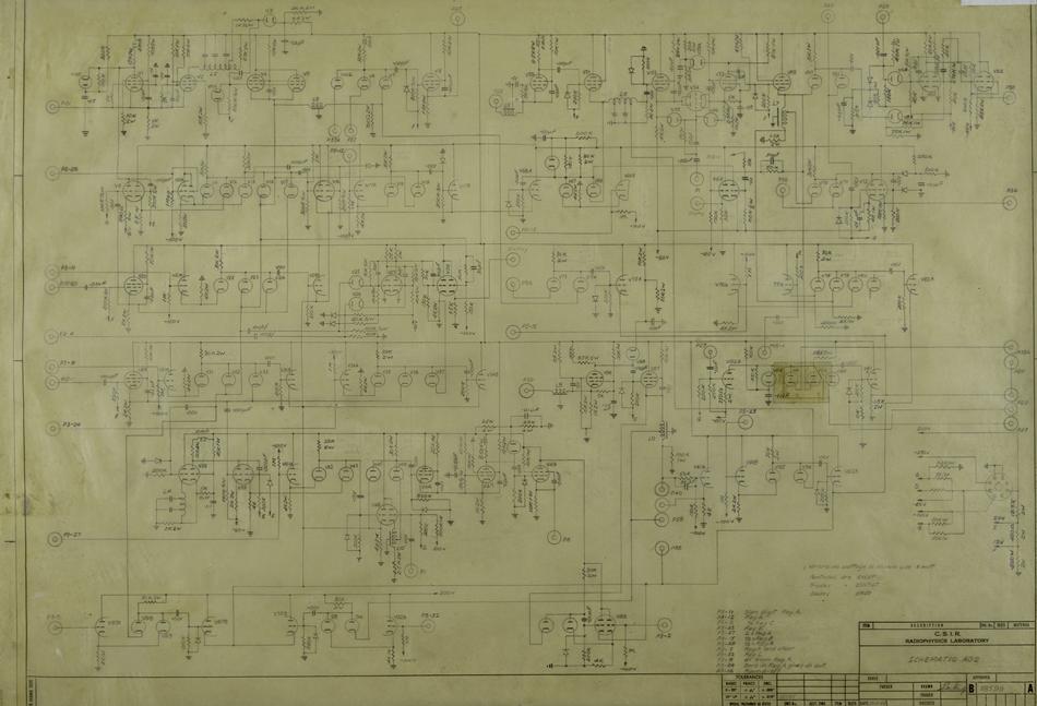
A schematic diagram illustrates the detailed connections between all components in a circuit. These diagrams are utilized for circuit construction and subsequent testing. In the case of CSIRAC, the primary components included vacuum tubes (valves), capacitors, and resistors. Schematic diagrams...

Micro-Cap 9
Micro-Cap 9 is an integrated schematic editor and mixed analog/digital simulator that provides an interactive sketch and simulate environment for electronics engineers. Since its original release in 1982, Micro-Cap has been steadily expanded and improved. Micro-Cap 9, the eighth generation,...