


Whistle Switch
#whistle switch
#sound sensor
#appliance control
#audio detection
#switch circuit
#home automation
#vintage electronics
#modern components
#DIY project

Description: The whistle switch allows you to turn on, or off, an appliance by whistling at it. I originally built the whistle switch in 1974. Do not attempt to duplicate it from the schematic below, but instead, understand the functions and duplicate these functions with more modern components. More: The audio amp, after the microphone, should have enough gain to produce square waves from input noise. The LC tuned circuit can be replaced by an active bandpass filter, at the frequency that you whistle the easiest. The detector has a slow attach, fast d
The whistle switch operates by detecting audio signals, specifically the sound of a whistle, and using these signals to control an appliance. The core functionality involves several key components: a microphone, an audio amplifier, a frequency-selective circuit, and a control mechanism for the appliance.
The microphone captures the sound waves produced by a whistle. It is essential that the microphone is sensitive enough to pick up the specific frequency of the whistle. Following the microphone, an audio amplifier is employed to boost the microphone's output. This amplifier must be designed to provide sufficient gain to convert the relatively weak audio signal into a stronger signal that can be processed further. The output of the audio amplifier should ideally produce square wave signals from the input noise to ensure that the subsequent stages can effectively detect the whistle sound.
Instead of using an LC tuned circuit, which can be bulky and less flexible, an active bandpass filter can be integrated. This filter is tuned to the frequency range where the user typically whistles, allowing for more effective noise filtering and enhancing the detection of the desired signal. The active bandpass filter can be constructed using operational amplifiers and passive components, providing a compact solution that can be easily adjusted for different whistle frequencies.
The detection mechanism should incorporate a comparator or a microcontroller that can interpret the filtered signals. The comparator compares the amplified and filtered signal against a predefined threshold to determine if a whistle has occurred. The detector's response time is critical; it should have a slow attach time to avoid false triggering from transient noises while maintaining a fast release time to ensure that the appliance can be turned off quickly after the whistle ceases.
Finally, the output from the detector can be connected to a relay or a transistor switch that controls the appliance. This stage must be capable of handling the power requirements of the appliance being controlled, ensuring safe and reliable operation.
In summary, the modern whistle switch design can enhance the original concept by utilizing contemporary components such as active filters and microcontrollers, improving performance and reliability while maintaining the core functionality of the original design.The whistle switch allows you to turn on, or off, an appliance by whistling at it. I originally built the whistle switch in 1974. Do not attempt to duplicate it from the schematic below, but instead, understand the functions and duplicate these functions with more modern components. The audio amp, after the microphone, should have enough gain to produce square waves from input noise. The LC tuned circuit can be replaced by an active bandpass filter, at the frequency that you whistle the easiest.
The detector has a slow attach, fast d
The whistle switch operates by detecting audio signals, specifically the sound of a whistle, and using these signals to control an appliance. The core functionality involves several key components: a microphone, an audio amplifier, a frequency-selective circuit, and a control mechanism for the appliance.
The microphone captures the sound waves produced by a whistle. It is essential that the microphone is sensitive enough to pick up the specific frequency of the whistle. Following the microphone, an audio amplifier is employed to boost the microphone's output. This amplifier must be designed to provide sufficient gain to convert the relatively weak audio signal into a stronger signal that can be processed further. The output of the audio amplifier should ideally produce square wave signals from the input noise to ensure that the subsequent stages can effectively detect the whistle sound.
Instead of using an LC tuned circuit, which can be bulky and less flexible, an active bandpass filter can be integrated. This filter is tuned to the frequency range where the user typically whistles, allowing for more effective noise filtering and enhancing the detection of the desired signal. The active bandpass filter can be constructed using operational amplifiers and passive components, providing a compact solution that can be easily adjusted for different whistle frequencies.
The detection mechanism should incorporate a comparator or a microcontroller that can interpret the filtered signals. The comparator compares the amplified and filtered signal against a predefined threshold to determine if a whistle has occurred. The detector's response time is critical; it should have a slow attach time to avoid false triggering from transient noises while maintaining a fast release time to ensure that the appliance can be turned off quickly after the whistle ceases.
Finally, the output from the detector can be connected to a relay or a transistor switch that controls the appliance. This stage must be capable of handling the power requirements of the appliance being controlled, ensuring safe and reliable operation.
In summary, the modern whistle switch design can enhance the original concept by utilizing contemporary components such as active filters and microcontrollers, improving performance and reliability while maintaining the core functionality of the original design.The whistle switch allows you to turn on, or off, an appliance by whistling at it. I originally built the whistle switch in 1974. Do not attempt to duplicate it from the schematic below, but instead, understand the functions and duplicate these functions with more modern components. The audio amp, after the microphone, should have enough gain to produce square waves from input noise. The LC tuned circuit can be replaced by an active bandpass filter, at the frequency that you whistle the easiest.
The detector has a slow attach, fast d

Computerize Your Room/House
You have read about computerized rooms or seen home automation products advertised in electronics magazines. You have decided to try it yourself. However, it is important to note that this project is not inexpensive. A computer is required, which is...

Chicken male and female discriminator 1
The male and female chicken discriminator circuit comprises an audio detection circuit, an active band-pass filter, and an LED display circuit, as illustrated in Figure 4-11. The audio detection circuit consists of a piezoelectric ceramic element (BC) and resistors R1...

Whistle Switch Circuit
The whistle switch features two tone detectors, each based on an LM567 tone decoder, requiring minimal additional components. It is designed to respond to two or more occurrences of a specific tone or sequence of tones within a defined time...

sound origin direction finder
A sound origin direction indicator features a flat square shape with four sound transducer/amplifier units positioned at each corner. It includes four rows of solid-state lamps extending from the center to the corners and an electronic system integrated with the...
Sound Sensor
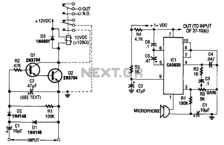
A sound-detecting alarm system can be constructed using a microphone, a high-gain amplifier, and a detector-relay driver. For a latching setup, connect the dotted lines to the relay as indicated in the schematic.
The sound-detecting alarm system utilizes a microphone to...
Whistle on / off switch
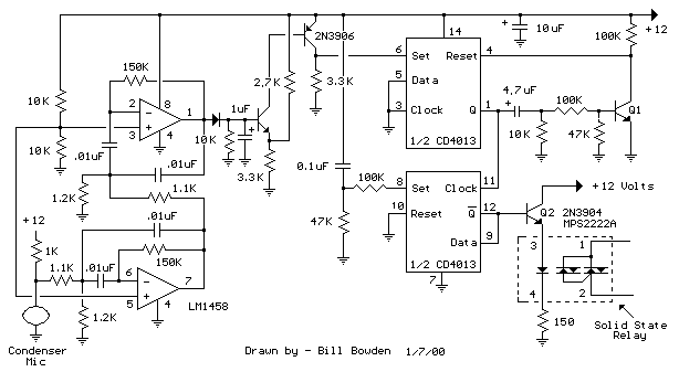
This is an extension of the CMOS toggle flip flop circuit shown in the Circuits controlling relays section with the addition of two bandpass filters and condenser microphone so the relay can be toggled by whistling at it. The condenser...
Chicken male and female discriminator 1
The male and female chicken discriminator circuit comprises an audio detection circuit, an active band-pass filter, and an LED display circuit, as illustrated in Figure 4-11. The audio detection circuit consists of a piezoelectric ceramic element (BC) and resistors R1...

sound sensor schematics
This is a simple sound sensor schematic that utilizes a single integrated circuit (IC) and two transistors to drive a relay. The schematic allows for sensitivity adjustment using a variable resistor (VR). This design is quite useful and can be...
home automation Installation
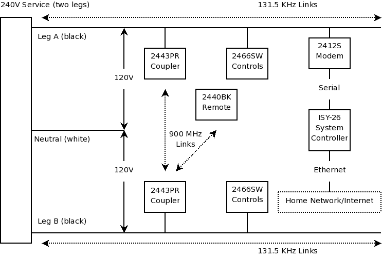
First and foremost, if one is not skilled with tools and electrical systems, it is advisable to hire a qualified electrician rather than attempting to undertake this task independently. The electrician should review this page for specific cautions and advice....