


ECG FM demodulator circuit diagram
#FM demodulator
#ECG
#medical data
#voltage controlled oscillator
#audio signal
#satellite transmission
#bandwidth
#frequency deviation
#receiver
#electronic systems
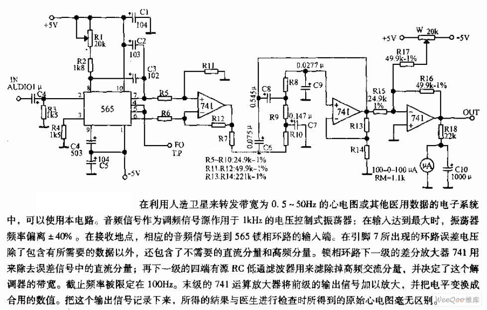
Description: The circuit is designed for satellite transmission of ECG signals with a bandwidth range of 0.5 to 50 Hz, as well as other medical data within electronic systems. An audio signal serves as the FM signal source, which is applied to a 1 kHz voltage-controlled oscillator. When the input signal reaches its maximum, the oscillator exhibits a frequency deviation of ± 40%. At the receiving end, the corresponding audio signal is transmitted.
The described circuit serves a critical role in the transmission of medical data, particularly ECG signals, over satellite communications. The bandwidth of 0.5 to 50 Hz is specifically chosen to accommodate the frequency characteristics of ECG signals, which are essential for monitoring heart activity. The use of an audio signal as the FM signal source allows for efficient modulation, utilizing frequency modulation techniques to encode the ECG data onto a carrier wave.
The voltage-controlled oscillator (VCO) operates at a nominal frequency of 1 kHz, which is suitable for the modulation of low-frequency medical signals. The VCO's ability to deviate by ± 40% from its center frequency ensures that the circuit can adapt to variations in the input signal amplitude, thereby maintaining signal integrity during transmission. This frequency deviation is crucial for accurately representing the ECG waveform and other medical data, ensuring that the information received is both reliable and precise.
At the receiving end of the system, the corresponding audio signal is demodulated to retrieve the transmitted ECG data. This process involves filtering and amplification stages to ensure that the received signal is clear and free from noise, which is vital in medical applications where data accuracy is paramount. The overall design emphasizes low power consumption and high fidelity, making it suitable for use in portable and remote medical monitoring systems.
In summary, this circuit is a sophisticated solution for satellite-based transmission of vital medical data, leveraging FM modulation techniques and robust signal processing to ensure accurate and reliable communication of ECG signals.The circuit is suitable for satellite to transmit the ECG with bandwidth in 0.5 ~ 50Hz or other medical data in electronic systems. Audio signal is used as FM signal source applied to the 1KHz voltage controlled oscillator: when the input is maximum, the oscillator frequency deviation is ± 40%.
In the receiving place, the corresponding audio signal is sent..
The described circuit serves a critical role in the transmission of medical data, particularly ECG signals, over satellite communications. The bandwidth of 0.5 to 50 Hz is specifically chosen to accommodate the frequency characteristics of ECG signals, which are essential for monitoring heart activity. The use of an audio signal as the FM signal source allows for efficient modulation, utilizing frequency modulation techniques to encode the ECG data onto a carrier wave.
The voltage-controlled oscillator (VCO) operates at a nominal frequency of 1 kHz, which is suitable for the modulation of low-frequency medical signals. The VCO's ability to deviate by ± 40% from its center frequency ensures that the circuit can adapt to variations in the input signal amplitude, thereby maintaining signal integrity during transmission. This frequency deviation is crucial for accurately representing the ECG waveform and other medical data, ensuring that the information received is both reliable and precise.
At the receiving end of the system, the corresponding audio signal is demodulated to retrieve the transmitted ECG data. This process involves filtering and amplification stages to ensure that the received signal is clear and free from noise, which is vital in medical applications where data accuracy is paramount. The overall design emphasizes low power consumption and high fidelity, making it suitable for use in portable and remote medical monitoring systems.
In summary, this circuit is a sophisticated solution for satellite-based transmission of vital medical data, leveraging FM modulation techniques and robust signal processing to ensure accurate and reliable communication of ECG signals.The circuit is suitable for satellite to transmit the ECG with bandwidth in 0.5 ~ 50Hz or other medical data in electronic systems. Audio signal is used as FM signal source applied to the 1KHz voltage controlled oscillator: when the input is maximum, the oscillator frequency deviation is ± 40%.
In the receiving place, the corresponding audio signal is sent..

Receiver monitor
The alarm connects to the earphone jack on a receiver. When a signal, typically sent to the headphones, is detected and applied to the gate of SCR1, it conducts, activating the alarm connected to SOI. The signaling device can be...

Differential super-regenerative self-limiting FM demodulator
The following is a translation of a section from the first book of the three-part series "Die Röhre im UKW Empfang" edited by Dr. Ing. Horst Rothe in 1952. This section describes a fully differential super-regenerative self-limiting FM detector. The...

41-72MHz micro-receiver ( MC3362 )
This receiver weighs about 6 g, used in 41 and 72 MHz, met a great success with readers of the magazine. The RX22 is the subject of these lines is improved RX20. Adding a preamp-HF improving sensitivity. Establishment of an...

REGENERATIVE_SHORTWAVE_RECEIVER
The receiver consists of multiple subassemblies, including an active antenna, an amplifier featuring regeneration control and band-switching circuitry, an AM detector, a power amplifier, and an output device such as an internal speaker, external speaker, or headphones. Additionally, it is...

Precision voltage controlled oscillator
The linearity of the input sweep voltage in relation to the output frequency is significantly enhanced by utilizing an operational amplifier.
The utilization of an operational amplifier (op-amp) in electronic circuits is a common practice to improve the linearity of input-output...
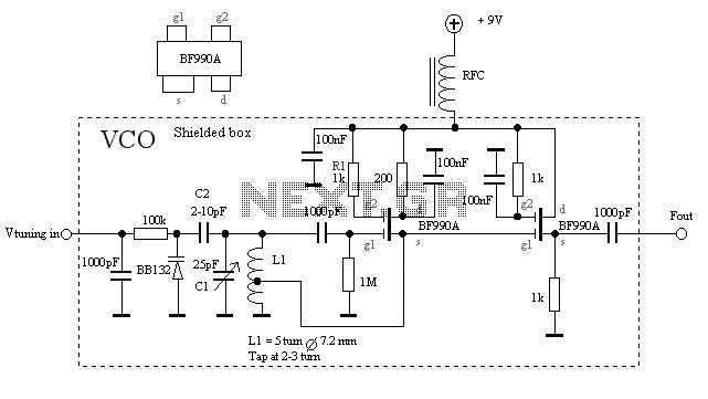
Voltage Controlled Oscillator with BF990A
The VCO is based on a Hartley oscillator. The frequency is determined by L1 and capacitor C1. The tuning voltage will change the capacitance in the varactor BB132 which will change the oscillation frequency. The value of capacitor C2 will...

Fm demodulator
The NE564 functions as an FM demodulator. The operational connections for both 5 V and 12 V configurations are illustrated in Figures 21-4A and 21-4B. The input signal is AC coupled, with the output signal extracted from Pin 14. Loop...

ECG telemetry circuit diagram
The circuit is designed for teaching demonstrations or experiments to hear the electrocardiogram (ECG) signal voltage. The ECG signal voltage is amplified by the LM4250 operational amplifier, which is connected to a voltage-controlled oscillator (NE566) to modulate the oscillator output....

FM demodulator circuit diagram 567
The FM demodulation circuit is illustrated in Figure 567. The FM signal is input at pin 3, and the demodulated signal is output from pin 5. The center frequency of the FM demodulation circuit is determined by the formula fo...