


GSM Phone Jammer Circuit Schematics
#GSM jammer
#NE555
#transistor oscillator
#800MHz-2GHz
#trim-capacitor
#frequency span
#signal blocking
#wireless interference
#RF circuit
#noise generation

Description: The circuit is based on the NE555 timer, functioning as a simple noise maker, with its output connected to a single transistor oscillator. This oscillator is designed to operate within a frequency range of 800 MHz to 2 GHz, which corresponds to the frequency range utilized by GSM phones. The operational frequency is adjustable using a trim capacitor.
The circuit is capable of transmitting signals up to a distance of 30 meters. It is recommended to modify the parameters of the circuit and to use a higher power supply for enhanced performance.
The NE555 timer is configured in astable mode, generating a square wave output that drives the base of a transistor, which in turn amplifies the signal. The transistor is chosen based on its frequency response and power handling capabilities to ensure efficient operation within the specified frequency range.
The oscillator's frequency is determined by the values of the resistors and the trim capacitor connected to the NE555. The trim capacitor allows for fine-tuning of the output frequency, enabling precise adjustments to align with the desired GSM frequency bands.
For optimal performance, the circuit should be powered by a stable power supply, preferably one that can provide a voltage higher than the standard operating range of the NE555, to ensure reliable oscillation and signal transmission. Additionally, careful consideration should be given to the layout of the circuit to minimize noise and interference, which can affect the oscillator's performance.
The design allows for a range of applications, including signal generation for communication systems, where the ability to transmit over distances of up to 30 meters can be advantageous. Proper shielding and antenna design may also be implemented to enhance the transmission range and signal clarity.It is based on NE555 as simple noise-maker whose output is fed to a single transistor oscillator. The oscillator is designed to operate between 800MHz and 2GHz which happens to be the frequency span used for GSM phones. The frequency of operation is set with a trim-capacitor. Ovaj bi do 30 metara, a ovaj drugi bi da mu neko javlja na mail. Ne budite lijeni i dokoni vec semu u ruke i konstruisite a ovom prvom preporucujem modifikaciju parametara seme i vece napajanje svakako.
The circuit is capable of transmitting signals up to a distance of 30 meters. It is recommended to modify the parameters of the circuit and to use a higher power supply for enhanced performance.
The NE555 timer is configured in astable mode, generating a square wave output that drives the base of a transistor, which in turn amplifies the signal. The transistor is chosen based on its frequency response and power handling capabilities to ensure efficient operation within the specified frequency range.
The oscillator's frequency is determined by the values of the resistors and the trim capacitor connected to the NE555. The trim capacitor allows for fine-tuning of the output frequency, enabling precise adjustments to align with the desired GSM frequency bands.
For optimal performance, the circuit should be powered by a stable power supply, preferably one that can provide a voltage higher than the standard operating range of the NE555, to ensure reliable oscillation and signal transmission. Additionally, careful consideration should be given to the layout of the circuit to minimize noise and interference, which can affect the oscillator's performance.
The design allows for a range of applications, including signal generation for communication systems, where the ability to transmit over distances of up to 30 meters can be advantageous. Proper shielding and antenna design may also be implemented to enhance the transmission range and signal clarity.It is based on NE555 as simple noise-maker whose output is fed to a single transistor oscillator. The oscillator is designed to operate between 800MHz and 2GHz which happens to be the frequency span used for GSM phones. The frequency of operation is set with a trim-capacitor. Ovaj bi do 30 metara, a ovaj drugi bi da mu neko javlja na mail. Ne budite lijeni i dokoni vec semu u ruke i konstruisite a ovom prvom preporucujem modifikaciju parametara seme i vece napajanje svakako.

Oscilloscope-calibrator
The calibrator can be utilized to verify the accuracy of a time-base generator and to calibrate the input level of amplifiers. It consists of an NE555 timer configured in astable mode. The oscillator frequency is precisely set to 1 kHz...

Radio Collar Transmitter Circuit using NE 555 IC
This is a radio transmitter circuit diagram designed for integration into radio collars using the NE 555 integrated circuit. The circuit transmits a pulse in the FM band, specifically between 88 MHz and 105 MHz.
The radio transmitter circuit utilizes the...
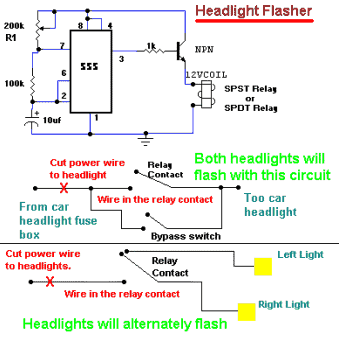
Headlight Flasher
A compact and intriguing circuit designed to flash automotive headlights. It utilizes a well-known NE555 timer circuit to achieve this functionality.
The circuit operates by employing the NE555 timer in astable mode, which allows it to generate a continuous square wave...

Assembly of the F&DARC Square Wave Generator/Bridge
This project integrates multiple features into a compact unit. The core driver is based on an NE555 square wave generator. During development, the idea of building a square wave generator using discrete components was considered, but experiments revealed that the...

NE555 triangular wave loading system, square wave generator circuit
The circuit depicted involves transistors VT1, VT2, and resistor R1, which form a constant current source for charging capacitor C2 in a linear manner. Transistors VT3, VT4, and resistor R2 create a constant current source for discharging capacitor C2, also...

on off relay circuit automatic
The circuit operates continuously, turning on and off. It utilizes the widely recognized NE555 timer IC, known for its versatility in various electronic applications. In this configuration, the IC is set up as an astable multivibrator. A 12-volt relay is...
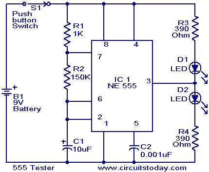
555 Tester circuit
The NE555 timer is configured as an astable multivibrator. When the push button switch S1 is pressed, the LEDs D1 and D2 will flash alternately. When the output is high, D2 will illuminate, and when the output is low, D1...

NE555 Timer
This article outlines the design and applications of the NE555 timer. The content is straightforward and informative, providing valuable insights into various components associated with the NE555. Readers can find and purchase these components through the article. It discusses several...

1kHz square wave signal generator
A 1 kHz square wave signal generator is created using a time base circuit with an NE555 timer, combined with a time constant circuit consisting of a 47 kΩ resistor and a 0.15 µF capacitor.
The circuit utilizes the NE555...