


Power pulse circuit by LM350 and NE555
#LM350
#NE555
#pulse generator
#power LED driver
#DC motor control
#adjustable output
#timer circuit
#voltage regulator

Description: Power pulse circuit using LM350 and NE555. This circuit can be used to drive lamps, power LEDs, DC motors, etc. Adjust R5 for output amplitude and R1 for output power. The LM350 is an adjustable 3-terminal voltage regulator.
The power pulse circuit utilizes the LM350 voltage regulator in conjunction with the NE555 timer IC, forming a versatile system capable of driving various loads such as lamps, LEDs, and DC motors. The LM350 serves as an adjustable voltage regulator, allowing for precise control over the output voltage and current, which is essential for applications where specific power levels are required.
The NE555 timer is configured in astable mode, generating a continuous square wave output. This square wave can be used to modulate the input to the LM350, effectively controlling the power delivered to the load. The frequency of the pulse can be adjusted by changing the resistor and capacitor values connected to the NE555, providing flexibility in operation.
R5 is a crucial resistor that controls the amplitude of the output pulse. By adjusting R5, the user can modify the peak voltage supplied to the load, ensuring that it operates within safe limits. This is particularly important when driving sensitive components like LEDs, which can be damaged by excessive voltage.
R1, on the other hand, adjusts the output power by influencing the voltage regulator's feedback loop. This adjustment allows for fine-tuning of the power supplied to the load, accommodating different load requirements and ensuring efficient operation.
The circuit design should include appropriate filtering capacitors at the output of the LM350 to stabilize the voltage and minimize ripple, especially when driving inductive loads such as motors, which can introduce noise and voltage spikes into the circuit. Additionally, proper heat sinking for the LM350 is recommended, as it may dissipate significant heat during operation, especially under high load conditions.
Overall, this power pulse circuit is a robust solution for various applications requiring controlled power delivery, with adjustable parameters to cater to different operational needs.Power pulse circuit by LM350 and NE555 . This circuit can use to drive lamp,power LED,DC motor etc. Adjust R5 for output amplitude.Adjust R1 for output power .The LM350 is adjustable 3-terminal.
The power pulse circuit utilizes the LM350 voltage regulator in conjunction with the NE555 timer IC, forming a versatile system capable of driving various loads such as lamps, LEDs, and DC motors. The LM350 serves as an adjustable voltage regulator, allowing for precise control over the output voltage and current, which is essential for applications where specific power levels are required.
The NE555 timer is configured in astable mode, generating a continuous square wave output. This square wave can be used to modulate the input to the LM350, effectively controlling the power delivered to the load. The frequency of the pulse can be adjusted by changing the resistor and capacitor values connected to the NE555, providing flexibility in operation.
R5 is a crucial resistor that controls the amplitude of the output pulse. By adjusting R5, the user can modify the peak voltage supplied to the load, ensuring that it operates within safe limits. This is particularly important when driving sensitive components like LEDs, which can be damaged by excessive voltage.
R1, on the other hand, adjusts the output power by influencing the voltage regulator's feedback loop. This adjustment allows for fine-tuning of the power supplied to the load, accommodating different load requirements and ensuring efficient operation.
The circuit design should include appropriate filtering capacitors at the output of the LM350 to stabilize the voltage and minimize ripple, especially when driving inductive loads such as motors, which can introduce noise and voltage spikes into the circuit. Additionally, proper heat sinking for the LM350 is recommended, as it may dissipate significant heat during operation, especially under high load conditions.
Overall, this power pulse circuit is a robust solution for various applications requiring controlled power delivery, with adjustable parameters to cater to different operational needs.Power pulse circuit by LM350 and NE555 . This circuit can use to drive lamp,power LED,DC motor etc. Adjust R5 for output amplitude.Adjust R1 for output power .The LM350 is adjustable 3-terminal.

Expand integrated three-terminal regulator block circuit output current method
Expand integrated three-terminal regulator block circuit output current method
The integrated three-terminal regulator is a versatile component commonly used in power supply circuits to provide a stable output voltage. This regulator typically consists of three terminals: input, output, and ground. The...

Adjustable output voltage power supply circuit MAX610
The output voltage can be calculated as follows: U = 1.3 (1 + R3 / R4) (V), where R3 and R4 are part of an adjustment potentiometer, allowing for a continuously adjustable output voltage.
The described circuit involves a voltage output...

The NE 555 Timer IC Datasheet Applications and Circuit Schematics
The sections available in this datasheet cover general design considerations for the 555 timer, frequently asked application questions (FAQ), design formulas, and examples of innovative applications. Examples of applications include a Missing Pulse Detector, Pulse Width Modulation (PWM), Tone Burst...

Clap Switch Circuit using NE555 timer IC
This is an intriguing 555 timer circuit designed to entertain and engage individuals while studying electronics in educational settings. Commonly referred to as a clap switch circuit, it operates as a sound-controlled flip-flop. This sound-controlled light can also function as...

Fully Automatic Emergency Light circuit
The circuit consists of inverter and charger sections. The inverter section utilizes the NE555 timer, while the charger section is based on the LM317 adjustable regulator. In the inverter section, the NE555 is configured as an astable multivibrator, generating a...

A thirty light water digital control circuit
The circuit consists of an oscillator, a counter, and an Iseki circuit divided into three parts. The oscillator is based on the NE555 timer and several external RC components, generating a pulse signal for the counter. The instantaneous power is...

Photo Switch Circuit
A simple photo switch circuit using the NE555 IC with a diagram and schematic. This photo switch activates a relay when light intensity exceeds a certain threshold. It serves as a light sensor circuit suitable for both home and industrial...

NE555 Basic Monostable
Here the popular 555 timing IC is wired as a monostable. The timing period is precise and equivalent to: 1.1 x R1 x C1. With component values shown this works out at approximately 1.1 msec. The output duration is independent...
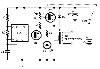
Muscular Bio-Stimulator
IC1 generates 150 µSec pulses at approximately 80Hz frequency. Q1 functions as a buffer, while Q2 inverts the pulse polarity and drives the transformer. The output pulse amplitude is adjusted by P1 and is visually indicated by the brightness of...