


Stun Gun with 555
#stun gun
#555 timer
#high voltage
#transformer
#9V battery
#pulse generator
#variable resistor
#shock circuit
#safety warning

Description: This stun gun is powered by a 9V battery. The transformer steps up the voltage to about 1800V (but with very low current). A 555 timer IC is used to generate a high-frequency output. A 1 MEG variable resistor can also be used at the output to drop the voltage, but this is optional. If you build this circuit, be careful, as it outputs a high voltage. Touching the output leads will induce a painful shock.
The circuit operates on a 9V battery, which serves as the primary power source. The 555 timer integrated circuit (IC) is configured in astable mode to produce a square wave signal at a high frequency, typically in the range of several kilohertz. This high-frequency output is essential for driving the transformer effectively, allowing it to step up the voltage.
The transformer utilized in this circuit is a high-voltage transformer designed to increase the voltage from the 9V input to approximately 1800V. It is crucial to note that while the voltage is significantly high, the output current remains low, which is a characteristic feature of stun gun circuits. This combination of high voltage and low current is what allows the device to deliver a painful shock without causing fatal harm.
In addition to the transformer, a 1 MEGΩ variable resistor can be integrated into the circuit at the output. This component serves as a means to adjust the output voltage, providing the user with the ability to control the intensity of the shock. However, the inclusion of this resistor is optional and may be omitted depending on the design preferences of the builder.
Safety precautions are paramount when constructing or handling this circuit. The high voltage output can induce a painful shock if contact is made with the output leads. Proper insulation and safety measures should be implemented to prevent accidental contact with the high-voltage components. It is recommended that individuals with adequate knowledge of high-voltage electronics should undertake the construction and testing of this stun gun circuit.This stun gun is powered by a 9V battery. The transformer steps up the voltage to about 1800V (but with very low current). A 555 timer IC is used to generate a high-frequency output. A 1 MEG variable resistor can also be used at the output to drop the voltage, but this is optional. If you build this circuit, be careful, as it outputs a high voltage. Touching the output leads will induce a painful shock.
The circuit operates on a 9V battery, which serves as the primary power source. The 555 timer integrated circuit (IC) is configured in astable mode to produce a square wave signal at a high frequency, typically in the range of several kilohertz. This high-frequency output is essential for driving the transformer effectively, allowing it to step up the voltage.
The transformer utilized in this circuit is a high-voltage transformer designed to increase the voltage from the 9V input to approximately 1800V. It is crucial to note that while the voltage is significantly high, the output current remains low, which is a characteristic feature of stun gun circuits. This combination of high voltage and low current is what allows the device to deliver a painful shock without causing fatal harm.
In addition to the transformer, a 1 MEGΩ variable resistor can be integrated into the circuit at the output. This component serves as a means to adjust the output voltage, providing the user with the ability to control the intensity of the shock. However, the inclusion of this resistor is optional and may be omitted depending on the design preferences of the builder.
Safety precautions are paramount when constructing or handling this circuit. The high voltage output can induce a painful shock if contact is made with the output leads. Proper insulation and safety measures should be implemented to prevent accidental contact with the high-voltage components. It is recommended that individuals with adequate knowledge of high-voltage electronics should undertake the construction and testing of this stun gun circuit.This stun gun is powered by a 9V battery. The transformer steps up the voltage to about 1800V (but with very low current). A 555 timer IC is used to generate a high-frequency output. A 1 MEG variable resistor can also be used at the output to drop the voltage, but this is optional. If you build this circuit, be careful, as it outputs a high voltage. Touching the output leads will induce a painful shock.
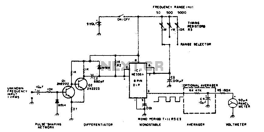
Linear frequency meter
The 555 timer is utilized in a monostable multivibrator circuit that generates a pulse of fixed time width, which is activated by an unknown input frequency.
The 555 timer in a monostable configuration operates by producing a single output pulse in...

The Simplest Car Battery Charger
This very simple circuit uses a transformer, two diodes, a capacitor, and an ammeter. To charge a battery, just connect the + and - terminals of the circuit to the corresponding terminals of the battery. When the battery is not...
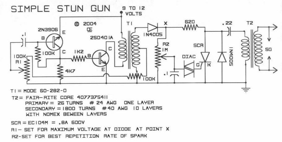
DIY Stun Gun Circuit
This is a DIY simple stun gun circuit presented solely for educational purposes. There is no recommendation for constructing these stun guns or for their actual use in any capacity.
The circuit for a DIY stun gun typically consists of a...

555 DC Voltage Doubler Circuit
This DC voltage doubler circuit generates a voltage that is double its supply voltage. It is advantageous when a higher voltage level is required from a single lower voltage power supply. Due to the low current consumption in such applications,...

Metal detector with 555 timer
This metal detector electronic project schematic circuit is designed using a simple 555 timer integrated circuit. The schematic circuit requires few external electronic components.
The metal detector circuit utilizes the 555 timer IC in an astable mode configuration, which generates a...

Variable speed electric motor bike circuit
The adjustment potentiometer (RP) allows for modification of the duty cycle of a square wave generated by the 555 integrated circuit (IC) in New Zealand, enabling control of motor speed within a range of 0 to 100%.
The circuit utilizes a...

please 555 circuit
The individual expressed frustration while attempting to connect a circuit to a 15V supply, bypassing resistor R3 with a clip-on soldering heat sink. They noted that 555 timers emit a distinct odor when damaged. They have limited components remaining and...

High voltage (120V), converting familiar fast (120V Shu us) power MOSFET Amplifier circuit
The south circuit consists of four parts, arranged in descending order: an NPN transistor dynamic garbage device (T1), a PNP transistor differential amplifier (T2, T3) forming a double differential circuit, two balanced output amplifiers with opposite phase, and a voltage...

Electronic Dice circuit
The IC1 is a 555 timer IC configured for astable operation, generating clock pulses that are fed to IC2 through a 10K resistor. IC2 is a 10-stage counter, with output 6 (pin 5) connected to RESET (pin 15), resulting in...