


2.4G wireless keyboard receiver part of the circuit

Description: The circuit diagram for the receiving portion of a 2.4 GHz wireless keyboard is presented below.
The 2.4 GHz wireless keyboard receiving circuit typically consists of several key components that work together to receive and process signals transmitted from the keyboard. The main components include an antenna, a radio frequency (RF) receiver module, a microcontroller, and associated passive components such as resistors and capacitors.
The antenna is responsible for capturing the RF signals transmitted by the wireless keyboard. It is designed to operate efficiently at 2.4 GHz, ensuring optimal reception of the signals. The RF receiver module demodulates the incoming signals, converting them from radio frequency to baseband signals that can be processed by the microcontroller.
The microcontroller serves as the central processing unit of the receiving circuit. It interprets the demodulated signals, translating them into commands that correspond to keystrokes made on the keyboard. The microcontroller may also include firmware that manages the communication protocol and handles any error correction necessary for reliable data transmission.
Additionally, passive components such as capacitors and resistors are used to filter noise and stabilize the power supply to the RF receiver and microcontroller. Proper design of the power supply circuit is crucial to ensure that the components operate within their specified voltage and current ranges, thereby enhancing the overall performance and reliability of the wireless keyboard system.
In summary, the 2.4 GHz wireless keyboard receiving circuit integrates an antenna, RF receiver, microcontroller, and passive components to effectively receive and process wireless signals, enabling seamless communication between the keyboard and the host device. This design is essential for achieving the desired user experience in wireless keyboard applications.2.4G wireless keyboard receiving portion circuit diagram as follows:
The 2.4 GHz wireless keyboard receiving circuit typically consists of several key components that work together to receive and process signals transmitted from the keyboard. The main components include an antenna, a radio frequency (RF) receiver module, a microcontroller, and associated passive components such as resistors and capacitors.
The antenna is responsible for capturing the RF signals transmitted by the wireless keyboard. It is designed to operate efficiently at 2.4 GHz, ensuring optimal reception of the signals. The RF receiver module demodulates the incoming signals, converting them from radio frequency to baseband signals that can be processed by the microcontroller.
The microcontroller serves as the central processing unit of the receiving circuit. It interprets the demodulated signals, translating them into commands that correspond to keystrokes made on the keyboard. The microcontroller may also include firmware that manages the communication protocol and handles any error correction necessary for reliable data transmission.
Additionally, passive components such as capacitors and resistors are used to filter noise and stabilize the power supply to the RF receiver and microcontroller. Proper design of the power supply circuit is crucial to ensure that the components operate within their specified voltage and current ranges, thereby enhancing the overall performance and reliability of the wireless keyboard system.
In summary, the 2.4 GHz wireless keyboard receiving circuit integrates an antenna, RF receiver, microcontroller, and passive components to effectively receive and process wireless signals, enabling seamless communication between the keyboard and the host device. This design is essential for achieving the desired user experience in wireless keyboard applications.2.4G wireless keyboard receiving portion circuit diagram as follows:

Usb Power Socket With Indicator circuit
Today, nearly all computers are equipped with logic blocks designed to implement a USB port. In practice, a USB port can deliver over 100 mA of continuous current at 5V to the peripherals connected to the bus. This capability allows...

Rf-Type Battery Charger Circuit
This type of charger transfers RF energy from an inductor (L2) to an external pickup coil. The pickup coil is connected to a rectifier and a battery that requires charging. This design is advantageous as it eliminates the need for...
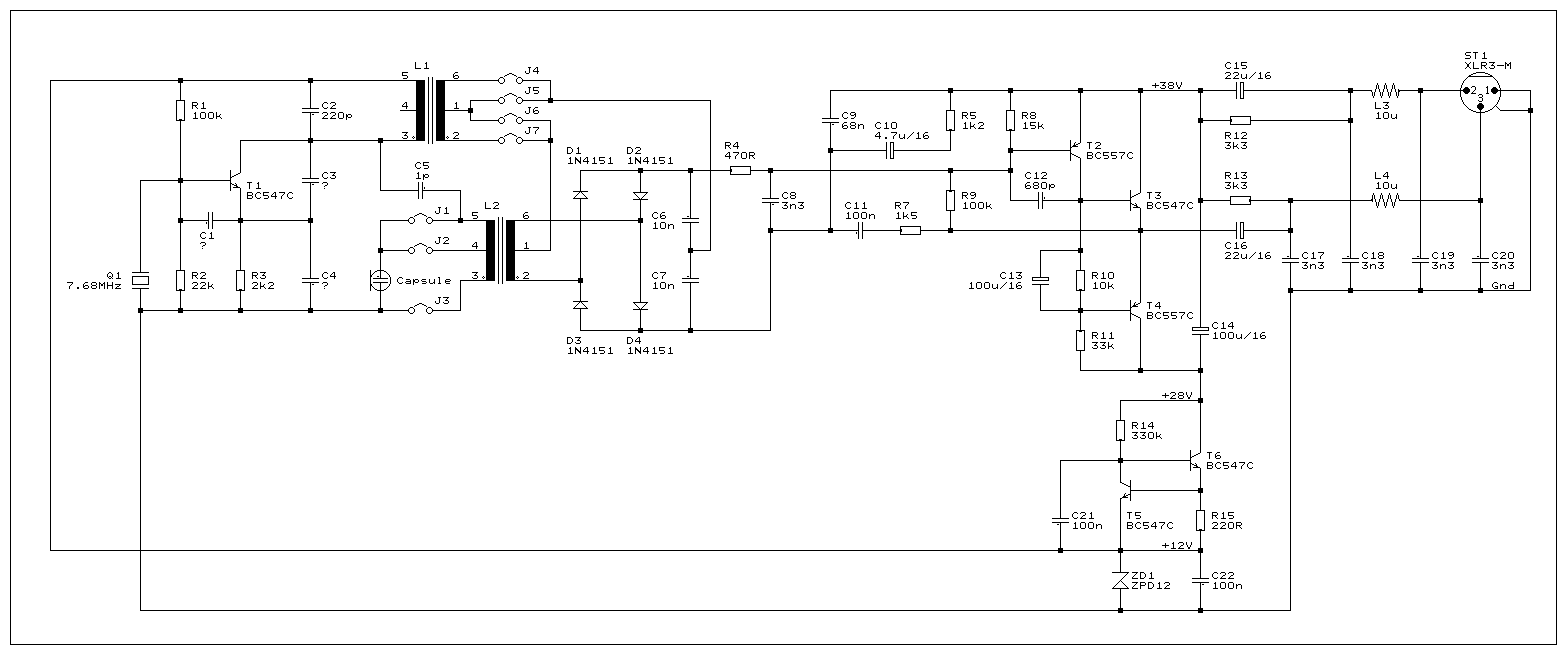
HF Mic
This RF circuit operates at 7.68 MHz and is supplied with 48V phantom power. It has been tested with a large diaphragm cardioid capsule designed by Ralf Falk, who is also known for creating a LF tube microphone, and with...

80M And 40M Cw-Ssb Receiver Circuit
This direct-conversion receiver utilizes a TDA7000 integrated circuit (IC) and incorporates an LM386 audio amplifier. The TDA7000 serves as the mixer and local oscillator (L.O.) section. The frequency control can be achieved using either an air variable capacitor or a...

calradio
Cal-(IT)2 is developing several generations of general broad application radio/networking test platforms for wireless research and development. CalRadio I is the first generation. It provides a simple, low-cost platform for 802.11b development from the MAC layer and up. It accomplishes...

USB DC Power Supply from Cigar Lighter Socket
The diagram illustrates the circuit of a versatile USB power socket that safely converts 12V battery voltage into a stable 5V output. This circuit enables the use of various USB-powered devices.
The circuit design consists of several key components to ensure...
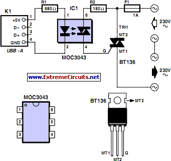
USB Operated Home Appliances
When powering a computer on and off, various peripherals, including printers, screens, scanners, and others, often need to be activated or deactivated simultaneously. By implementing a system that manages these peripherals...
In modern computing environments, managing the power states of peripherals...
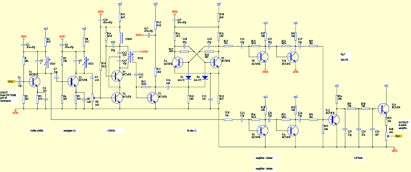
Amatorki projekt
The circuit is designed to add two identical branches to the existing despreading spectrum. The only difference between the branches is the phase of the PN sequences fed into each branch, specifically at the input of a double-balanced mixer. The...

usb pow
The USB standard limits the current consumption of all USB devices to either 100mA or 500mA, depending on the specifications of the USB hub or host controller (e.g., a computer) supplying the power. Ideally, no USB device should draw more...