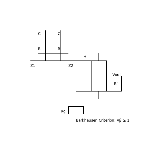
RC Phase Shift Oscillators
1. Basic Principle of Phase Shift Oscillation
1.1 Basic Principle of Phase Shift Oscillation
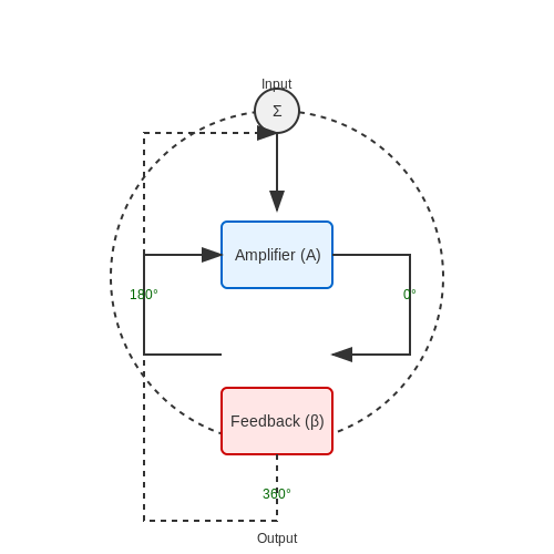
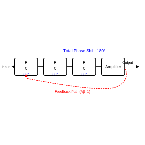
An RC phase shift oscillator generates sinusoidal oscillations by leveraging a feedback network that introduces a total phase shift of 180° at a specific frequency, which, when combined with the inherent 180° phase inversion of an amplifier, satisfies the Barkhausen criterion for sustained oscillations. The core mechanism relies on cascaded RC networks, each contributing a portion of the total phase shift, while the amplifier compensates for signal attenuation.
Phase Shift Network Analysis
The phase shift network typically consists of three or four cascaded RC sections (high-pass filters). Each RC section provides a phase shift φ given by:
For three identical RC sections, the total phase shift φtotal must reach 180° at the oscillation frequency fosc. Solving the phase condition:
yields the oscillation frequency:
Barkhausen Criterion
The oscillator must satisfy two conditions:
- Loop gain condition: The amplifier's gain A must offset the attenuation of the RC network. For a three-stage network, the attenuation β is 1/29, requiring A ≥ 29.
- Phase condition: Total loop phase shift must be 0° or 360° (including amplifier inversion).
Amplifier Requirements
A transistor or op-amp in common-emitter/inverting configuration provides the necessary 180° phase inversion. The gain must be stabilized at 29 via negative feedback (e.g., emitter resistor or op-amp gain control) to avoid waveform distortion.
Practical Design Considerations
Component tolerances directly impact frequency stability. Temperature coefficients of resistors and capacitors introduce drift, necessitating precision components for applications like audio signal generation or frequency references. Non-ideal op-amp characteristics (slew rate, bandwidth) may limit high-frequency performance.
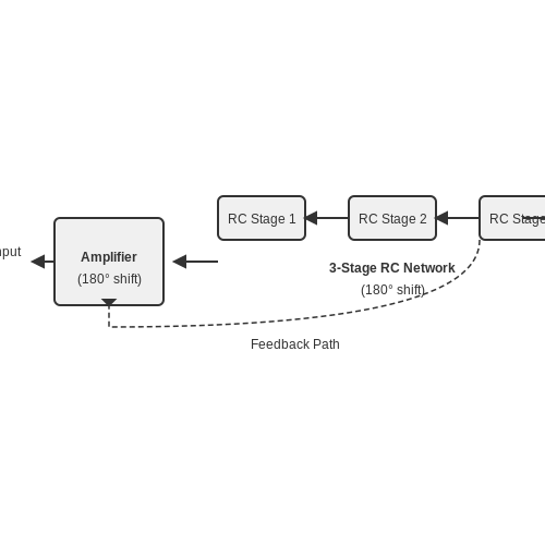
Role of RC Networks in Phase Shifting
Fundamental Operation of RC Networks
An RC network consists of a resistor (R) and a capacitor (C) connected in series or parallel. When an AC signal passes through such a network, the voltage and current become phase-shifted due to the reactive nature of the capacitor. The phase shift (φ) introduced by a single RC section is given by:
where XC = 1/(ωC) is the capacitive reactance and ω is the angular frequency. For a high-pass RC network, the output leads the input, while for a low-pass configuration, the output lags.
Cascaded RC Networks for Larger Phase Shifts
A single RC section provides a phase shift of up to 90°, but practical oscillators often require 180° for sustained oscillations. By cascading multiple RC sections, the cumulative phase shift increases. For n identical RC sections, the total phase shift is:
In RC phase shift oscillators, three sections are typically used to achieve the necessary 180° phase shift at the oscillation frequency. The transfer function of each section attenuates the signal, requiring amplification to sustain oscillations.
Frequency-Dependent Behavior
The phase shift is frequency-dependent, meaning the oscillator will only sustain oscillations at the frequency where the total phase shift equals 180°. The oscillation frequency (fosc) for a three-section RC network is derived from the Barkhausen criterion:
This relationship assumes identical R and C values across all sections. Deviations in component tolerances can affect frequency stability and harmonic distortion.
Practical Considerations
In real-world implementations, non-ideal effects such as parasitic capacitances, resistor tolerances, and op-amp bandwidth limitations influence performance. Stray capacitances can unintentionally alter the phase shift, while finite amplifier gain impacts loop gain conditions. To mitigate these issues, precision components and temperature-stable materials (e.g., NP0 capacitors, metal-film resistors) are preferred.
Applications in Oscillator Design
RC phase shift networks are foundational in audio-frequency oscillators, where their simplicity and tunability make them ideal for sine wave generation. They are also used in phase-sensitive detection circuits and feedback control systems. Modern variants employ programmable resistors or switched capacitors for frequency agility in software-defined radio and test equipment.
1.3 Conditions for Sustained Oscillation
For an RC phase shift oscillator to maintain stable oscillations, two fundamental conditions must be satisfied: the Barkhausen criteria. These criteria ensure that the feedback loop sustains oscillations at a desired frequency without damping or uncontrolled growth.
Barkhausen Criterion: Loop Gain
The first condition requires the loop gain Aβ to be unity at the oscillation frequency f0:
Here, A represents the amplifier gain, and β is the feedback network's transfer function. If |Aβ| < 1, oscillations decay; if |Aβ| > 1, the amplitude grows until nonlinearities limit it.
Barkhausen Criterion: Phase Shift
The second condition mandates a total phase shift of 0° or 360° around the loop:
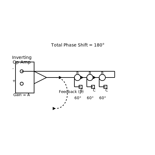
In an RC phase shift oscillator, the amplifier (typically an inverting op-amp) contributes 180°, and the RC network must provide an additional 180° at f0.
Derivation of Oscillation Frequency
For a three-stage RC network, each RC section introduces a phase shift θ. The total phase shift is:
The phase shift of a single RC high-pass section is:
Setting θ = 60° and solving for ω:
Minimum Amplifier Gain
To satisfy |Aβ| = 1, the amplifier gain A must compensate for the RC network's attenuation. For a three-stage RC network, the attenuation β at f0 is:
Thus, the amplifier gain must be:
In practice, a gain slightly larger than 29 ensures reliable startup, with amplitude stabilization achieved through amplifier nonlinearities or automatic gain control (AGC).
Practical Considerations
- Component Tolerances: Variations in R and C values affect f0 and may require trimming.
- Amplifier Bandwidth: The op-amp must have sufficient bandwidth to avoid additional phase shifts at f0.
- Thermal Stability: Temperature-dependent component drifts can destabilize oscillations.
Modern designs often use programmable resistors or digital tuning to maintain precision in variable-frequency applications.
2. Components and Their Functions
2.1 Components and Their Functions
Core Components of an RC Phase Shift Oscillator
An RC phase shift oscillator relies on three primary components to generate sustained sinusoidal oscillations: resistors (R), capacitors (C), and an amplifying device (typically a transistor or op-amp). The phase-shifting network, composed of cascaded RC sections, provides the necessary 180° phase shift at the oscillation frequency, while the amplifier introduces an additional 180° shift to satisfy the Barkhausen criterion.
Resistors and Capacitors in the Phase-Shift Network
The phase-shift network consists of three identical RC sections, each contributing approximately 60° of phase shift at the oscillation frequency. The values of R and C determine the frequency of oscillation, derived as:
The resistors must be precision-matched to ensure uniform phase shift across each section. Capacitors are typically polypropylene or ceramic for stability, with tolerances ≤5% to minimize frequency drift.
Amplifying Device: Transistor vs. Op-Amp
The amplifier compensates for energy losses in the passive network. Two common implementations exist:
- BJT-Based Design: A common-emitter transistor provides high gain (>29) and the required phase inversion. The bias network (R1, R2, RE, CE) must stabilize the Q-point against temperature variations.
- Op-Amp Design: An inverting op-amp configuration offers superior gain control and distortion characteristics. The gain must satisfy Av ≥ 29 to overcome attenuation in the RC network.
Feedback Mechanism and Gain Requirements
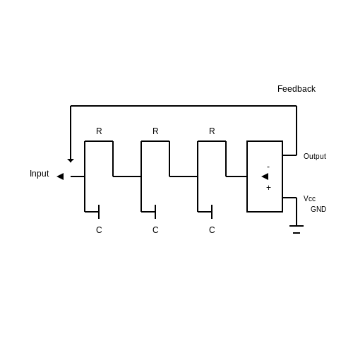
The feedback loop transfers the output signal back through the phase-shift network. For oscillations to sustain, the loop gain must satisfy:
where β is the attenuation of the RC network (1/29 at oscillation frequency) and Av is the amplifier gain. Practical designs incorporate automatic gain control (AGC) or nonlinear elements (e.g., diodes) to limit amplitude growth.
Power Supply Considerations
A regulated DC supply is critical for frequency stability. Voltage fluctuations alter transistor parameters or op-amp bias points, introducing phase noise. For high-precision applications, supply ripple should be kept below 10 mVp-p using LC filtering or low-noise LDO regulators.
Practical Component Selection Guidelines
- Resistors: Metal-film types (e.g., 1% tolerance) minimize thermal noise and drift. Values typically range from 1 kΩ to 100 kΩ for compatibility with standard op-amp outputs.
- Capacitors: NP0/C0G ceramics or film capacitors (1 nF–100 nF) provide stable capacitance vs. temperature and voltage.
- Amplifier: Choose devices with gain-bandwidth product (GBW) ≥10× the oscillation frequency to avoid phase errors. For MHz-range oscillators, high-speed op-amps like the AD811 are preferred.
2.2 Frequency Determination and Feedback Mechanism
Frequency of Oscillation
The oscillation frequency of an RC phase shift oscillator is determined by the phase shift network, typically consisting of three cascaded RC sections. For sustained oscillations, the total phase shift must be 180°, with each RC section contributing approximately 60° at the desired frequency. The frequency f is derived from the transfer function of the network.
This equation arises from solving the Barkhausen criterion for the three-stage RC network, where the imaginary part of the denominator in the loop gain equation must cancel out at the oscillation frequency. The derivation begins with the impedance of each RC section:
For three identical sections, the transfer function β of the feedback network is:
Applying the Barkhausen criterion (|Aβ| = 1 and phase shift of 180°), the oscillation frequency simplifies to the earlier result. Practical implementations often use slightly adjusted component values to account for non-ideal op-amp characteristics or transistor parasitics.
Feedback Mechanism and Gain Requirements
The amplifier in an RC phase shift oscillator must provide sufficient gain to compensate for the attenuation of the feedback network. For a three-stage RC network, the attenuation factor β at the oscillation frequency is:
Thus, the amplifier gain A must satisfy:
In transistor-based designs, this is achieved through common-emitter stages, while op-amp implementations use non-inverting configurations. Stability analysis reveals that exceeding the minimum gain marginally improves startup reliability but risks waveform distortion due to overdriving.
Practical Considerations
Component tolerances directly impact frequency stability. A 1% variation in R or C introduces a 0.5% frequency shift. Temperature coefficients of resistors and capacitors must be matched in precision applications. For example, using NPO capacitors with metal-film resistors maintains stability within 100 ppm/°C.
In real-world designs, a nonlinear element (e.g., a JFET or incandescent lamp) is often incorporated to automatically regulate gain and stabilize amplitude. This compensates for supply voltage fluctuations and component aging.
Historical Context
The RC phase shift oscillator was among the first electronic oscillator topologies, dating back to early 20th-century vacuum tube designs. Its simplicity made it a cornerstone in analog signal generation for applications ranging from audio testing to carrier wave synthesis in vintage radio transmitters.
Modern Applications
Contemporary uses include low-cost function generators and clock sources for embedded systems where quartz stability is unnecessary. Recent research explores CMOS implementations with on-chip RC networks for IoT devices, achieving 0.1% frequency accuracy at 1 MHz with auto-calibration algorithms.
2.3 Gain Requirements for Oscillation
For an RC phase shift oscillator to sustain oscillations, the amplifier must provide sufficient gain to compensate for the energy losses in the feedback network. The Barkhausen criterion states that the loop gain must satisfy two conditions:
- The magnitude of the loop gain must be unity (|Aβ| = 1).
- The total phase shift around the loop must be an integer multiple of 360° (0° or ±360°).
Derivation of Minimum Gain
In an RC phase shift oscillator, the feedback network consists of three cascaded RC sections, each contributing approximately 60° of phase shift at the oscillation frequency. The total phase shift is thus 180°, and the amplifier must introduce an additional 180° phase shift (inverting amplifier) to meet the Barkhausen phase condition.
The transfer function of the three-section RC network is:
At the oscillation frequency (f0), the phase shift is 180°, meaning the imaginary part of the denominator must be zero. Solving for ω0:
The magnitude of the feedback factor at ω0 is:
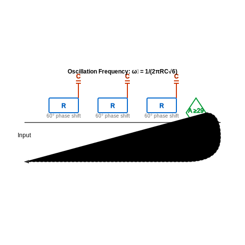
To satisfy |Aβ| = 1, the amplifier gain A must be at least 29. In practice, a slightly higher gain (e.g., 30–35) is used to ensure reliable startup.
Practical Considerations
Real-world implementations must account for component tolerances, temperature variations, and nonlinearities. Key design considerations include:
- Amplifier selection: Op-amps or transistor-based amplifiers must have sufficient bandwidth and slew rate to avoid distortion.
- Nonlinear limiting: Automatic gain control (AGC) or soft clipping ensures stable amplitude without excessive harmonic distortion.
- Component precision: Tight-tolerance resistors and capacitors minimize frequency drift.
Stability Analysis
Small-signal stability can be analyzed using the Nyquist criterion. The loop gain Aβ must encircle the point (-1, 0) in the complex plane exactly once. Excessive gain can lead to multiple encirclements, causing instability or saturation.
where ωc is the crossover frequency where |Aβ| = 1. A phase margin > 45° is typically desired for robust oscillation.
Design Example
For a 1 kHz oscillator with R = 10 kΩ and C = 10 nF:
The required amplifier gain is:
A non-inverting op-amp configuration with R1 = 1 kΩ and R2 = 28 kΩ yields a gain of 29, satisfying the condition.
3. Common Circuit Configurations
3.1 Common Circuit Configurations
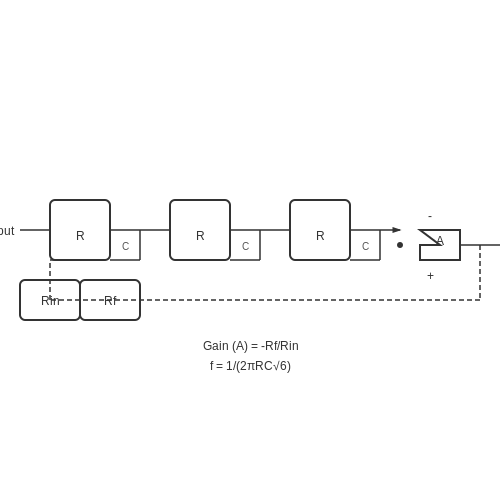
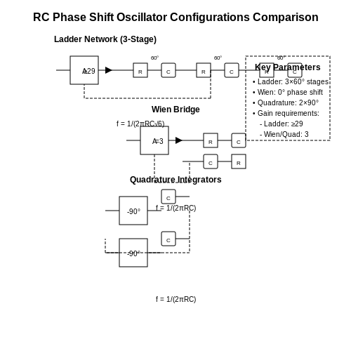
The RC phase shift oscillator achieves sustained oscillations through a combination of an inverting amplifier and a frequency-selective RC feedback network. The most prevalent configurations include the three-stage RC ladder network and the Wien bridge variant, each offering distinct trade-offs in frequency stability, harmonic distortion, and tuning range.
Three-Stage RC Ladder Network
This topology employs three cascaded RC high-pass filters, each contributing approximately 60° of phase shift at the oscillation frequency. The total phase shift of 180°, combined with the amplifier's inherent 180° inversion, satisfies the Barkhausen criterion for positive feedback. The oscillation frequency f is derived from the network's transfer function:
The amplifier gain must precisely compensate for the attenuation of the RC network, requiring:
Practical implementations often use a BJT or op-amp with negative feedback resistors to stabilize the gain. Component tolerance directly impacts frequency accuracy—metal film resistors and polystyrene capacitors are preferred for stability.
Wien Bridge Configuration
While not strictly an RC phase shift oscillator, the Wien bridge variant merits discussion due to its superior frequency stability. It uses a series-parallel RC network producing zero phase shift at resonance:
The amplifier must provide a non-inverting gain of exactly 3, typically implemented with a thermistor or JFET-based automatic gain control to limit distortion. This configuration exhibits lower harmonic distortion than the ladder network but requires tighter component matching.
Quadrature Oscillator Variant
A less common but mathematically elegant approach uses two integrators in a loop, generating sine and cosine outputs simultaneously. The oscillation frequency remains:
This configuration finds niche applications in communication systems where phase-coherent signals are required. However, it demands precisely matched time constants in both integrators to maintain amplitude balance.
Practical Design Considerations
- Amplifier bandwidth must significantly exceed the oscillation frequency to avoid parasitic phase shifts
- Capacitor dielectric absorption introduces nonlinearities—polypropylene or NP0 ceramics are optimal
- Thermal drift in resistors can cause frequency instability; temperature-compensated networks may be necessary for precision applications
3.2 Component Selection and Tuning
Resistor and Capacitor Selection Criteria
The oscillation frequency of an RC phase shift oscillator is determined by the values of the resistors (R) and capacitors (C) in the feedback network. For a three-stage RC network, the oscillation frequency \( f \) is given by:
To ensure stable oscillations, the gain of the amplifier must satisfy the Barkhausen criterion, requiring a minimum gain of 29. This imposes constraints on component selection:
- Resistor tolerance: Use resistors with ≤1% tolerance to minimize frequency drift due to manufacturing variations.
- Capacitor type: Polypropylene or NP0/C0G ceramic capacitors are preferred for their low temperature coefficients (≤30 ppm/°C).
- Parasitic effects: At high frequencies (>100 kHz), stray capacitance and lead inductance become significant, necessitating surface-mount components.
Gain Adjustment and Stability
The amplifier gain \( A_v \) must be precisely set to compensate for losses in the RC network. For a standard inverting op-amp configuration:
where \( R_f \) is the feedback resistor and \( R_{in} \) is the input resistor. To achieve the required gain of 29:
- Start with \( R_f = 29 \times R_{in} \), then fine-tune using a potentiometer to account for component tolerances.
- Include a negative temperature coefficient (NTC) thermistor in series with \( R_f \) to compensate for thermal drift in the RC network.
Practical Tuning Techniques
Laboratory tuning involves iterative adjustments:
- Measure the output frequency with a frequency counter.
- Adjust one capacitor (C) while keeping others fixed to minimize harmonic distortion.
- Use a spectrum analyzer to verify the absence of spurious modes.
For voltage-controlled oscillation, replace fixed resistors with JFETs or varactor diodes, where the effective resistance is given by:
Component Matching and Thermal Considerations
Mismatched RC sections introduce phase errors, leading to frequency instability. To mitigate this:
- Select components from the same manufacturing batch to ensure consistent parameters.
- Implement symmetrical PCB layout to equalize parasitic capacitances.
- Use temperature-compensated voltage references (e.g., LM335) if the oscillator operates in varying thermal environments.
3.3 Troubleshooting Common Issues
Oscillation Failure
If the oscillator fails to start, verify the Barkhausen criterion: the loop gain must satisfy |Aβ| ≥ 1 at the phase shift frequency (180°). Common causes include:
- Insufficient gain: The amplifier's open-loop gain (A) must compensate for the RC network's attenuation (1/29 for a 3-stage oscillator).
- Component tolerance errors: Resistor/capacitor mismatches alter the phase shift network's transfer function.
- Bias point instability: Active devices (BJTs/FETs) may operate outside the linear region due to improper DC biasing.
Frequency Instability
Observed frequency drift often stems from:
- Temperature-dependent components: Capacitors with high temperature coefficients (e.g., ceramic discs) cause df/dT shifts.
- Power supply ripple: Non-regulated supplies modulate the active device's transconductance (gm), inducing jitter.
- Parasitic capacitances: Stray PCB capacitances (Cp) parallel to RC elements modify the phase shift condition.
Distorted Output Waveform
Non-sinusoidal outputs indicate nonlinear operation:
- Overdriven amplifier: Clipping occurs when loop gain significantly exceeds unity. Introduce automatic gain control (AGC) or reduce feedback.
- Harmonic generation: High-Q networks (Q > 1) may sustain multiple frequencies. Add a bandpass filter at fosc.
- Ground loops: Improper grounding creates common-mode interference. Use star grounding for critical nodes.
Start-Up Time Variability
Excessive delay before oscillation onset suggests:
- Noise floor limitations: Low thermal noise in high-impedance designs requires higher initial perturbations.
- Leaky capacitors: Dielectric absorption in electrolytics delays voltage buildup across phase-shift stages.
- Non-optimal biasing: Class-C biased amplifiers exhibit longer transient responses than Class-A.
Diagnostic Procedure
- Measure DC operating points with an oscilloscope (coupling set to DC).
- Inject a swept sine wave (20Hz–20kHz) to verify phase shift network response.
- Use a spectrum analyzer to identify spurious frequencies.
4. Typical Uses in Electronics
Typical Uses in Electronics
Low-Frequency Signal Generation
RC phase shift oscillators are predominantly employed in low-frequency signal generation, typically in the range of 1 Hz to 1 MHz. Their simple topology—comprising resistors, capacitors, and an amplifying element—makes them ideal for applications where frequency stability is secondary to cost and simplicity. The oscillation frequency f is determined by the RC network:
This equation assumes a three-stage RC network, where each stage contributes a 60° phase shift, totaling the 180° required for positive feedback. In practice, component tolerances and temperature drift limit precision, but this is often acceptable in audio-frequency applications like tone generation or clock signals for low-speed digital systems.
Audio and Function Generation
In analog audio equipment, RC phase shift oscillators serve as compact sine-wave generators for testing or modulation. Their harmonic distortion is higher (~5%) compared to Wien bridge oscillators, but their simplicity justifies use in:
- Low-cost audio test equipment
- DTMF (Dual-Tone Multi-Frequency) tone generation
- Analog synthesizer voice modules
The output amplitude stabilizes through transistor nonlinearity or amplifier saturation, eliminating the need for a dedicated amplitude-control loop. For cleaner waveforms, engineers often cascade the oscillator with an active filter.
Educational and Prototyping Applications
Due to their predictable behavior, these oscillators are widely used in electronics pedagogy to demonstrate:
- Barkhausen's stability criterion
- The relationship between phase shift and frequency
- Negative resistance concepts in oscillators
SPICE simulations frequently incorporate RC phase shift designs to teach transient analysis. The circuit's sensitivity to component values (e.g., a 10% capacitor mismatch can halt oscillations) makes it an effective tool for illustrating tolerance analysis.
Limitations in Modern Systems
While largely supplanted by crystal and MEMS oscillators in precision applications, RC variants persist in:
- Legacy industrial control systems
- Low-power embedded devices where current consumption is critical
- Situations requiring in-circuit frequency adjustability via variable resistors
Their phase noise performance (typically -30 dBc/Hz at 10 kHz offset for a 100 kHz oscillator) is inadequate for RF applications but sufficient for non-critical timing tasks. Modern implementations often replace discrete transistors with op-amps to improve thermal stability.
Case Study: Telephone Tone Generation
Early touch-tone phones used RC phase shift oscillators to generate the 7 distinct frequencies of the DTMF standard. Two oscillators—one for the row frequencies (697–941 Hz) and another for columns (1209–1633 Hz)—were combined to produce dual tones. The typical design used a 3-stage RC network with a common-emitter amplifier, achieving frequency stability within ±1.5% over the operating temperature range.
4.2 Advantages Over Other Oscillator Types
RC phase shift oscillators offer distinct benefits compared to LC-tank, crystal, and relaxation oscillators in specific applications. Their operational advantages stem from the absence of inductors, precise phase control, and frequency stability under constrained conditions.
Component Simplicity and Cost Efficiency
Unlike LC oscillators requiring bulky inductors, RC networks utilize only resistors and capacitors, enabling compact PCB layouts and reduced parasitic effects. The elimination of magnetic components also minimizes electromagnetic interference (EMI), making them preferable in mixed-signal environments. For low-frequency applications (<1 MHz), RC implementations achieve comparable performance at a fraction of the cost of crystal oscillators.
Frequency Stability and Tuning Precision
The oscillation frequency f in an RC phase shift oscillator is determined by:
where k represents the feedback network scaling factor. This closed-form solution allows deterministic frequency adjustment through passive component selection, unlike LC oscillators where inductor tolerances introduce variability. Temperature stability is enhanced through matched resistor/capacitor temperature coefficients (e.g., using NP0/C0G capacitors with ±30 ppm/°C tolerance).
Phase Noise Performance
While inferior to quartz oscillators at high frequencies, RC configurations exhibit superior phase noise to ring oscillators in the 1 kHz–100 kHz offset range due to:
- Absence of switching noise from active devices
- Linear operation region of the sustaining amplifier
- Inherent filtering through cascaded RC stages
For a 3-stage RC oscillator with 1% tolerance components, the phase noise L(fm) at 10 kHz offset can be approximated by:
where Q is the effective quality factor (~0.3 for RC networks), and F represents amplifier noise contribution.
Startup Reliability
The Barkhausen criterion is more reliably satisfied in RC designs due to:
- Precisely controlled 180° phase shift per RC section (60° per stage in 3-stage designs)
- Deterministic gain requirements (29 for ideal 3-stage oscillators)
- Absence of magnetic saturation effects that plague LC cores
This makes RC oscillators particularly suitable for mission-critical timing applications where predictable startup behavior is mandatory.
Integration Compatibility
Modern CMOS processes readily implement high-precision poly resistors and MIM capacitors, enabling full on-chip integration without external components. This contrasts sharply with LC oscillators requiring off-chip inductors or crystals. The all-passive feedback network also eliminates the need for complex automatic amplitude control (AAC) circuits found in Wien bridge oscillators.
4.3 Key Limitations and Design Challenges
Frequency Stability and Component Tolerances
The oscillation frequency of an RC phase shift oscillator is given by:
where k is the ratio of the feedback resistor to the phase-shifting resistors. This frequency is highly sensitive to variations in R and C due to component tolerances. Even a 5% tolerance in resistors or capacitors can lead to a frequency deviation of up to 10%, making precise frequency control challenging without trimming components.
Gain-Bandwidth Trade-offs
The Barkhausen criterion requires the amplifier gain A to satisfy:
for sustained oscillations. However, real-world operational amplifiers exhibit finite gain-bandwidth product (GBW). If the GBW is too low, the amplifier cannot provide sufficient gain at the desired oscillation frequency, leading to startup failures or distorted waveforms. Conversely, excessive gain can cause saturation, introducing harmonic distortion.
Phase Noise and Jitter
RC oscillators inherently suffer from higher phase noise compared to LC or crystal-based oscillators. The thermal noise in resistors and active devices modulates the phase shift, causing jitter. The phase noise L(f) can be approximated as:
where k_B is Boltzmann's constant, T is temperature, R is the equivalent noise resistance, and P_{sig} is the signal power. This makes RC oscillators unsuitable for high-precision timing applications.
Load Sensitivity
The oscillation frequency and amplitude are highly sensitive to load impedance. A load resistance R_L parallel to any phase-shifting RC network alters the effective impedance, modifying the phase shift and gain conditions. For stability, the load impedance should be at least 10 times higher than the phase-shifting network impedance.
Temperature Dependence
Both resistors and capacitors exhibit temperature coefficients (e.g., ±100 ppm/°C for thin-film resistors, ±30 ppm/°C for C0G capacitors). The combined effect shifts the oscillation frequency over temperature. For example, a 50°C temperature rise in a circuit with 100 ppm/°C components can introduce a 0.5% frequency drift.
Startup Time and Amplitude Settling
The startup time t_s depends on the loop gain and filter time constants:
where Q is the quality factor. Poorly designed circuits may exhibit prolonged startup or amplitude overshoot, leading to nonlinear distortion. A loop gain marginally above unity (e.g., 1.1 to 1.5) optimizes startup reliability without excessive ringing.
Practical Mitigation Strategies
- Use low-tolerance components (≤1%) or trimmable resistors/capacitors for frequency-critical designs.
- Select op-amps with GBW ≥ 10× the oscillation frequency to avoid gain roll-off.
- Buffer the output with a unity-gain amplifier to isolate the oscillator from load variations.
- Employ temperature-compensated components (e.g., NP0 capacitors, metal-film resistors) for environments with wide thermal swings.
5. Recommended Textbooks and Papers
5.1 Recommended Textbooks and Papers
- PDF Analog Circuits - MADE EASY Publications — 4.2 Types of Oscillators 96 4.3 Essentials of Transistor Oscillator 97 4.4 Barkhausen Criterion 98 4.5 RC Phase Shift Oscillator 99 4.6 Wien Bridge Oscillator 103 4.7 Comparison of RC Oscillators 105 4.8 LC Oscillators 106 4.9 Hartley Oscillator 107 4.10 Colpitts Oscillator 109 4.11 Clapp Oscillator 111 4.12 Crystal Oscillator 112
- PDF Experiment No.9:RC Phase Shift Oscillator — single-poles must be used in an RC oscillator design. Fig.1: Phase Shift Network Circuit Diagram: Figure 2: RC phase shift Oscillator using Op-amp Procedure: 1. Construct the RC phase circuit on the breadboard as shown in the circuit diagram. 2. Use: V++ = 14 V, V--= -14 V,Ri = 10kΩ, and Rf = 470kΩ. 3. Capacitor value is 0.0022 uF. 4.
- Analysis of the RC Phase-shift Oscillator - IEEE Xplore — The RC phase-shift oscillator is a simple and commonly used RC type sinusoidal oscillator with low frequency. Due to the analysis process of the RC phase-shift ... In this paper, the RC phase-shift oscillator is analyzed in detail based on oscillation principle of sinusoidal oscillation circuit. ... Electronic ISBN: 978-1-7281-4852-6 USB ISBN ...
- Fundamentals of Electronics: Book 4 Oscillators and Advanced ... — IEEE Transactions on Circuits and Systems, 1984. at Davis. His principle area of research is electronic circuits, systems, and active networks. He is the author of Principles and Des@ of Linear Active Networks, (McGraw-Hill, 1965), coauthor of Introduition to Distributed Parameter Networks (Holt, Reinhart and Winston. 1968). the author of Electronic Circuits (Van Nostrand-Reinhold,'l971) '&d ...
- PDF EXPERIMENT NO.(5) RC OSCILLATORS - University of Technology, Iraq — There are two types of RC oscillators: 1. Phase shift oscillators in which the output of an amplifier must be 180o out of phase with input. A general circuit diagram of a phase shift oscillator is shown in Fig.(l), where the amplifier is an ideal one. A phase shift network (usually a resistor-capacitor network) is used to
- PDF Lendi Institute of Engineering and Technology — RC-Phase shift Oscillator has a CE amplifier followed by three sections of RC phase shift feedback Networks the output of the last stage is return to the input of the amplifier. The values of R and C are chosen such that the phase shift of each RC section is 60º.Thus The RC ladder network produces a total phase shift of 180º between its input ...
- Studying the operation of MOSFET RC-phase shift oscillator under ... — In this concern, the present paper is a trial to shed further light on studying the operation of sinusoidal RC-phase shift oscillator based on MOSFET under the influence of different temperatures up to 135 °C, where according the device data sheet the device operating from −55 to 150 °C [4] and gamma-irradiation up to 3.5 kGy, where the ...
- Electronic Circuit Analysis Books, Reference Textbooks Pdf Download — Electronics Circuit Analysis Question paper: Download: List of Electronics Circuit Analysis Reference Books - B.Tech 2nd Sem ... Derive the frequency of oscillation and condition for sustained oscillation in a FET based RC Phase shift oscillator. ... We have collected the best Electronic Circuit Analysis Books & Notes Pdf from the official ...
- RC phase shift oscillator-Engineering Laboratory Report - ResearchGate — D. Wen, "Analysis of the RC Phase-shift Oscillator," in 2019 12th International Congress on Image and Signal Processing, BioMedical Engineering and Informatics (CISP-BMEI) , Suzhou, China, 2019.
- PDF TRANSISTOR PHASE SHIFT OSCILLATORS - University of Arizona — stage vacuum tube phase shift oscillator. The other was a two transistor oscillator using the 0° phase shift philosophy. The article stated that the maximum frequency for the single stage oscillator was in the neighborhood of two kilo cycles per second. There is one other good article on vacuum tube phase shift oscillators in Electronic ...
5.2 Online Resources and Tutorials
- Electronic Design - From Concept to Reality - TINA Design Suite — 11.9 Phase-Lag Equalizer, 623 11.10 Effects of Capacitive Loading, 624 11.11 Oscillators, 625: 11.11.1 The Colpitts and Hartley Oscillators, 625 11.11.2 The Wien Bridge Oscillator, 626 11.11.3 The Phase Shift Oscillator, 628 11.11.4 The Crystal Oscillator, 629 11.11.5 Touch-Tone Generator, 631: Summary, 631 Problems, 633
- PDF Oscillators - Learn About Electronics — Oscillators − Module 3 3.1 The Phase Shift Oscillator The Phase Shift Network This circuit uses the property of RC filters to cause a phase shift, and by using multiple filters, a feedback circuit with exactly 180° phase shift can be produced. When used with a common emitter amplifier, which also has a phase shift of 180°
- The Wien Bridge Oscillator - Basic Electronics Tutorials and Revision — The Wien Bridge Oscillator uses a feedback circuit consisting of a series RC circuit connected with a parallel RC of the same component values producing a phase delay or phase advance circuit depending upon the frequency. At the resonant frequency ƒr the phase shift is 0 o. Consider the circuit below. RC Phase Shift Network
- PDF Foundations of Oscillator Circuit Design - gacbe.ac.in — Theory of Oscillators 1 1.1 Introduction 1 1.2 Oscillation Conditions 1 1.3 Nyquist Stability Test 6 1.4 Root Locus 10 1.5 Routh-Hurwitz Method 18 1.6 The Wien-Bridge Oscillator 20 1.7 The Phase-Shift Oscillator 34 1.8 Active-Filter Oscillators 46 References 51 CHAPTER 2 Oscillator Characteristics 53 2.1 Introduction 53 2.2 Frequency Stability 53
- What are Oscillator Types? Example with Diagrams - Kynix Electronics — Electronic Oscillators || RC, LC, Crystal. 2.1 RC Oscillator. In a resistance-capacitance oscillator or short for RC oscillator, by using RC components in the feedback branch, a phase shift occurs between the input of the RC network and the output from the same network. The input is again moved through the second inverting stage, giving a phase shift, which is the same as providing the ...
- PDF Operational Amplifiers: Chapter 12 - MIT OpenCourseWare — 12.1.2 Quadrature Oscillators . The quadrature oscillator (Fig. 12.2) combines an inverting and a non-inverting integrator to provide two sinusoids time phase shifted by 90* with respect to each other. The [+ loop transmission for this connection is . 1)R. 3. Cas . L(s) = L . Is] L(R3C3S + 1 (12.4) R1Cis (R2C2s + 1)RaCas
- GitHub - mick001/Circuits-LTSpice: A collection of circuits in ... — Single phase rectifier constant current load.asc; Single phase rectifier constant voltage load.asc; Single phase rectifier R load smoothing capacitor.asc; Three phase full bridge inverter.asc; Three phase naive inverter.asc; Three phase naive supply system.asc; Three phase rectifier.asc
- Feedback amplifiers | PPT - SlideShare — The feedback network consists of three RC sections each producing a 60 degree phase shift for a total of 360 degrees of phase shift around the loop. 3) It also describes the Wien bridge oscillator circuit configuration which oscillates at a frequency of 1/2πRC when the amplifier gain is 3 and the feedback resistance RF is twice the gate ...
- 5.2: Oscillator Theory - Engineering LibreTexts — Theory of Oscillation; Basic Oscillator Configurations; Footnotes; Microwave oscillators are usually implemented as reflection oscillators with two connected one-port circuits with one being an active device configured as a one-port and presenting a negative conductance, and a second oneport network being the tank or resonator network which must be designed to have specific admittance versus ...
- 5.12: Exercises - Engineering LibreTexts — The phase noise measured at \(100\text{ kHz}\) is \(−106\text{ dBc/Hz}\), what is the phase noise referred to \(1\text{ MHz}\)? A phase-locked microwave oscillator typically utilizes a low-\(Q\) oscillator. For such an oscillator the phase noise at the frequency that affects microwave systems often has an inverse square relationship to frequency.
5.3 Advanced Topics for Further Study
- RC Phase Shift Oscillator - eee.poriyaan.in — 3. Transistorised RC Phase Shift Oscillator • The Fig. 10.5.3 shows RC phase shift oscillator which uses BJT amplifier stage which is single stage amplifier in common emitter configuration. • A phase shift network has three RC sections. • The output of CE amplifier is connected as input to the RC phase shifting network.
- PDF Oscillators - Learn About Electronics — Oscillators − Module 3 3.1 The Phase Shift Oscillator The Phase Shift Network This circuit uses the property of RC filters to cause a phase shift, and by using multiple filters, a feedback circuit with exactly 180° phase shift can be produced. When used with a common emitter amplifier, which also has a phase shift of 180°
- L-5.3 Oscillators and Phase Shift Oscillator | PDF | Electronic ... — Design of Experiment RC Phase Shift Oscillator Course: Section: Group Number: Date Performed: Name: Date Submitted: Instructor: 1. Objective(s) 24 pages. Aec - U-3. PDF. ... Book 4 Oscillators and Advanced Electronics Topics. 267 pages. Dis 2020 Chap 2 Oscillator Essay. PDF. No ratings yet.
- Oscillator Basics with 5 Circuit Examples - Kynix Electronics — The circuit, a gated simpler R-C phase shift oscillator, can be operated by an input signal. Connect the input to 5v and the oscillator will start. Earth the input and the oscillator will stop. The oscillator will always begin on the same note, with a positive edge. Figure2: LC Phaseshift Oscillator Example . 5.2 RC (or CR) Oscillators . RC ...
- Design of Experiment RC Phase Shift Oscillator Course: Section: Group ... — The document describes a design of experiment to simulate and analyze an RC phase shift oscillator using Multisim. The objectives are to understand how an RC phase shift oscillator works, identify how resistors and capacitors affect oscillation, and show the output waveform. The experiment involves constructing the oscillator circuit in Multisim, measuring the output frequency and phase shifts ...
- PDF Analog Circuits - MADE EASY Publications — 4.2 Types of Oscillators 96 4.3 Essentials of Transistor Oscillator 97 4.4 Barkhausen Criterion 98 4.5 RC Phase Shift Oscillator 99 4.6 Wien Bridge Oscillator 103 4.7 Comparison of RC Oscillators 105 4.8 LC Oscillators 106 4.9 Hartley Oscillator 107 4.10 Colpitts Oscillator 109 4.11 Clapp Oscillator 111 4.12 Crystal Oscillator 112
- PDF Lendi Institute of Engineering and Technology — RC-Phase shift Oscillator has a CE amplifier followed by three sections of RC phase shift feedback Networks the output of the last stage is return to the input of the amplifier. The values of R and C are chosen such that the phase shift of each RC section is 60º.Thus The RC ladder network produces a total phase shift of 180º between its input ...
- EC - Unit 5 - Sinusoidal and Non Sinusoidal Oscillators — b) Phase shift oscillators. 1. RC Phase shift Oscillator 2. Wien Bridge Oscillator 5.7. Hartley oscillator: In The Hartley oscillator the tank circuit is made up of C, L1 and L2. The coil L1 is inductively coupled to L2. Hence the combination L1 and L2 functions as auto transformer. The resistance R1 and R2 provide the necessary base biasing.
- PDF Phase Control in Electrical Coupled Oscillator: Theory and Applications — Controlling the relative phase shift of coupled oscillators becomes important in various applications. Examples include quadrature phase generation in image re- ... distribution networks, novel associative memory paradigms and phased array systems for beam scanning. In this work, we study the nonlinear dynamics of coupled oscillators from the ...
- Electronic Circuit Design and Application - Academia.edu — Applications and research projects are presented. 12. Oscillators—Presents a full discussion of positive feedback and the Barkhausen criterion in oscillator systems and explores the design of numerous oscillator types including Wien bridge, phase shift, LC, and crystal oscillators. Applications and research projects are presented. 13.