Electrical Relay
1. Definition and Purpose
1.1 Definition and Purpose
The electrical relay is a pivotal component in the realm of electromechanical devices, playing a crucial role in the control and automation of electrical systems. At its core, a relay functions as a switch that can be operated electrically, allowing for the regulation of signals and power in circuits. This functionality is not merely limited to switching; it enables the control of high-voltage or high-current circuits by means of a low-power signal, effectively serving as an interface between disparate systems.
Historically, the first electrical relay was developed in the mid-19th century, primarily by Samuel Morse as part of the telegraph system. Its ability to amplify signals allowed for long-distance communication, paving the way for the electrical revolution. Today, relays have evolved into complex systems used for various applications, including automotive industry, industrial automation, telecommunications, and home appliances, showcasing their versatility and importance.
Understanding the purpose of relays begins with appreciating their fundamental operation. Typically comprising an electromagnetic coil and one or more sets of contacts, a relay operates through electromagnetic induction. When an electric current passes through the coil, it generates a magnetic field, which pulls a movable armature that closes (or opens) contacts, thereby completing or interrupting the circuit. This mechanism not only allows relays to function effectively as switches but also as safety devices, protecting circuits from overloads.
The practical relevance of relays can be particularly seen in situations where remote control systems or automation are necessary. For example, in industrial applications, relays can be integrated into programmable logic controllers (PLCs) to manage machinery operations. In automotive systems, relays control various functionalities like lighting, heating, and motors, enhancing both safety and convenience. Consequently, understanding the operational principles of relays is essential for engineers and technologists working with complex electrical systems.
In summary, electrical relays serve a dual purpose of switching and protective functionalities in electrical circuits. Mastering their functioning and applications is crucial for optimizing control systems in numerous technological domains.

1.2 Historical Development
The journey of the electrical relay is a remarkable story of innovation that has profoundly impacted the fields of physics and electronics. The concept of using electromagnetic principles to control circuits emerged in the early 19th century, coinciding with breakthroughs in electricity generation and electromagnetic theory. In 1835, Joseph Henry, an American scientist, was among the first to demonstrate the principles of electromagnetic inductance. His experiments laid the groundwork for the subsequent creation of the electromechanical relay. However, it wasn't until 1837 that Charles D. Waterman officially patented the electromagnetic relay, which enabled the remote operation of circuit controls. This invention marked a turning point, as relays were initially used for telegraphy, allowing signals to be amplified over long distances. The telegraph system fundamentally transformed communication and trade, effectively shrinking the world through instantaneous messaging. In the ensuing decades, relays evolved in both design and application. They became pivotal in telephone exchanges where numerous circuits required intelligent control—an advancement made possible by Thomas Edison's inventions in the late 19th century, which influenced relay design by facilitating reliable operation with multiple connections. As the electrical engineering field expanded into the 20th century, relays found applications in industrial automation and control systems. The advent of relays improved operational safety and efficiency in manufacturing processes, where controlling high-power equipment with low-power signals became essential. The introduction of vacuum relays in the mid-20th century further advanced switching technology, as they enabled faster switching speeds and reduced wear. The historical importance of relays cannot be overstated. In the modern context, they serve as fundamental components in myriad applications, from automotive systems to aviation technology, and even in today's ubiquitous computer control systems. With the rise of digital electronics, solid-state relays have emerged, offering faster response times and greater reliability. The historical trajectory of electrical relays illustrates not only a significant technological evolution but also a testament to how foundational engineering principles pave the way for diverse applications across different domains. As we delve deeper into the mechanics of relays, understanding their history provides insightful context for their critical role in contemporary technology.1.3 Working Principle
The electrical relay functions fundamentally as a switch, utilizing electromagnetic forces to open or close circuits. This process leverages principles of electromagnetism and mechanical dynamics, wherein a small current can control a larger one, providing both isolation and amplification in circuit design. This aspect of relays finds extensive utility in various applications, from automation systems to telecommunications.
Electromagnetic Induction
At the heart of the relay's operation lies the principle of electromagnetic induction, which describes how a magnetic field can induce current in a conductor. When an electrical current flows through the relay's coil, it generates a magnetic field. This phenomenon is encapsulated by Faraday's law of induction, which mathematically states:
Here, \( \mathcal{E} \) represents the electromotive force (emf) generated, while \( \Phi_B \) denotes the magnetic flux. Within the relay, this induced current is effectively harnessed to control a mechanical switch, typically referred to as a contact.
Relay Configuration
A typical electromagnetic relay comprises the following primary components:
- Coil: The winding through which the control current flows, generating a magnetic field.
- Armature: A movable iron lever, attracted by the magnetic field generated by the coil.
- Contacts: Conductive parts that either connect or disconnect the electric circuit upon the movement of the armature.
- Spring: This component returns the armature to its original position when the coil is de-energized.
When current flows through the coil, the generated magnetic field attracts the armature, either closing a normally open contact or opening a normally closed one. This action results in the controlled flow of current through the circuit connected to the relay.
Mathematical Analysis of the Relay's Response
The performance of the relay can be understood further through an examination of the relationship between the coil's current \( I \), the magnetic flux \( \Phi_B \), and the time constant \( \tau \). The equation describing the coil's inductance \( L \) can be expressed as:
Where \( N \) represents the number of coil turns. The resulting behavior can be analyzed using the first-order linear differential equation derived from Kirchhoff’s voltage law:
Here, \( V \) is the applied voltage, \( R \) is the coil resistance, and \( \frac{dI}{dt} \) delineates the rate of change of current over time. Solving this equation provides insights into how quickly the relay can operate. The time constant \( \tau \) can be expressed as:
This time constant governs the relay's response time — a critical parameter in high-speed applications. Shrinking \( \tau \) allows for rapid switching, which is essential in fields requiring fast electronic circuits, such as digital signal processing and communications.
Real-World Applications
Electrical relays are integral to a myriad of applications:
- Automotive Systems: Used in starters and various control systems where isolated switching is crucial.
- Industrial Automation: Enabling large machinery to be controlled by small signals for efficient operation.
- Telecommunications: Facilitating call switching in older systems before the advent of solid-state devices.
In summary, the working principle of an electrical relay illustrates a confluence of electromagnetic principles and mechanical actions. Understanding this mechanism not only aids in the design of sophisticated electronic systems but also enhances reliability and efficiency in practical applications.
2. Electromechanical Relays
2.1 Electromechanical Relays
Electromechanical relays (EMRs) serve as vital components in electronic circuits, allowing the control of high-power devices through low-power inputs. Their operational principle hinges upon an electromagnetic coil that, when energized, creates a magnetic field. This field attracts a movable armature, which either opens or closes a set of contacts, thus initiating or interrupting a circuit. To appreciate the significance of EMRs, it’s essential to delve into their structure and functioning, along with the underlying physics that governs their operation.Fundamentals of Electromechanical Relays
In essence, an electromechanical relay comprises several key parts: - A coil made of copper wire. - An armature, often spring-loaded, that moves in response to the magnetic field. - Contacts that establish or break an electrical connection. - A housing that protects the internal components. When a voltage is applied across the coil, it generates a magnetic field described by Ampère's Law, where the magnetic field strength \( H \) is proportional to the product of the number of turns in the coil and the current \( I \):Operation and Characteristics
The operation of an electromechanical relay can typically be categorized into three stages: pick-up, hold, and drop-out. 1. Pick-up: As voltage is applied, the coil generates a magnetic field strong enough to overcome the spring force, causing the armature to make contact with the normally open (NO) terminal. 2. Hold: The current through the coil needs to remain above a certain level (known as the pick-up current) to keep the relay in the closed state. The contact resistance during this phase is minimal, allowing current to flow freely. 3. Drop-out: When the voltage is removed or falls below a critical threshold (drop-out voltage), the magnetic field collapses, allowing the armature to return to its original state, breaking the contact with the NO terminal and restoring the circuit to its original fashion. Practical applications of electromechanical relays extend to various domains, including automotive systems, industrial automation, and telecommunications. For instance, relays are commonly used in home appliances to manage high-power devices such as motors and lighting.Design Considerations
When designing circuits with electromechanical relays, engineers must consider several factors: - Coil Voltage and Current: Ensuring compatibility with available power sources. - Contact Ratings: Understanding the maximum voltage and current that the contacts can handle to prevent burning or welding. - Switching Speed: Recognizing that EMRs have a slower response time compared to solid-state relays, which may be critical in high-speed applications. - Life Cycle: Electromechanical relays, due to their mechanical moving parts, have a finite life, typically around 10 million cycles depending on the load. By understanding these operational mechanisms and considerations, engineers can leverage the strengths of electromechanical relays while mitigating their limitations. The versatility and reliability of electromechanical relays continue to make them indispensable in modern electronic applications, despite the emergence of advanced technologies like solid-state relays (SSRs). Their ability to handle high voltages and currents with a great degree of isolation ensures they will remain a cornerstone in electrical engineering for years to come.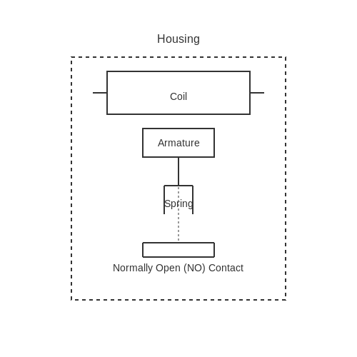
2.2 Solid State Relays
In the realm of electrical switching, solid state relays (SSRs) exemplify an advancement over traditional electromechanical relays. Unlike their electromechanical counterparts that operate via coils and physical moving parts, SSRs utilize semiconductor devices to perform switching. This fundamental difference leads to superior performance characteristics such as faster switching times, longer life expectancy, and greater immunity to electromagnetic interference.
Understanding Solid State Relay Operation
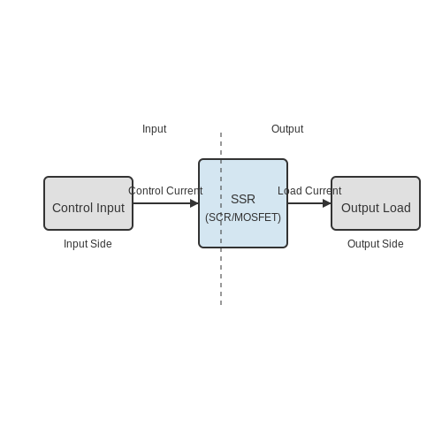
At its core, a solid state relay operates by controlling power via a semiconductor device, typically a silicon-controlled rectifier (SCR), a triac, or a MOSFET. When a small control current is applied to the input side of the SSR, it triggers the semiconductor to conduct, ultimately allowing a larger load current to flow through the output side. The unidirectional control achieved by SSRs means that they can be employed in various configurations such as on-off control or phase control, depending on the application's requirements.
Key Advantages of Solid State Relays
- Faster Switching Times: SSRs can switch states in microseconds compared to milliseconds or longer for mechanical relays.
- Extended Lifespan: With no moving parts, SSRs endure significantly lower wear and tear, often reaching operational lifetimes exceeding 10 million cycles.
- Reduced Electromagnetic Interference (EMI): The absence of physical contacts results in minimized electrical noise, which is crucial in sensitive electronic applications.
- Compact Size: SSRs are generally smaller than electromechanical relays for the same load current capacity, allowing for more compact circuit designs.
Practical Applications
Solid state relays have found their way into a multitude of applications across various industries. Their robustness and reliability make them ideal candidates for:
- Industrial automation systems, where precise control over machinery operations is critical.
- Heating applications such as temperature control in processes like plastic manufacturing or within HVAC systems.
- Lighting control in stage and architectural lighting systems, allowing for dimming and other effects without flickering.
- Communication systems, where the high-speed capability of SSRs can be utilized in data signal routing.
Design Considerations
While the advantages of solid state relays are compelling, several key design considerations must be addressed to optimize their use:
- Heat Dissipation: SSRs can generate heat during operation, especially under high load conditions. Ensuring proper heat sinking or cooling is crucial to maintaining performance and longevity.
- Voltage Isolation: Applications may require varying levels of isolation. Understanding the voltage ratings and selecting appropriate isolation strategies can improve safety and interoperability in mixed signal environments.
- Input and Output Voltage Compatibility: Select SSRs that match the control circuit and load side specifications to prevent component failure and ensure optimal performance.
As we continue to evolve in the fields of electronics and automation, solid state relays stand out as a compelling solution. Their architectural simplicity combined with operational efficiency empowers them to meet the demands of ever-increasing technological sophistication.
2.3 Reed Relays
Reed relays embody a unique class of electromechanical switches that capitalize on the properties of magnetism and electrical conduction. These devices are considered essential components in various electronic circuits, particularly where space-saving designs and reliability are paramount. At their essence, reed relays consist of two ferromagnetic contacts enclosed within a hermetically sealed glass envelope, which facilitates low-power and high-speed applications.
The operation of reed relays hinges upon the interaction of magnetic fields. When an external magnetic field—in most cases, produced by a coil energizing the relay—is applied, each reed, or contact, within the package is drawn towards the other, thus closing the circuit. The beauty of this process lies in its simplicity and efficiency. Once the magnetic field is removed, the contacts spring apart, interrupting the circuit once more.
Construction and Working Principle
The construction of a reed relay revolves around its key components: the reeds, the encasing glass, and the magnetic coil. The reeds are made from a ferromagnetic material, often alloyed with specific metals to bolster their magnetic properties. The choice of glass for encasing the components is particularly interesting; it prevents contamination from environmental elements while ensuring that the contacts maintain integrity over time.
When a voltage is applied across the coil, it generates a magnetic field that is concentrated in the gap where the reeds are located. This field attracts the reeds, leading to a contact closure. The following mathematical formulation aids in understanding the necessary conditions for the magnetic field strength.
In this formula, F represents the magnetic force exerted between the reed contacts, B is the magnetic flux density, A is the area of overlap of the reeds, and \mu_0 is the permeability of free space. Once the magnetic field is removed, the force acting on the reeds vanishes, allowing them to return to their default open state due to the tension of their suspended position.
Applications of Reed Relays
The practical applications of reed relays are extensive, primarily because of their ability to operate with minimal power and their quick switching capabilities. Common applications include:
- Telecommunications: Used for switching lines in telephony and in data transmission systems.
- Automotive: Incorporated in remote locking systems, alarm systems, and electronic control units (ECUs).
- Home Automation: Employed in smart devices to manage lighting, HVAC systems, and security alarms.
- Industrial Controls: Utilized to control high-voltage circuits while ensuring isolation for low-voltage control signals.
Moreover, innovations in reed relay technology have led to the development of solid-state versions which aim to combine the benefits of reed relays with the durability and longevity associated with semiconductor switches. These advancements illustrate the ongoing evolution and importance of reed relays in modern circuitry.
In conclusion, reed relays serve a significant role in various applications across industries due to their reliable operation, compact design, and efficiency. Understanding their construction and functionality not only aids in effective circuit design but also opens avenues for innovative applications in the realm of electronics.

2.4 Latching Relays
Introduction to Latching Relays
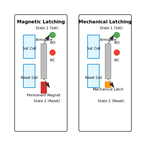
Latching relays, distinguished from their standard counterparts, are remarkable for their ability to maintain their state (either on or off) without continuous power consumption. Their operational structure often relies on a magnetic latching mechanism that enables them to remain in a particular state post-activation, a feature that offers significant energy savings and enhanced reliability in various applications. The dual-coil latching relay comprises two electromagnets and a movable armature that toggles between the two magnetizing states. This structure allows for a highly efficient design, suitable for applications where power conservation is critical. To understand the nuances of latching relays, it's essential to dive into their construction and operational principles.Operational Principles
When power is applied to a latching relay, the corresponding coil generates a magnetic field that moves the armature, sealing the relay's contacts in either the 'on' or 'off' position. The unique aspect lies in its ability to retain the armature's position even after the power supply is removed, unlike standard relays. The core components include:- Coils: Two coils are needed for switching between states.
- Armature: A movable iron piece that shifts based on magnetic fields.
- Springs: These restore the armature to its original position when required.
Applications of Latching Relays
Latching relays have found their significance in various high-demand scenarios, particularly in:- Energy Conservation: Used in energy-efficient lighting systems and appliances where constant power is impractical.
- Automated Control Systems: Ideal for control applications in industrial settings; they help maintain desired states based on prior conditions.
- Safety Systems: Used in alarm systems and emergency shutdown circuits to ensure systems remain in a safe state.
- Home Automation: Key element in smart home devices to provide convenience without the continuous energy drain.
Conclusion
In summary, latching relays represent a significant advancement in relay technology, offering energy efficiency and enhanced functionality through their ability to maintain their state without continuous power. The understanding of their operational principles lays a foundation for utilizing these components effectively in contemporary electronic applications. As technology progresses, latching relays are poised to play an increasingly vital role across diverse fields.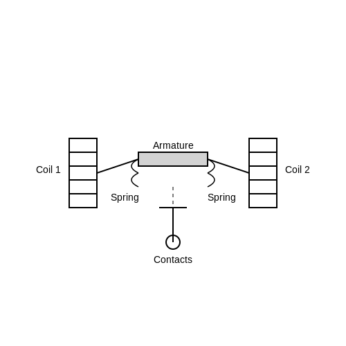
3. Components of a Relay
3.1 Components of a Relay
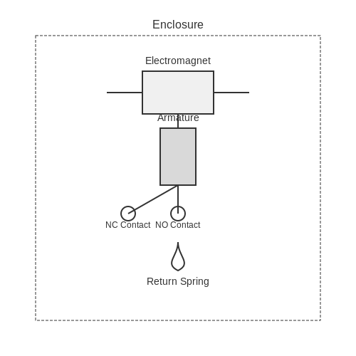
The electrical relay is a crucial component in both analog and digital electronic circuits, functioning fundamentally as an electromechanical switch. Understanding the key components of a relay is essential for engineers and researchers who design systems that incorporate them. This section delves into the integral parts that constitute a relay, highlighting their functions and interactions, which ultimately culminate in the relay's operation.
The Electromagnet
At the heart of most relays lies the electromagnet. This component converts electrical energy into magnetic energy when current flows through its coil. The design typically consists of a coil wound around a magnetic core, which amplifies the resulting magnetic field. When the coil is energized, it generates a magnetic field strong enough to move the relay armature, hence switching the contacts.
The relationship governing the electromagnet can be characterized using Ampère's Law, which states that the magnetic field strength \( H \) around a closed loop is proportional to the electric current \( I \) flowing through it:
where \( N \) is the number of turns in the coil, \( I \) is the current in amperes, and \( l \) is the length of the magnetic path. Essentially, the configuration of the coil, along with the material of the core, directly influences the efficiency and responsiveness of the relay.
The Armature
The armature is a pivotal mechanical component that connects the magnetic circuit to the mechanical switching mechanism. When the electromagnet is energized, the armature is pulled toward the coil by the induced magnetic field, a movement that either opens or closes the contacts within the relay. The mechanical design of the armature is critical, as it must be precisely balanced and capable of overcoming the return springs that ensure the relay defaults to its 'off' position when not energized.
The Contacts
Relay contacts are the conductive parts that complete or interrupt the electrical circuit based on the position of the armature. They come in various configurations, such as normally open (NO) and normally closed (NC). The choice of contact material (such as silver, gold, or nickel) impacts the relay's performance, reliability, and lifespan. Understanding the electrical characteristics and limitations of these materials is vital for applications that demand high levels of reliability, such as in automotive or industrial systems.
The Spring
Most relays feature a return spring that returns the armature to its original position once the coil is de-energized. This component ensures the relay does not remain in its activated state when current is cut off, providing stability and reliability. The spring's strength and design dictate the response time of the relay, which can be crucial in time-sensitive applications such as automotive safety mechanisms.
Enclosure
Finally, the enclosure of a relay serves multiple functions: it protects the internal components from environmental factors such as dust and moisture, provides structural integrity, and can also contribute to electromagnetic shielding. The selection of materials and the design of the casing can significantly affect the relay’s mechanical resilience and thermal stability, which is vital in ensuring reliable performance under varying operating conditions.
Understanding these components and their interplay not only enhances your ability to select the appropriate relay for specific applications but also aids in troubleshooting and optimizing existing systems. As you engineer solutions that require switching capabilities, consider how each aspect can affect performance, integrating these insights into your design philosophy.
3.2 Materials Used in Relay Design
In the intricate world of electrical relays, the choice of materials plays a pivotal role in determining their performance, reliability, and longevity. Various components of a relay—such as the coil, armature, contacts, and frame—require specific material properties to fulfill their intended functions under varying operational conditions. This section elucidates the materials commonly employed in relay design, emphasizing their distinct characteristics and contributions to the overall functionality of relays.
Coil Materials
The coil of a relay is fundamental to its operation, serving to generate a magnetic field when an electrical current flows through it. Typically, copper is the material of choice due to its exceptional conductivity, which enables efficient operation with minimal resistive losses. In some high-temperature or high-frequency applications, aluminum coils may be utilized because of their lighter weight and lower cost. However, aluminum generally exhibits lower conductivity than copper, which can affect the relay's performance.
Armature Materials
The armature is responsible for moving in response to the magnetic field generated by the coil. Common materials for armatures include low-carbon steel or iron, selected for their high magnetic permeability which enhances the relay's efficiency by allowing for a strong magnetic field to actuate the armature with lower energy consumption. The magnetic properties of these materials also minimize hysteresis losses, thus improving overall switching speed.
Contact Materials
The contacts in a relay must withstand wear and corrosion while ensuring reliable electrical conduction. Commonly used materials include:
- Silver: Utilized for its excellent conductivity and resistance to oxidation. Silver contacts can effectively handle low power applications but can experience wear from pitting in high-load environments.
- Gold: Often applied in micro-relays or signal applications due to its low contact resistance and high corrosion resistance, although the expense might limit its use in larger or cost-sensitive relays.
- Nickel: Sometimes used as an underlayer in contact assemblies to improve adhesion and corrosion resistance, especially in combination with other materials like gold or silver.
To further enhance the durability and performance of contacts, various coatings may be applied. These coatings, such as rhodium or palladium, work to improve adhesion and further resist corrosion.
Frame and Housing Materials
The frame and housing of relays are designed to provide structural integrity and protect internal components. Common materials include:
- Plastic: Frequently used for lower-cost devices, plastic housings are lightweight, insulative, and resistant to corrosion, making them a popular choice in general applications.
- Metal: For robust designs, metals like stainless steel or aluminum are selected, delivering superior mechanical strength and electromagnetic shielding.
Combining different materials not only optimizes the performance of relays but also takes advantage of the properties unique to each type. Crafting a relay design thus becomes a balancing act between cost, performance, and application-specific needs.
As industries evolve and applications become more sophisticated, extensive research continues into new materials that can enhance performance, reduce weight, and improve the environmental resilience of relays. Innovations like composite materials and advanced alloys may shape future developments in relay technology.
3.3 Packaging and Form Factors
The effectiveness of electrical relays does not solely depend on their internal components or the mechanisms that drive their functionality; the way these devices are packaged plays an equally crucial role. Packaging refers to how a relay is housed, including its physical dimensions, materials used, and overall construction style. These factors significantly affect performance, reliability, and application suitability, particularly in complex systems where space and thermal management are integral concerns.Understanding Relay Packaging
Relay packaging serves multiple essential functions: it protects the sensitive internal components, facilitates electrical connections, aids in thermal management, and influences the electromagnetic performance. Relays are designed to endure environmental stresses such as temperature variations, vibrations, and possibly corrosive substances. Hence, the choice of materials—such as plastics, metal alloys, or ceramic composites—can also have implications for the relay's thermal conduction and dielectric properties. Beyond mere protection, the form factor or physical shape of the relay influences how it can be integrated into existing systems. Common forms include:- Plug-in Relays: These are designed to be inserted into sockets, simplifying replacement and providing ease of access for troubleshooting. They often come in standardized sizes.
- Surface Mount Relays: Specifically designed for use in printed circuit boards (PCBs), offering reduced footprint and ease of integration into compact electronic systems.
- Panel Mount Relays: These often have mounting brackets that allow them to be fitted into control panels, providing secure fastening and user-friendly connectivity.
- DIN Rail Mount Relays: These are designed to snap into DIN rails, facilitating efficient organization in industrial control environments.
Thermal Management Considerations
Heat generation is a vital consideration during relay operation. Electrical relays, particularly those handling significant current loads, can generate heat that affects their performance and lifespan. The thermal management strategy must correspond with the relay’s packaging. Common strategies include:- Thermal Conductivity: Choosing materials with higher thermal conductivity aids in dissipating heat more effectively.
- Heat Sinks: Utilizing external heat sinks attached to the relay casing can enhance cooling capabilities.
- Ventilation: Ensuring adequate airflow around relay components can prevent overheating, which is particularly crucial in densely packed environments.
Real-World Applications of Relay Packaging
In industries such as automotive, telecommunications, and industrial automation, the choice of relay packaging becomes pivotal. For instance, in automotive applications, relays often encounter harsh environments including high humidity and temperature fluctuations. Here, water-resistant and durable materials are essential. Similarly, in the telecommunications sector, where high-speed data transmission is key, surface mount relays are frequently employed to save space on PCBs while ensuring reliable performance under varying load conditions. Manufacturers of relays also continually adapt their packaging strategies based on evolving technologies and user demands, contributing to enhanced functionality and integration in smart devices. In conclusion, the packaging and form factors of electrical relays are critical elements that can influence their functionality, reliability, and suitability for specific applications. Understanding these aspects can empower engineers and designers to select and implement relays that meet the stringent requirements of modern electronic designs.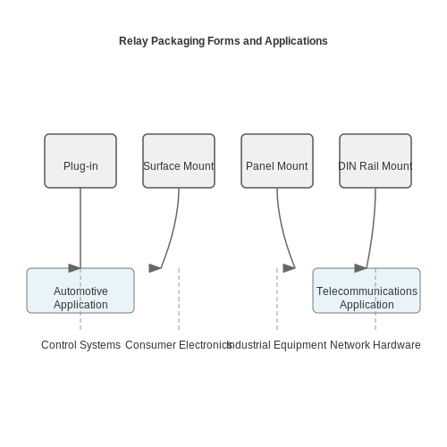
4. Coil Voltage and Current
4.1 Coil Voltage and Current
An electrical relay functions as an electromechanical switch; it utilizes a coil to generate a magnetic field when a voltage is applied. Understanding the relationship between coil voltage and current is essential in both designing and effectively utilizing relays in various applications, ranging from simple automation to complex industrial controls.
Coil Voltage Characteristics
The coil, typically made of insulated copper wire, has specific voltage ratings, often denoted as the coil voltage. This voltage is critical because exceeding it can lead to overheating, insulation breakdown, and eventual coil failure. Generally, relay coils are available in several common voltages, such as 5V, 12V, 24V, and 120V AC or DC.
Voltage Ratings and Applications
Different voltage ratings allow for flexibility in relay applications:
- Low voltage (e.g., 5V to 24V): Often used in electronic signals and control circuits.
- High voltage (e.g., 120V): Common in industrial applications where relays may control larger electrical loads.
It’s imperative that the selected voltage matches the relay’s voltage rating to ensure reliable operation. A mismatch can lead to inefficient performance or damage.
Coil Current Considerations
The current flowing through the relay coil, known as coil current, is another vital aspect. This current can be calculated from the coil’s resistance and the applied voltage using Ohm’s law. The relationship can be expressed mathematically as:
where:
- I: Coil current (A)
- V: Applied coil voltage (V)
- R: Coil resistance (Ω)
Deriving the Current from Coil Specifications
When designing a circuit incorporating relays, you need to consider both the voltage rating and the internal resistance of the coil:
Suppose you have a relay rated for 12V with a coil resistance of 240Ω. Using the formula above, we can derive the coil current:
This calculation highlights that a 12V relay will draw 50mA of current when properly activated.
Power Consumption of Relay Coils
The active power consumed by the relay coil can be derived from the product of the voltage and the current:
Substituting our previous results, we find:
This means the relay coil consumes 0.6 watts. Knowing the power consumption is crucial for designing power supply circuits, ensuring that the component can handle the load without overheating or failing.
Practical Relevance and Design Implications
When designing a circuit with relays, it is imperative to select the correct coil voltage and ensure that the power supply can deliver adequate current. Relay coils can often exhibit non-linear characteristics due to magnetic saturation, especially in high power applications. Engineers must account for these characteristics to ensure longevity and reliability of the relay. Knowledge of coil voltage and current also impacts the choice of control circuits, such as transistors or microcontrollers that interface with the relay.
In real-world applications, one common use is in automotive systems where relays control various electrical devices safely by isolating low-power control electronics from higher-power circuits.
The interplay of coil voltage and current in relay operation plays a foundational role in electrical engineering, impacting everything from simple smart home automation systems to complex industrial control units and power distribution networks.
4.2 Contact Ratings and Configurations
In the realm of electrical relays, understanding contact ratings and configurations is paramount not only for ensuring reliability but also for optimizing performance. The contact rating of a relay defines the maximum load it can handle, impacting both safety and efficiency in various applications ranging from mundane household devices to complex industrial machinery.Contact Ratings
The contact rating specifies the electrical load that the relay can safely manage, encompassing both voltage and current limits. These ratings are typically provided in two forms:- AC Ratings: Indicate the maximum voltage and current for alternating current applications.
- DC Ratings: Define the limits for direct current applications.
- The thermal limit of the contact material
- The wear and fatigue from repetitive operations
- The dielectric strength necessary to prevent arcing between contacts
Configurations of Relay Contacts
Relays utilize various contact configurations to suit different operational requirements. Understanding these configurations aids in selecting the correct type for a given application. The most common configurations include:- Normally Open (NO): Contacts are open in their default state and only close during relay activation, allowing current to flow.
- Normally Closed (NC): Contacts are closed in the default state, interrupting current flow when the relay is activated.
- Changeover (CO): These relays provide a single set of contacts that can function as either NO or NC depending on how the relay is wired. This versatility makes CO relays particularly useful in automation systems.
Real-World Applications
The applications of relay contact ratings and configurations span numerous fields, reflecting the balance between design choice and operational demands. In commercial and industrial settings:- Automotive Relays: In automotive systems, both NO and NC contacts are employed for safety mechanisms like automatic headlight shut-off or door locking systems.
- Industrial Automation: CO devices are often favored in complex automation systems, where the need arises to switch between different circuits within a single unit.
4.3 Switching Speed and Delay
The switching speed and delay of electrical relays are crucial performance parameters impacting the efficacy and responsiveness of a relay in varying applications. These characteristics define how quickly a relay can transition from a non-conducting state to a conducting state (and vice versa), directly influencing response times in control circuits. In this subsection, we will explore the fundamental aspects of relay switching speed, the causes of delays, and their implications in practical scenarios.Understanding Switching Speed
The switching speed of a relay refers to the time it takes for the relay contacts to change state when an electrical signal is applied. This speed is often characterized by a combination of the pull-in time and the drop-out time:- Pull-In Time: The duration it takes for the relay to activate once the control voltage is applied.
- Drop-Out Time: The time it takes for the relay to return to its original state after the control voltage is removed.
Factors Influencing Delay
Delays in relay operation can result from various factors, each affecting the overall performance. Key contributors to delay include:- Mechanical Components: The mass and friction of moving parts can slow down actuation, leading to longer switching times.
- Electromagnetic Response: The inductance and resistance of the coil determine how quickly the electromagnetic field can develop, impacting the pull-in time.
- Relay Type: Different relay designs, such as electromechanical vs. solid-state, offer varying switching speeds. Solid-state relays (SSRs) typically switch faster due to the absence of moving parts.
Applications and Practical Relevance
The switching speed and delay are particularly critical in applications where timing is essential, such as in automation systems, communications, and protective relaying in electrical grids. For instance, in high-speed industrial automation, even a few milliseconds can significantly impact performance and efficiency. Furthermore, in the domain of control systems, relays with faster switching capabilities facilitate more accurate feedback loops, improving system stability. In contrast, excessive delays can lead to the undesired operation of mechanical systems, potentially causing damage to machinery or compromising safety. As technology progresses, manufacturers are continually innovating to develop relays with enhanced speeds and reduced delay times. These innovations not only cater to the demands of modern-day applications but also extend the operational lifespan and reliability of the devices. In conclusion, understanding the intricacies of switching speed and delay is vital for engineers and researchers involved in designing and optimizing relay systems. By effectively managing these parameters, one can significantly enhance the performance and efficiency of various electrical applications.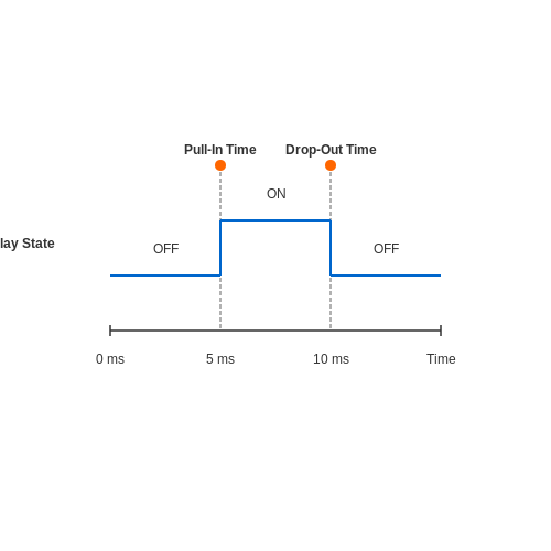
4.4 Life Cycle and Durability
The life cycle and durability of electrical relays are central to their effectiveness in various applications, particularly in industrial settings where reliance on longevity and performance consistency is critical. A thorough understanding of these parameters is crucial for advanced-level readers, as it influences both the design of relay systems and their practical deployment in electronic circuits.
Understanding Life Cycle
The life cycle of an electrical relay typically refers to the total number of operations a relay can execute before failure, which is influenced by several factors, including mechanical and electrical stresses. The two primary types of relay life cycles are:
- Mechanical Life: This refers to the number of times a relay can switch without electrical load. It is primarily determined by the wear and tear of mechanical components during actuation.
- Electrical Life: This encompasses the number of operations under rated load conditions. This factor is crucial since it reflects failures that could happen due to arcing, contact wear, and thermal effects.
The life expectancy of typical electromechanical relays can vary from thousands to millions of cycles depending on the construction, materials used, and operational conditions. For example, high-quality relays designed for heavy-duty applications may achieve mechanical life ratings of over 10 million operations, whereas standard relays may only offer hundreds of thousands.
Factors Affecting Durability
Understanding the factors that affect the durability of relays is pivotal for engineers and designers seeking to optimize system performance. Key influences include:
- Contact Material: The choice of contact materials determines the abrasive and corrosive wear rates. For example, silver alloy contacts provide good conductivity but may tarnish over time, impacting reliability.
- Load Characteristics: The type of load—inductive, capacitive, or resistive—affects the experiences of contacts during switching. Inductive loads can generate high voltage spikes, leading to contact welding.
- Environmental Conditions: Extreme conditions such as high humidity, temperature variations, and corrosive atmospheres can significantly degrade relay performance. Sealed or hermetically sealed relays can help mitigate these effects.
- Duty Cycle: Continuous versus intermittent operation will impact the heat generated within the relay and overall wear and tear.
Durability Testing
To quantify the durability of a relay, manufacturers conduct extensive testing, often simulating real-world conditions. Common methodologies include:
- Life Testing: Continuous operation of the relay under specified conditions until failure is observed, documenting the mode and nature of failure.
- Environmental Testing: Subjecting relays to extreme temperatures and humidity levels to assess their performance consistency in non-ideal scenarios.
- Contact Resistance Measurement: Periodically measuring the electrical resistance of contacts during testing to identify degradation trends over time.
Not only does understanding life cycle and durability enhance the reliability of electrical systems, but it also aids in minimizing maintenance costs and downtime in industrial applications. For instance, in automotive relay systems, this knowledge is vital for ensuring safety and performance in critical functions such as braking and ignition systems.
In embracing these considerations, engineers can make informed decisions about relay selection, design, and implementation, ultimately contributing to the advancement of reliable and efficient electronic systems.
5. Industrial Automation
5.1 Industrial Automation
Electrical relays play a pivotal role in the landscape of industrial automation, providing a reliable method for controlling large electrical loads through a small input signal. At their core, relays act as electromechanical switches that utilize electromagnetic fields to operate. This allows for safe and efficient manipulation of electrical circuits, especially in environments where direct human interaction poses safety risks.
In modern automation systems, the traditional relay has evolved into various forms, including solid-state relays (SSRs) and programmable logic relays (PLRs). Each type brings unique benefits to industrial applications, ranging from improved response times to increased durability against wear and tear. Understanding these advancements is crucial for engineers seeking to optimize control systems within industrial settings.
Relay Types and Their Applications
Relays can be segmented into several categories based on their operating principles. The most commonly used types include:
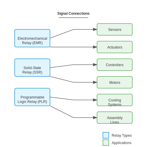
- Electromechanical Relays (EMRs): These relays use mechanical components to switch circuits and can handle high voltages and currents. Their applications range from simple on/off control to complex automation processes as in motor control circuits.
- Solid-State Relays (SSRs): Operate without moving parts, providing faster switching speeds and longer operational life due to their robust construction. They are ideally suited for applications requiring rapid on/off cycling, such as in heating elements and lighting control.
- Programmable Logic Relays (PLRs): Combine the functionalities of traditional relays with programmable capabilities. PLRs are often utilized in systems that require multiple switching operations and complex control logic, such as automated assembly lines.
Integration in Automation Systems
The integration of relays into larger automation systems is a key factor contributing to efficiency and reliability. By interfacing with sensors and controllers, relays provide the necessary control over actuators, motors, and other devices. For instance, when a temperature sensor detects a rise above a preset threshold, it can send a signal to the relay, which subsequently activates a cooling system.
Consider a manufacturing line where various processes must operate in sync. Here, relays facilitate the interlocking of machines, ensuring one process does not commence until the previous one has successfully completed its cycle. This not only enhances operational safety but also improves efficiency by preventing bottlenecks.
Challenges and Considerations
While the advantages of using relays in industrial automation are substantial, various challenges must be addressed. For example, relay contacts can degrade over time due to sparking or arcing, particularly in high inductive loads. This can lead to premature failure unless appropriate suppression methods, such as snubber circuits, are employed.
Furthermore, the choice between electromagnetic and solid-state relays can influence control system performance. Engineers must assess factors such as load characteristics, switching frequency, and environmental conditions to select the appropriate relay type for their specific application. Misjudgments in selection can lead to inefficiencies or system failures, emphasizing the necessity for thorough understanding and planning in automation system design.
In conclusion, the electrical relay is a cornerstone of industrial automation, facilitating control and ensuring operational safety. As technology advances, the capabilities of relays continue to expand, allowing for more dynamic and efficient automation systems. Engineers and designers must stay abreast of these developments to harness the full potential of relays in their automation applications.
5.2 Home Automation
In the realm of modern technology, the significance of home automation systems is rapidly growing, driven by the convergence of information technology and traditional electrical systems. At the core of many of these automated solutions lies the electrical relay, a device characteristic of its ability to isolate and control high power loads with low power signals. This capability not only enhances energy efficiency but also adds a layer of safety for home environments.
As we delve deeper into the implications of electrical relays within home automation, it's paramount to understand that they serve more than just the role of switches. Their operational flexibility allows for remote control, timing functions, and integration with smart home systems, thereby optimizing the management of electrical appliances across various environments.
Understanding Home Automation Systems
Home automation systems enable various devices within a household to communicate and be controlled via a centralized system. Typical applications may include lighting control, heating, surveillance, and security systems. The role of relays here can be multifaceted — from controlling individual appliances to managing entire electrical circuits that encompass multiple devices.
Relay Configuration in Home Automation
Relays can be categorized based on their function and structure. The two most relevant types in home automation systems are:
- Electromechanical Relays (EMRs): These use an electromagnetic coil to mechanically operate a switch, making them suitable for high-power devices.
- Solid State Relays (SSRs): Utilizing semiconductor devices to switch electronics on and off, SSRs are preferred for silent operation and longevity.
Both types have their specific places in home automation; for example, EMRs may be applied to control incandescent lighting, while SSRs could manage LED systems where quick switching with less heat dissipation is crucial.
Integration with Smart Home Protocols
Electrical relays are often integrated with prevalent smart home communication protocols such as Z-Wave, Zigbee, and Wi-Fi. This integration allows devices equipped with relays to be controlled remotely through smartphones or voice assistants. Understanding the communication protocols is essential for addressing interoperability challenges. For example, employing a relay module that supports both Z-Wave and Zigbee can enable devices from different manufacturers to work together seamlessly.
Example Application: Smart Lighting Control
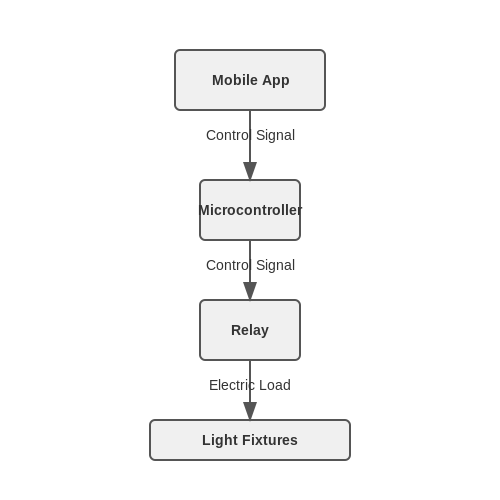
Consider a home lighting system where relays are used to control lighting circuits. Through a smart hub, users can program schedules or change lighting settings in real-time based on external parameters such as ambient light levels or occupancy status. The construction of such a system typically involves:
- Connecting the electrical loads (light fixtures) to a relay,
- Linking the relay to a microcontroller that communicates via a chosen protocol,
- Implementing a user interface through a mobile app that allows for interaction with the system.
This interactivity not only enhances user convenience but also contributes to energy savings and security. For instance, scheduled lighting can simulate occupancy during the night when owners are away, thereby deterring potential intruders.
Future Trends in Home Automation with Relays
The ongoing evolution of home automation continues to influence the use of relays. Emerging trends include:
- Greater incorporation of IoT technologies, allowing for even more intelligent control systems that adapt to user behavior.
- The integration of renewable energy sources, where relays manage direct current (DC) outputs from solar panels, optimizing energy consumption.
- Increased focus on cybersecurity measures, vital for safeguarding smart home devices against unauthorized access.
With these advancements, the future of electrical relays in home automation becomes increasingly promising, as they adapt to meet modern demands for efficiency, user-friendliness, and security.
In conclusion, the integration of electrical relays into home automation systems exemplifies the synergy of technology and efficiency, paving the way towards smart living environments. This intricate balance highlights the innovative use of simple components, redefining the concept of convenience and control within our everyday lives.
5.3 Automotive Applications
Electrical relays play a crucial role in automotive applications, serving as fundamental components in various vehicle systems. Their primary function is to control high-current circuits using low-current signals, which allows for the safe and effective management of numerous automotive functions. Understanding their utility necessitates an examination of both their operational principles and their integration into automotive technology.
Operating Principles of Relays in Vehicles
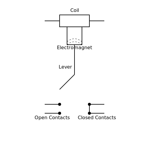
At the core of any relay is the electromagnetic mechanism that activates a switch via an electromagnet. When an electrical current flows through the coil, it generates a magnetic field, which in turn pulls a lever that closes or opens contacts. This switching action allows relays to manage components such as headlights, electric windows, and ignition systems efficiently.
The power-handling capability of a relay, often specified in terms of its rated voltage and current, is vital for automotive applications, where devices can draw significant power. For instance, a typical automotive relay may handle up to 30 amps at 12 volts, making it suitable for high-power devices. Its compact size is also advantageous in the spatially constrained environment of a vehicle.
Types of Automotive Relays
There are several types of relays used in vehicles, each tailored for specific applications:
- Standard Relays: Commonly used for lighting and accessory controls.
- Heavy-Duty Relays: Designed for high-load applications such as starter motors.
- Micro Relays: Ideal for space-constrained designs, often found in modern cars that demand compact electronic circuitry.
- Solid-State Relays: Utilized for high-speed switching and reliability, often in sophisticated control systems.
Applications in Modern Vehicles
Electrical relays are instrumental across a variety of automotive functions:
- Lighting Control: Relays manage the operation of headlights, taillights, and turn signals, allowing for robust control over high-current demands without taxing the ignition circuit.
- Starter Motors: Heavy-duty automotive relays are crucial for controlling starter motors, enabling vehicles to commence operation efficiently.
- Window Mechanisms: Electric window lift systems utilize relays to control the motors that raise and lower glass windows, ensuring safe operation without risking overloads.
- Climate Control: In climate control systems, relays govern operation of the compressor and fans, facilitating effective temperature regulation within the cabin.
Reliability and Fail-safes
The reliability of automotive relays is paramount. Manufacturers implement fail-safes to prevent potential circuit failures. For example, in a scenario where a relay fails to engage, vehicles are designed with redundant pathways, or backup systems, that maintain essential functions, ensuring safety and usability. This redundancy is particularly critical in safety features, such as airbags and anti-lock braking systems (ABS), where failure can lead to hazardous outcomes.
Future Trends in Automotive Relay Technology
As vehicles transition towards increased automation and electrification, the role of relays is evolving. With the rise of electric vehicles (EVs) and hybrid technologies, developers are adapting relay designs to manage higher voltages and ensure greater energy efficiency. Innovations in solid-state relay technology and electronics are paving the way for more efficient, reliable, and compact systems that integrate seamlessly with advanced automotive systems, such as advanced driver-assistance systems (ADAS).
In conclusion, electrical relays are indispensable in automotive applications, serving as vital elements in the interplay between user control and component operation. As technology advances, the evolution of relay design and application will continue to influence automotive engineering, emphasizing safety, reliability, and efficiency.
5.4 Safety Systems
Electrical relays serve as critical components in various systems, ensuring not only the proper operation of electrical circuits but also the safety of both users and equipment. This subsection elaborates on the role of safety systems in relation to electrical relays, highlighting their practical relevance, functionality, and design principles.
Importance of Safety Systems
In any electrical application, safety systems are paramount. Their primary function is to prevent hazardous situations stemming from faults or unexpected conditions, which could lead to equipment damage, injury, or fatal accidents. Electrical relays, through their contact mechanism, facilitate the isolation of electrical circuits during unsafe conditions, effectively acting as switches that will open or close the circuit based on predefined safety thresholds.
Types of Relays in Safety Applications
Several relay types are specifically designed with safety in mind, including:
- Mechanical Relays: These are traditional relays that use electromagnetic principles to operate. They are effective for applications that require simple on/off controlling but may have slower response times.
- Solid-State Relays (SSRs): Unlike mechanical relays, SSRs use semiconductor devices to switch circuits and offer faster response times and greater durability, making them ideal for applications requiring high reliability.
- Safety Interlock Relays: These are designed with specific functional features that comply with stringent safety standards, ensuring that only safe operation states are permissible.
The choice of relay type depends significantly on the application's safety requirements and operational conditions.
Design Considerations for Safety Systems
When designing safety systems involving relays, several critical factors must be taken into account:
- Redundancy: Incorporating multiple relays or using a relay in conjunction with other safety devices can enhance system reliability and fault tolerance.
- Testing and Maintenance: Implementing periodic testing routines ensures that safety features are operational, mitigating risks associated with device failures.
- Sensitivity and Response Time: Relays must be sensitive enough to detect hazardous conditions quickly and respond accordingly, which requires careful selection based on the application's nature.
Real-World Applications
Safety systems incorporating electrical relays are ubiquitous across various industries, including:
- Industrial Equipment: In manufacturing, relays ensure machinery is shut down promptly in response to fault conditions, preventing accidents.
- Aerospace Systems: Relays play crucial roles in avionics, ensuring fail-safe operations through redundant systems.
- Automotive Safety: Modern vehicles use relays to control safety features, including airbag deployment and anti-lock braking systems, enhancing passenger safety.
Conclusion
In summary, safety systems that integrate electrical relays form the backbone of a secure electrical environment. Through careful attention to design and appropriate selection of relay types, engineers can greatly mitigate risks in a variety of applications, ensuring safety and reliability in the face of potential hazards.
6. Relay Control Circuits
6.1 Relay Control Circuits
In the domain of electrical engineering, relay control circuits are essential for enabling and controlling various devices and systems. By using electromagnetic switches, relays allow for the manipulation of high-voltage or high-current loads using low-power control signals, rendering them vital in numerous applications such as automation and safety systems.
Understanding the functionality of relay control circuits requires insight into the working principles of relays. A relay generally consists of a coil of wire that generates a magnetic field when current passes through it, mechanically actuating a set of contacts that either open or close a circuit. The ability to design and implement these circuits effectively requires knowledge of both the electrical characteristics of the relay components and the specific requirements of the application at hand.
Basic Relay Control Circuit Configuration
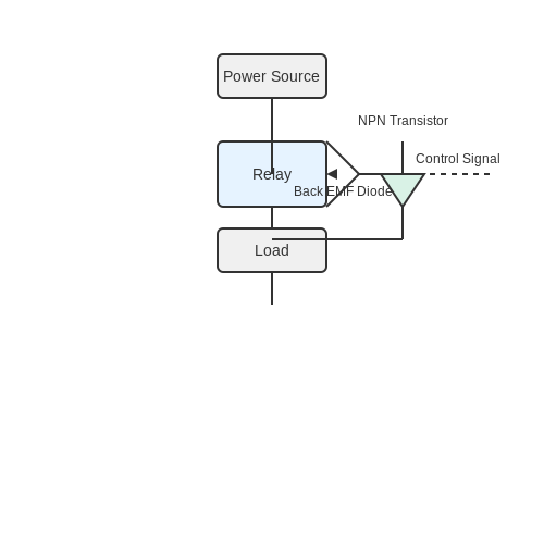
A fundamental relay control circuit comprises a DC or AC power source, a relay, and a load device. The most basic configuration includes:
- Power Source: Supplies the necessary voltage for the relay coil and load.
- Relay: Acts as an intermediary, where the coil energizes to close or open contacts.
- Load: The device that the relay controls (e.g., motor, lamp).
When a control signal is applied to the relay coil, the resulting magnetic field either makes or breaks the circuit through the load, which is essential for controlling larger power devices safely and efficiently.
Control Signal Types
The control signal to actuate the relay can take multiple forms depending on the application requirements:
- Manual Switch: A physically operated switch can provide the necessary control signal.
- Microcontroller Output: Digital signals from microcontrollers are common in automated systems, where logic levels can be used to energize the relay.
- Sensor Integration: Relays can be controlled based on inputs from sensors, allowing for conditions-based switching.
Relay Driving Circuits
In most cases, the control signal will not be sufficient to drive the relay directly. Hence, we employ driving circuits to amplify the signal. A typical driving circuit might involve:
- A transistor (NPN or MOSFET) as an electronic switch that is triggered by the control signal.
- Diodes to prevent back EMF from damaging sensitive components when the relay is de-energized.
In the case of an NPN transistor, assume the control signal is supplied to its base. The transistor will conduct, allowing current through the relay coil when the control is high, effectively energizing the relay. The relationship can be expressed using Kirchhoff’s law and Ohm’s law.
Where \(I_{coil}\) is the current through the relay coil, \(V_{supply}\) is the power supply voltage, \(V_{CE}\) is the collector-emitter saturation voltage of the transistor, and \(R_{coil}\) is the resistance of the relay coil.
Practical Implementation Considerations
When designing relay control circuits, several practical considerations must be addressed:
- Relay Ratings: Ensure the relay's voltage and current ratings match or exceed those of the load.
- Signal Isolation: Opto-isolators can be utilized for effective signal isolation between control and load circuits.
- Debouncing: If using mechanical switches, debouncing techniques are advisable to prevent false triggers.
Relay control circuits find applications across diverse industries, including automotive systems, home automation, industrial machinery, and safety systems. As technology evolves, the integration of microcontrollers and digital logic further enhances the capabilities and functionalities of these circuits, paving the way for smarter and more efficient applications.
6.2 Interfacing Relays with Microcontrollers
Electrical relays serve as crucial electromechanical devices that enable the switching of electrical circuits by low-power signals. Choosing to interface a relay with a microcontroller brings about significant advantages, particularly in applications such as home automation, robotics, and industrial control systems. This section delineates the principles involved in effectively interfacing these two components, providing insights that are critical for successful implementation.
Understanding Relay Functionality
Relays operate through electromagnetic mechanisms, allowing a very low control voltage to manage a much larger load voltage and current. The core components of a relay include:
- Coil: When an electrical current passes through the coil, it generates a magnetic field.
- Armature: The movement of the armature, actuated by the magnetic field, either connects or disconnects the circuit.
- Relay contacts: These can be normally open (NO) or normally closed (NC) to control the intended output circuit.
As evident, relays provide electrical isolation between a control circuit involving the microcontroller and a power circuit that drives higher loads, thus protecting the microcontroller from potentially damaging voltages. This isolation is particularly vital in safety-critical applications.
Required Components for Interfacing
Before interfacing a relay with a microcontroller, ensure you have the following components:
- Microcontroller (e.g., Arduino, Raspberry Pi)
- Relay module or standalone relay
- Opto-isolator (optional for additional protection)
- Power supply suitable for the relay's coil voltage
- Diode (e.g., 1N4007 for flyback protection)
- Transistor (to drive the relay, e.g., NPN transistor such as 2N2222)
- Resistor (typically 1kΩ for base current limiting)
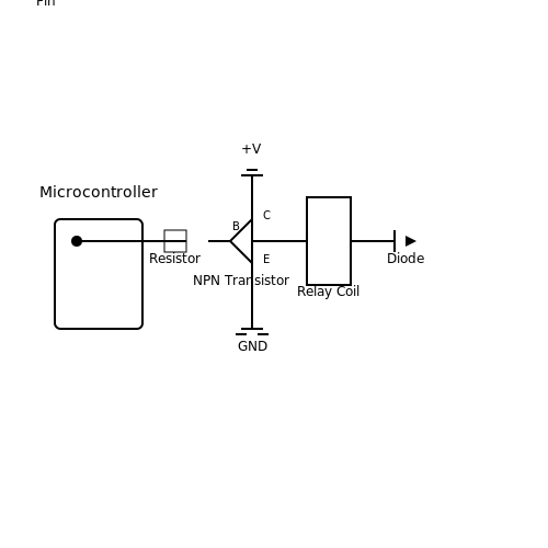
Wiring Diagram
The wiring diagram illustrates how to connect the microcontroller to the relay module. The essential components to connect include:
- Microcontroller output pin to the base of the transistor through a resistor.
- Transistor collector to one terminal of the relay coil.
- The other terminal of the relay coil to the positive terminal of the power supply.
- Transistor emitter to ground.
- A diode in parallel with the relay coil for flyback protection.
The diagram also shows how the microcontroller can control incoming and outgoing AC or DC loads through the relay contacts.
Programming the Microcontroller
The microcontroller needs to be programmed to control the relay effectively. The software logic typically involves:
- Setting the appropriate microcontroller pin as an output.
- Using digital write commands to turn the relay on (set pin HIGH) and off (set pin LOW).
Here is a simple example of code for an Arduino-based system:
int relayPin = 7; // Pin connected to relay

void setup() {
    pinMode(relayPin, OUTPUT); // Set relayPin as output
}

void loop() {
    digitalWrite(relayPin, HIGH); // Turn relay ON
    delay(1000); // Keep it ON for 1 second
    digitalWrite(relayPin, LOW); // Turn relay OFF
    delay(1000); // Keep it OFF for 1 second
}
In this example, the relay toggles every second, controlling any connected device while providing precise control through the microcontroller.
Application Considerations
Relay interfacing is essential across many applications such as:
- Home Automation: Automating lights and appliances based on user input.
- Industrial Control: Managing heavy machinery safety protocols.
- Robotics: Controlling motors or other peripherals that require higher voltages.
Given the reliability and efficiency of relays in controlling power loads, they remain a preferred choice in environments where isolation and control are paramount.
In conclusion, the interplay between microcontrollers and relays not only showcases the dynamism of modern electronics but also emphasizes the critical need for understanding underlying principles for effective and safe applications.
6.3 Relay Protection Circuitry
Electrical relays, essential components in modern electronic systems, can be vulnerable to various types of faults. Therefore, incorporating protection circuitry into relay applications is crucial to enhance the reliability and lifespan of these devices. This section will delve into common protection strategies, highlighting their practical implementations and significance.
Understanding Relay Vulnerabilities
Relays typically consist of an electromagnetic coil and a set of contacts. When a voltage is applied to the coil, it generates a magnetic field, engaging the contacts and allowing current to flow through a secondary circuit. However, this process is not without potential hazards. Key vulnerabilities include:
- Overvoltage: High voltage spikes can damage the relay coil or contacts.
- Overcurrent: Excessive current can lead to heating, resulting in contact welding or failure.
- Inductive Kickback: The sudden interruption of current can create a high-voltage spike (back EMF) that poses risks to both the relay and surrounding components.
Protection Approaches
To mitigate these vulnerabilities, several protection methods can be employed. Each technique presents its own advantages and is selected based on specific application needs.
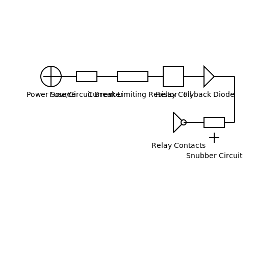
1. Snubber Circuits
A common solution for suppressing voltage spikes due to inductive loads is the implementation of a snubber circuit. Typically, a snubber consists of a resistor-capacitor (RC) network connected in parallel with the relay contacts. The capacitor absorbs the high-frequency voltage transients generated during the relay's switching actions. The resistor dampens oscillations while limiting the peak current through the capacitor.
The effectiveness of a snubber can be analyzed using the time constant of the RC circuit:
where \( \tau \) is the time constant, \( R \) is resistance, and \( C \) is capacitance. An appropriate design ensures minimal voltage across the relay contacts during operation.
2. Diode Protection
In DC relay applications, placing a flyback diode across the relay coil is a well-regarded method for protecting against inductive kickback. Upon de-energizing the coil, the diode provides a path for the induced current, preventing voltage spikes from damaging the power supply or control circuitry.
The operation can be characterized by the following relationship:
where \( L \) is the inductance of the coil and \( di/dt \) is the rate of change of current. This protection mechanism is critical for maintaining circuit integrity during the rapid switching of relays, providing robust transient voltage suppression.
3. Current Limiting Resistors
For applications where the relay must handle high inrush currents, such as lighting systems, implementing current limiting resistors is advisable. These resistors soften the impact of high currents at the moment of engagement, thereby minimizing stress on the relay contacts and extending lifetime.
The power dissipated by the resistors can be calculated using:
where \( P \) is the power dissipation, \( I \) is the current through the resistor, and \( R \) is the resistance value. Proper selection of resistor values is critical to achieve the desired level of protection.
4. Fuses and Circuit Breakers
In cases where overloads might occur, integrating fuses or circuit breakers into the relay system can provide a final layer of safety. These components act as fail-safes, interrupting the current flow in the event of excessive current, thereby protecting both the relay and the circuit it governs.
Choosing the right specifications involves understanding the maximum load that the relay is intended to control, as well as the characteristics of the load itself.
Conclusion
In summary, implementing an effective protection circuitry for electrical relays is vital to improve operational reliability and safety. By addressing vulnerabilities like overvoltage, overcurrent, and inductive kickback through various strategies, engineers can enhance not only the performance of relays but also the integrity of entire systems.
7. Common Relay Issues
7.1 Common Relay Issues
The electrical relay, a crucial component in both industrial and consumer electronics, is not immune to failure. Understanding the common issues that can arise with relay operation is essential for engineers and technicians tasked with system design, maintenance, or troubleshooting. This section will explore these prevalent problems, their causes, and possible mitigation strategies.
Mechanical Failures
Mechanical failures in relays can manifest in various ways, one of the most common being contact welding. This occurs when the relay contacts become fused together due to excessive current flow, rendering the relay inoperative.
- Causes: Overcurrent conditions, inadequate ratings, and environmental factors.
- Mitigation Strategies: Utilize relays with appropriate current ratings and incorporate protective devices, such as fuses or circuit breakers, to prevent excessive current flow.
Electrical Failures
Electrical failures may result from insulation breakdown or contact corrosion. Insulation breakdown happens when the voltage exceeds the dielectric strength of the insulation material, creating short circuits.
- Corrosion: This can particularly affect the relay contacts and may be accelerated by exposure to moisture or poor environmental conditions.
- Solutions: Deploy hermetically sealed or conformally coated relays in harsh environments to minimize exposure to corrosive elements.
Relay Coil Malfunction
Relay coils can also suffer from issues. A common problem is coil burnout, typically caused by overvoltage conditions. The thermal effect leads to insulation failure and eventual coil failure.
- Overvoltage Conditions: Caused by inappropriate power supply voltage or transients in the circuit.
- Preventive Measures: Use voltage regulation devices or add surge protection components to prevent transient damage.
Debouncing Issues
Debounce issues can arise when relays experience rapid on/off switching, commonly seen in mechanical contacts. When a switch is toggled quickly, it can create multiple unwanted signals, leading to erroneous switching operations.
- Resolution: Implement debounce circuits or software algorithms, depending on whether the relay interface is hardware or software-based.
Temperature Effects
The operational environment significantly influences relay performance. Temperature extremes can lead to erratic operation and shortened lifespan due to thermal expansion or contraction.
- Thermal Management: Promote proper thermal management through ventilation or cooling in high-temperature environments.
Understanding these common relay issues aids in designing robust circuits that incorporate relays effectively, ensuring reliability and longevity in applications ranging from automotive to industrial automation systems.
7.2 Testing Techniques
Testing electrical relays is essential for ensuring their proper operation and reliability in various applications. Effective testing techniques can help diagnose issues, validate specifications, and confirm the durability of the relays in circuit environments. Understanding these approaches allows engineers to optimize their designs while minimizing potential failures in critical systems.
Basic Testing Methods
The simplest form of testing involves typically applying a specified voltage and measuring the response of the relay. The primary goal is to verify whether the relay operates within its rated specifications.
Visual Inspection- Check for physical damage, corrosion, and proper connections.
- Inspect terminals for signs of overheating or solder joints for integrity.
- Look for any mechanical obstructions in moving parts.
Visual checks serve as a precursor to more sophisticated assessments.
Functional Testing
Functional testing involves assessing the relay’s performance under operational conditions. This stage often requires the use of test equipment such as a relay tester or multimeter with relay testing functionality.
- Connect the relay in a test circuit with voltages and loads aligning with operational conditions.
- Monitor the relay's action—in particular, measure the pull-in and drop-out voltages to ensure they are within specified limits.
For quantitative analysis, one may examine the response time, defined as the duration needed for the relay to switch from an off state to an on state, and vice versa. A rapid, consistent response is indicative of reliability in tactical applications such as automotive systems or industrial automation.
Electrical Testing Techniques
Electrical tests can be categorized based on the parameters measured. Key electrical tests include:
- Coil Resistance Measurement: Utilizing an ohmmeter to examine the relay's coil resistance ensures that the relay coil is intact without shorts or opens. The resistance value should align with manufacturer specifications.
- Contact Resistance Testing: This measures the resistance across the contacts when the relay is energized, highlighting the efficacy of the contact interface. Typically, this should be measured under load conditions to gain accurate readings.
Advanced Diagnostics
To enhance the reliability and longevity of relays, advanced diagnostic methods can be employed. These might include:
- Thermal Imaging: Enables the detection of hotspots due to excessive resistance in terminals or coils.
- Oscilloscope Analysis: Can visualize the voltage and current waveforms, allowing for the analysis of transient events during relay operation. This technique assists in identifying issues such as arcing or resonance that may occur during actuation.
Additionally, performing stress testing with parameters set beyond nominal conditions can help assess the robustness of a relay. This technique can point toward potential failure mechanisms under extreme conditions, vital for critical applications like aerospace or military specifications.
Automating Testing Processes
In modern applications, automated test equipment (ATE) plays a crucial role in enacting both functional and electrical tests at scale. By configuring ATE to execute a series of programmed tests, engineers can ensure that each relay produced meets stringent quality standards efficiently. This mechanization not only accelerates testing but also enhances accuracy and consistency, mitigating human error.
In conclusion, the selection of suitable testing techniques for electrical relays is pivotal to ensure their functionality and reliability. The deployment of both basic and advanced methodologies allows for comprehensive assessments, promoting improved design and guaranteeing superior performance in practical applications.
Where R denotes resistance, V represents voltage, and I signifies current. This fundamental relation can be pivotal in analyzing relay characteristics during electrical testing.
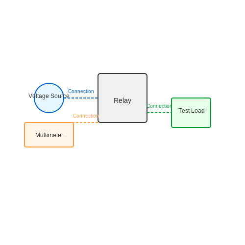
7.3 Maintenance and Replacement
Electrical relays play a critical role in various applications, from industrial systems to everyday devices. Their operational reliability and longevity depend significantly on proper maintenance and timely replacement. In this section, we will delve into best practices for maintaining relays, signs that indicate the need for replacement, and the methodologies for carrying out these processes effectively.
Understanding Relay Lifespan
The lifespan of an electrical relay can vary significantly depending on the type of relay used, the environment it operates in, and the load it carries. For instance, electromechanical relays typically have a rated lifespan ranging from 1,000,000 to 10,000,000 operations, while solid-state relays can last significantly longer due to fewer moving parts. However, external factors such as temperature, humidity, and vibration can drastically shorten their life expectancy.
Regular Maintenance Procedures
To ensure optimal performance, regular maintenance of relays is essential. Maintenance procedures can include:
- Visual Inspection: Conduct routine visual checks for signs of wear, corrosion, or damage to connections and terminals.
- Electrical Testing: Monitor the relay’s contact resistance and insulation resistance using specialized testing equipment.
- Functional Testing: Regularly activate the relay under operational conditions to ensure it responds correctly.
- Cleaning: Dust and contaminants can interfere with the relay’s operation. Utilize appropriate cleaning tools to maintain the integrity of connections.
By adhering to these maintenance practices, one can preemptively identify potential issues and prolong the relay's operational efficiency.
Identifying Signs for Replacement
Understanding when a relay has reached the end of its operational life is crucial to preventing failures in the systems they control. Common indicators include:
- Unresponsive Operations: If the relay fails to actuate or fails to disconnect properly, it could signal internal failure.
- Frequent Failures: A sudden increase in failure frequency typically indicates wear-out conditions and necessitates replacement.
- Abnormal Heat Generation: Excessive heat can be a sign of electrical overload or internal short circuits, often leading to failure.
- Physical Damage: Any visible damage, such as burnt contacts or melted plastic housings, warrants immediate replacement.
Replacement Best Practices
Replacing a relay is a critical task that requires precision to ensure reliability. Follow these guidelines for effective replacement:
- Power Down: Always disconnect power to the circuit before starting the replacement to avoid electrical hazards.
- Refer to Specifications: Use relays that meet or exceed the original specifications to maintain system integrity.
- Ensure Correct Orientation: Pay attention to the relay's orientation and pin configuration to prevent incorrect installation.
- Test After Replacement: After installing the new relay, conduct functional tests to confirm its operation under expected load conditions.
By observing these practices, one can minimize unexpected outages and maintain the reliability of the systems utilizing relays.
Conclusion
In summary, maintaining and replacing electrical relays involves understanding their lifespan, adhering to rigorous maintenance schedules, and recognizing the signs indicating replacement is necessary. As technology advances and systems become more complex, the importance of meticulous relay management cannot be overstated. By implementing effective strategies and practices, engineers and technicians can ensure that electrical systems operate smoothly and efficiently.
8. Recommended Books
8.1 Recommended Books
- Handbook of Electrical Components: Relays — This comprehensive guide offers detailed insights into relays, covering design principles, operational behavior, and applications within electronic systems. It is a valuable resource for understanding relay functionality in various circuit designs.
- Fundamentals of Electrical Drives — Though primarily focused on electrical drives, this book includes pertinent sections on the integration and role of relays in controlling drive systems, perfect for advanced-level understanding and system integration.
- Electrical Control Systems — This book dives into the design and implementation of control systems, with a strong focus on relay logic and its application in industrial systems, making it suitable for engineers and advanced students.
- Manufacturing Automation — A total approach guide to automation, this book includes a robust section on the role and integration of relays in automated systems, providing both theoretical insights and practical application strategies.
- Electronics: Basic, Analog, and Digital with PSpice — While this book targets a broad range of electronic components, it provides particular attention to relay-based circuits and their simulations using PSpice, offering practical exercises and examples.
- Electronics: Circuits and Systems — Ideal for graduate students, this text explores the principles behind electronic circuits, with a section dedicated to relay operations and the engineering concepts that support them.
- Power Electronics and Motor Drive Systems — This resource provides an advanced look at power electronics, presenting in-depth coverage on using relays in motor drives and related control system applications, perfect for both learning and research purposes.
8.2 Online Resources
- Electronics Tutorials - Relay Basics — Offers an introduction to the working principle of relays with diagrams, providing a solid foundation for anyone looking to understand relay operations in circuits.
- SparkFun - Relays — Detailed tutorial on different types of relays, including practical guides on integrating them into various projects, suitable for electronics enthusiasts and engineers.
- Omron - Relays: Frequently Asked Questions — An extensive FAQ section on relays covering technical details, troubleshooting, and applications, directly from a leading manufacturer in relay technology.
- TE Connectivity - Industrial and Automotive Relays — Provides insights into the latest relay technologies used in industrial and automotive applications, highlighting real-world use cases and technical specifications.
- ResearchGate - Relay Switching in Electric Systems — A research paper discussing the theoretical and practical aspects of relay switching in electric systems, beneficial for advanced readers seeking academic resources.
- All About Circuits - How Relays Work — A comprehensive article that dives deep into the physics behind relay operation, including coil construction and magnetic fields, serving as a bridge between theory and practical application.
- Clifford - Relays: Theory and Applications — A downloadable PDF document that provides in-depth analysis on relay theory, types, and applications across various industries, aimed at researchers and engineering professionals.
8.3 Research Papers
- IEEE Xplore: Intelligent Relay Systems — This research paper discusses state-of-the-art developments in intelligent relay systems, highlighting algorithms designed for improved fault detection and efficiency in varying electrical network conditions.
- ScienceDirect: Advances in Electrical Relay Technologies — A comprehensive examination of innovations in relay technology, offering insights into design improvements, sustainability considerations, and practical applications in modern energy systems.
- Elsevier - Electric Power Systems Research — The journal offers peer-reviewed articles exploring the effectiveness of various relay mechanisms, discussing their integration into smart grid systems and their influence on reliability.
- IEEE Xplore: Protection Relays in Smart Grids — This paper explores the role of protection relays within smart grids, focusing on their ability to adapt to dynamic networks through digital transformation and innovation.
- Simulation Study on Relay Coordination — An insightful analysis into simulation methods used for relay coordination, providing detailed case studies that demonstrate their practical impacts on fault tolerance and reliability.
- ResearchGate: New Challenges in Relay Protection — This publication examines new challenges faced by relay protection mechanisms as they adapt to evolving electrical distribution frameworks, with a focus on emerging grid technologies.
- MDPI Energies: Special Issue on Protective Relays — A special issue dedicated to protective relays that delves into current research trends, addressing both operational enhancements and theoretical advancements in relay protection schemes.