Electronic Component Datasheets
1. What is a Datasheet?
1.1 What is a Datasheet?
In the realm of electronics, a datasheet serves as a comprehensive document provided by component manufacturers. It contains essential specifications and detailed technical information about a particular electronic component. These documents are vital for engineers, physicists, and researchers as they offer critical insights into the component's functionalities, limitations, and application guidelines.
Electronic component datasheets typically include a wealth of information such as:
- Electrical characteristics
- Mechanical dimensions
- Operating conditions
- Recommended usage guidelines
- Pin configurations
- Application schematics
Understanding and interpreting a datasheet is paramount for designing circuits, selecting components, and ensuring the optimal performance of electronic systems. Engineers rely on these documents to make informed decisions and troubleshoot issues effectively.
For advanced-level readers, delving deep into the nuances of a datasheet can uncover hidden insights and potential optimizations in circuit design and system integration. Analyzing the data with precision and attention to detail can lead to innovations and advancements in electronic applications.
1.2 Importance of Datasheets in Electronics
In the realm of electronics engineering, the significance of electronic component datasheets cannot be overstated. Datasheets serve as comprehensive documents that provide vital information about the electrical and operational characteristics of electronic components. These documents are indispensable tools for engineers, physicists, researchers, and graduate students who work with electronic devices and systems.
Key Aspects of Datasheets:
- Technical Specifications: Datasheets offer detailed technical specifications for components, including parameters such as voltage ratings, current ratings, frequency response, operating temperature range, and more.
- Application Information: They provide application-specific data, guidelines, and recommended usage scenarios to ensure optimal performance of the component.
- Pin Configuration: Datasheets typically include pinouts, which illustrate how the component is physically connected in a circuit.
- Electrical Characteristics: Details about input/output impedance, power consumption, signal-to-noise ratio, and other electrical properties are crucial for proper integration within a circuit.
Understanding and effectively utilizing datasheets is a fundamental skill for electronics professionals. These documents enable engineers to make informed design decisions, troubleshoot issues, ensure compatibility between components, and optimize the performance of electronic systems. Datasheets also play a vital role in the evaluation and selection of components during the design phase of electronic projects.
Moreover, datasheets provide essential information for conducting simulations, modeling electronic circuits, and performing detailed analyses. By examining the data presented in datasheets, engineers can predict the behavior of components in various scenarios and determine their suitability for specific applications.
For researchers and graduate students, datasheets serve as valuable resources for conducting experiments, validating theoretical models, and understanding the behavior of electronic components in controlled environments. The meticulous documentation found in datasheets empowers individuals to conduct precise measurements, assess performance parameters, and verify theoretical predictions through practical experimentation.
Therefore, a thorough comprehension of electronic component datasheets is paramount for professionals and enthusiasts working in the field of electronics. These documents encapsulate crucial information that forms the foundation of successful electronic design, analysis, and experimentation.
1.3 Key Terminology
In this subsection, we will delve into essential terminology that is frequently encountered in electronic component datasheets. Understanding these terms is crucial for interpreting and utilizing the information provided in datasheets effectively. Let's explore some key terms:1. Threshold Voltage (VT)
Threshold voltage, often denoted as VT, is the minimum voltage required for a component to change its state from off to on or vice versa. In transistors, this voltage level marks the point at which significant current starts to flow.2. Capacitance (C)
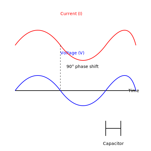
Capacitance, represented by the symbol C, measures the ability of a component to store electric charge per unit voltage. It is a fundamental property in capacitors and affects the component's filtering and energy storage capabilities.3. Power Dissipation (PD)
Power dissipation, denoted as PD, refers to the rate at which a component releases heat energy. It is a critical parameter in determining the thermal management requirements of electronic components to prevent overheating.4. ESR (Equivalent Series Resistance)
ESR is the sum of all resistances present in a capacitor's equivalent circuit. This parameter is crucial for assessing the efficiency and performance of capacitors, especially in high-frequency applications.5. Gain (HFE)
Gain, characterized by HFE in transistors, represents the amplification factor of the component. It quantifies the ratio of output current to input current, providing insights into the device's signal amplification capabilities.6. Frequency Response
Frequency response describes how a component's performance varies with input signal frequency. It is essential for evaluating the operational range and efficiency of components in different frequency domains.HTML code structure for code block2. Title and Introduction
2.2 Electrical Specifications
In electronic component datasheets, the electrical specifications provide crucial information about how the component behaves under various electrical conditions. Understanding these specifications is essential for selecting the right component for a specific application. Let's dive into some common electrical specifications found in datasheets: ###Operating Voltage
The operating voltage specifies the range of voltages over which the component can function correctly. It is crucial to ensure that the applied voltage does not exceed this range to prevent damage to the component. Operating voltage is particularly important for components such as integrated circuits and transistors. ###Current Handling Capacity
The current handling capacity indicates the maximum current that a component can safely carry without being damaged. For example, diodes and capacitors have specific current ratings that should not be exceeded to avoid failure. Understanding this specification is vital for designing circuits that operate within safe current limits. ###Power Dissipation
Power dissipation describes the amount of heat generated by a component when it is in operation. Components like resistors and transistors have power dissipation ratings that dictate the maximum heat they can withstand without overheating. Managing power dissipation is crucial for ensuring the reliability and longevity of electronic circuits. ###Frequency Response
The frequency response specifies how a component behaves at different frequencies. For components like capacitors and inductors, this specification details their impedance characteristics across a range of frequencies. Engineers must consider frequency response when designing circuits that operate at specific frequency ranges. ###Input and Output Impedance
Input and output impedance are critical specifications for components like amplifiers and sensors. Input impedance represents the resistance seen by the input signal, while output impedance indicates the resistance of the output signal path. Matching these impedances optimizes signal transfer and prevents signal degradation. ###Propagation Delay
Propagation delay is the time taken for a signal to travel through a component. This specification is crucial in applications where signal timing is critical, such as in digital circuits and communication systems. Minimizing propagation delay is essential for maintaining signal integrity and achieving reliable performance. Understanding and analyzing these electrical specifications in electronic component datasheets are essential for designing reliable and efficient electronic systems. By considering these parameters and selecting components that meet the required specifications, engineers can ensure the optimal performance of their circuits.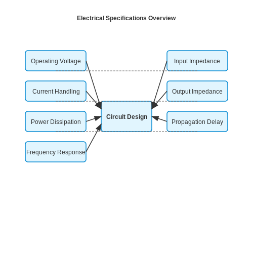
Mechanical Specifications
When designing electronic systems, understanding the mechanical specifications of components is crucial to ensure proper integration and functionality. Mechanical specifications provide detailed information about the physical characteristics and limitations of electronic components. These specifications encompass parameters such as size, shape, weight, mounting options, and environmental conditions under which the component can operate effectively. ### Importance of Mechanical Specifications Mechanical specifications play a vital role in determining how components can be incorporated into a system. They provide engineers with essential details for designing enclosures, selecting appropriate connectors, and ensuring compatibility with other mechanical elements within a product. Understanding these specifications is essential for ensuring durability, reliability, and optimal performance of electronic devices. ### Key Mechanical Specifications 1. Dimensions: The physical size of a component is typically specified in terms of length, width, and height. Understanding these dimensions is crucial for accommodating the component within the overall system design. 2. Mounting Options: Components may have different mounting options, such as through-hole mounting, surface mounting, or specific attachment mechanisms. Knowing these options is essential for proper installation and connection. 3. Operating Temperature Range: This specification indicates the range of temperatures within which the component can operate safely and reliably. It is crucial for determining the environmental conditions in which the component can function effectively. 4. Weight: The weight of a component is essential for structural design considerations, especially in portable devices where weight constraints are critical. 5. Environmental Protection: Some components have specifications related to environmental protection, such as resistance to moisture, dust, vibration, or specific hazards. Understanding these specifications is vital for applications in harsh or specialized environments. ### Practical Applications - Industrial Automation: Mechanical specifications are crucial in designing robust electronic systems for industrial automation, where components must withstand harsh conditions. - Aerospace and Defense: Components used in aerospace and defense applications require precise mechanical specifications to ensure reliability in extreme environments. - Consumer Electronics: Mechanical specifications influence the design and form factor of consumer electronic devices, impacting user experience and device aesthetics. ---2.4 Thermal Characteristics
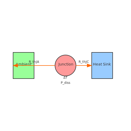
Thermal characteristics are crucial aspects of electronic components, especially in high-power applications or environments where temperature fluctuations play a significant role in performance. Understanding these characteristics is vital for designing reliable and efficient electronic systems. ## Thermal Resistance Thermal resistance (\(R_{\text{th}}\)) in electronic components is a key parameter that describes how resistant a component is to heat flow. It is defined as the temperature difference across the component divided by the power dissipated through it. Mathematically, it is represented as:
        # Sample Python code for thermal analysis
        def calculate_thermal_resistance(delta_T, dissipated_power):
            return delta_T / dissipated_power
2.5 Environmental Conditions
In electronic component datasheets, understanding the environmental conditions under which components can operate is crucial for ensuring their reliability and performance. Environmental conditions encompass factors such as temperature, humidity, pressure, and vibration that can significantly impact the behavior of electronic components. Let's delve into the key aspects of environmental considerations for electronic components. ##Temperature Considerations
Temperature plays a critical role in the performance and longevity of electronic components. Components are often rated for a specific temperature range within which they can operate reliably. The operating temperature range is typically specified as a minimum and maximum temperature. Exceeding these limits can lead to performance degradation or even component failure. Electronic components may also have different specifications for storage temperature, which indicates the acceptable temperature range when the component is not in operation. It is essential to adhere to these temperature specifications to ensure the proper functioning and longevity of electronic components. Practical applications of temperature considerations include designing circuitry for extreme environments such as aerospace or automotive systems where temperature variations are significant. ##Humidity and Moisture
Humidity and moisture can have detrimental effects on electronic components, especially those sensitive to moisture such as certain types of semiconductors. Datasheets often specify the maximum relative humidity level that components can withstand without compromising their performance. Moisture-sensitive components may also have special handling requirements to prevent moisture ingress during storage and assembly processes. Controlling humidity levels is crucial in applications where electronic components are exposed to high moisture environments, such as industrial control systems or outdoor installations. Proper encapsulation techniques and conformal coatings can be employed to protect components from moisture damage. ##Pressure and Vibration
In environments subject to mechanical stress, such as high-pressure or high-vibration settings, electronic components must be able to withstand these conditions without failure. Datasheets provide information on the maximum pressure and vibration levels that components can endure without performance degradation. Applications in industries like automotive, aerospace, and defense often require electronic components that are ruggedized to withstand high levels of vibration and pressure. Proper mounting techniques and shock-absorbing materials are used to ensure the reliability of components in such challenging environments. ##Combined Environmental Stress
In real-world scenarios, electronic components may be exposed to a combination of environmental stresses, such as high temperature and humidity or vibration and pressure. Understanding how components perform under these combined stress conditions is essential for designing robust and reliable electronic systems. Engineers and designers must consider the interplay between different environmental factors to ensure that components can operate effectively in diverse and sometimes harsh environments. Testing electronic components under simulated environmental stress conditions helps validate their performance and reliability in practical applications. By comprehensively evaluating and addressing environmental conditions in electronic component datasheets, engineers can make informed decisions regarding component selection, design considerations, and operational parameters to optimize system performance and reliability.3. Identifying Critical Parameters
3.1 Identifying Critical Parameters
To effectively understand and utilize electronic components, identifying their critical parameters is essential for engineers, physicists, researchers, and graduate students. Each component datasheet contains a wealth of technical information that can significantly impact the component's behavior in a circuit. Let's delve into the key aspects to focus on when analyzing electronic component datasheets.Understanding Operating Conditions
One of the primary sections in a datasheet is the operating conditions. Here, you can find details about the recommended voltage range, current ratings, temperature limits, and environmental considerations. Paying attention to these parameters ensures the component operates within its specified limits, guaranteeing reliability and performance.Electrical Characteristics
The electrical characteristics section provides crucial data on the component's behavior under different conditions. Parameters like capacitance, inductance, resistance, and frequency response define how the component interacts with the circuit. Understanding these characteristics helps in circuit design and performance optimization.Timing and Frequency Parameters
For components involving timing or frequency-dependent operations, datasheets include specifications like propagation delay, rise time, fall time, and maximum operating frequency. These parameters are critical in digital circuits, communication systems, and signal processing applications.Power Dissipation and Thermal Management
Power dissipation details the component's ability to handle and dissipate heat generated during operation. Thermal resistance, maximum junction temperature, and thermal impedance values guide proper thermal management in circuit designs, preventing overheating and component failure.Quality and Reliability Information
Datasheets often outline quality assurance measures, reliability ratings, and failure rate statistics. Understanding these aspects is crucial for mission-critical applications where component failure could have severe consequences. Components with higher reliability ratings are preferred for long-term and high-stress applications.Packaging and Mounting Specifications
Detailed information on the component's package type, dimensions, pin configuration, and recommended mounting techniques can be found in the datasheet. Proper handling and mounting are essential to ensure electrical performance, mechanical stability, and compliance with manufacturing standards.Environmental Compliance
Datasheets may include information on environmental compliance such as RoHS (Restriction of Hazardous Substances) and REACH (Registration, Evaluation, Authorization, and Restriction of Chemicals) directives. Understanding these regulations is crucial for ensuring the component meets industry standards for environmental sustainability. In conclusion, delving deep into electronic component datasheets and identifying critical parameters is fundamental for informed decision-making in circuit design, troubleshooting, and system optimization. By mastering the interpretation of datasheets, engineers and researchers can harness the full potential of electronic components in their applications.3.2 Understanding Operating Conditions
In electronic component datasheets, understanding the operating conditions is crucial for designing reliable and efficient circuits. The operating conditions define the range of parameters within which the component functions correctly and can help in optimizing performance.
Parameters to Consider:
1. Temperature Range
The temperature range specifies the minimum and maximum temperatures at which the component can operate effectively. Operating outside this range can lead to malfunctions or failures. It is vital to consider temperature effects on component characteristics like resistance, capacitance, and forward voltage.
2. Voltage Ratings
Understanding voltage ratings is essential to prevent damage to the component. This includes maximum operating voltage, breakdown voltage, and transient voltage ratings. Operating a component above its voltage ratings can cause irreparable damage.
3. Current Ratings
Current ratings determine the maximum current that a component can withstand without damage. Exceeding these ratings can lead to overheating, voltage drops, or even component failure. Proper consideration of current ratings ensures long-term reliability.
4. Power Dissipation
Power dissipation specifies how much heat the component can handle when operating at its maximum current and voltage ratings. Understanding power dissipation is crucial in thermal management to prevent overheating and maintain the component's integrity.
By carefully evaluating and adhering to the specified operating conditions in datasheets, engineers can design robust circuits that perform optimally under varying environmental conditions.
3.3 Analyzing Graphs and Tables
When delving into electronic component datasheets, understanding how to interpret the information presented in graphs and tables is crucial for advanced-level readers. Graphs and tables often convey key performance characteristics, specifications, and operating conditions of electronic components. This section will guide you through the process of systematically analyzing such data to extract valuable insights. Graphs in datasheets provide visual representations of electrical parameters such as voltage-current characteristics, frequency response, signal distortion, and more. Tables, on the other hand, offer concise numerical data on parameters like maximum ratings, thermal characteristics, and package dimensions. Together, these graphical and tabular representations offer a comprehensive view of a component's behavior under various conditions. Analyzing graphs involves carefully noting the axes, units, scaling, and data points. For instance, in a voltage-current curve of a diode, the forward voltage drop vs. current behavior can reveal important details like forward voltage at a specific current level or the dynamic resistance at different bias points. It is essential to pay attention to non-linearities, knee points, and areas of saturation to understand the component's behavior accurately. Tables in datasheets present quantitative data in a structured manner. These tables often list parameters such as operating temperature range, power dissipation ratings, input/output impedance, and more. Each entry in the table corresponds to a specific condition or characteristic of the component. By studying these tables meticulously, engineers can determine the operating limits of the component and select suitable operating conditions for their applications. In practical applications, analyzing graphs and tables helps engineers make informed decisions regarding component selection, circuit design, and performance optimization. By leveraging the information provided in datasheets, engineers can ensure that the chosen components meet the requirements of their systems, operate within safe limits, and deliver the expected performance. When interpreting graphs and tables, it is vital to consider the context of the data presented and correlate it with the application requirements. Whether designing a high-speed communication system, a power electronics converter, or an analog signal processing circuit, the insights gained from analyzing datasheet information play a pivotal role in achieving desired performance and reliability. Therefore, mastering the art of extracting valuable insights from graphs and tables in electronic component datasheets is a skill that distinguishes advanced-level engineers and researchers in the field of electronics. By combining theoretical knowledge with practical interpretation skills, professionals can unlock the full potential of electronic components and harness their capabilities to address complex engineering challenges effectively.Common Pitfalls in Reading Datasheets
When delving into electronic component datasheets, even the most advanced readers may encounter common pitfalls that can hinder accurate interpretation and implementation. Being aware of these issues is crucial for extracting the maximum benefit from datasheet information. Let's explore some of the key pitfalls to watch out for.
1. Lack of Standardization
Datasheets are not always standardized across manufacturers, leading to variations in the layout and key parameters provided. This lack of consistency can make comparison between components from different manufacturers challenging. Engineers must carefully analyze datasheets to ensure they are capturing the relevant information accurately.
2. Incomplete or Missing Information
Sometimes, datasheets may lack crucial details or omit specific operating conditions, performance characteristics, or limitations. This incomplete information can lead to design flaws or performance issues if not identified and addressed early in the design process. Engineers should cross-reference multiple sources if needed to fill in any missing data.
3. Overlooking Fine Print and Notes
Often, important details such as operating temperature ranges, derating factors, transient response characteristics, and application-specific notes are buried in the fine print or notes sections of a datasheet. Ignoring these details can result in component misuse, reliability issues, or even safety hazards. Careful attention to these sections is vital for a successful design.
4. Interpreting Graphs and Plots Incorrectly
Datasheets frequently include graphs and plots to represent various electrical characteristics. Engineers need to be cautious when interpreting these graphical representations and ensure they understand the scaling, units, and conditions under which the data was obtained. Misinterpreting these graphs can lead to incorrect design decisions.
5. Not Considering Application-Specific Requirements
While datasheets provide general specifications and performance metrics, they may not always account for the specific nuances of a given application or system. Engineers should critically evaluate component datasheets in the context of their unique design requirements, considering factors such as signal integrity, EMI susceptibility, and compatibility with other system components.
6. Relying Solely on Nominal Values
Datasheets often present nominal or typical values for parameters such as voltage, current, and frequency. However, variations in these parameters due to manufacturing tolerances or environmental factors can significantly impact performance. Engineers should look beyond nominal values and consider the worst-case scenarios to ensure robust design margins.
7. Neglecting Updates and Revisions
Electronic components undergo continuous refinement and improvement, leading to updates and revisions in datasheets over time. Ignoring these updates can result in using outdated information, which may no longer reflect the component's true capabilities or limitations. Engineers should regularly check for the latest datasheet versions to stay current with the most accurate information.
4. Resistors
4.2 Capacitors
Capacitors are fundamental electronic components that store electrical energy in an electrostatic field. They are widely used in electronic circuits for various purposes, including energy storage, filtering, timing, and coupling. ### Introduction to Capacitors Capacitors consist of two conducting plates separated by a dielectric material. When a voltage is applied across the plates, an electric field is created, causing the plates to store electric charge. The ability of a capacitor to store charge is quantified by its capacitance, measured in farads (F). Capacitance (\(C\)) is defined as the ratio of the charge stored on each plate (\(Q\)) to the voltage across the plates (\(V\)):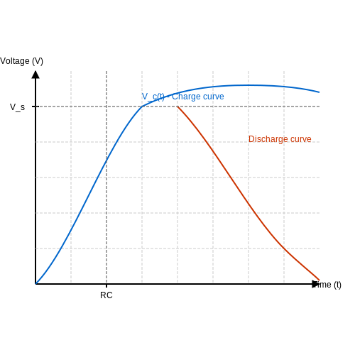
4.3 Transistors
Transistors are fundamental components in electronic circuits, serving various functions based on their type and design. Understanding transistor datasheets is crucial for engineers and researchers working on advanced electronics projects.
Types of Transistors
Transistors are broadly classified into bipolar junction transistors (BJTs) and field-effect transistors (FETs). BJTs are further categorized as NPN and PNP, while FETs include MOSFETs and JFETs.
Transistor Parameters
Key parameters in a transistor datasheet include:
- Maximum Voltage Ratings: VCEO, VCBO, VEB, VDS, etc.
- Maximum Current Ratings: IC, IB, ID, etc.
- Gain: hFE (BJTs), gm (FETs)
- Frequency Characteristics: fT, transition frequencies
Operating Regions
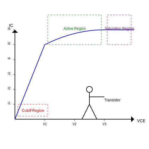
A transistor operates in three regions: cutoff, active, and saturation. Understanding these regions is crucial for designing and analyzing transistor circuits.
Biasing and Amplification
Biasing a transistor involves setting DC voltages and currents to establish the desired operating point. Transistors are commonly used for signal amplification in various electronic systems.
Applications in Electronics
Transistors find applications in amplifiers, oscillators, switches, and digital circuits. Understanding the characteristics detailed in datasheets is essential for optimizing circuit performance.
By mastering transistor datasheets and their associated parameters, engineers can design efficient and reliable electronic systems tailored to specific requirements.
4.4 Integrated Circuits
In the realm of electronic component datasheets, integrated circuits (ICs) play a crucial role due to their complexity and functionality. IC datasheets provide a wealth of information that engineers, physicists, researchers, and graduate students can analyze to understand the inner workings of these intricate devices.
Integrated circuits are miniaturized electronic circuits that contain numerous interconnected components such as resistors, capacitors, transistors, and diodes on a single semiconductor substrate. These components are fabricated using photolithography and other semiconductor manufacturing processes. Understanding IC datasheets is essential for designing, analyzing, and troubleshooting electronic circuits.
Understanding IC Datasheets
IC datasheets typically include a detailed description of the device, its pin configuration, electrical characteristics, absolute maximum ratings, recommended operating conditions, timing diagrams, functional diagrams, application circuits, and more. Let's delve into some key aspects:
Pin Configuration
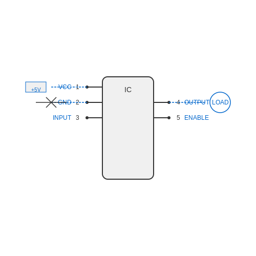
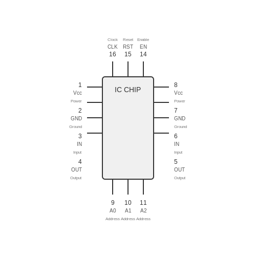
The pin configuration section of an IC datasheet illustrates the physical layout of the device's pins, their functions, and often their recommended connections on the circuit board. This information is crucial for correctly interfacing the IC with external components.
Electrical Characteristics
The electrical characteristics part details the operating parameters of the IC, including voltage supply range, input/output voltage levels, current consumption, operating temperature range, and more. Engineers use this data to ensure the IC operates within specifications.
Absolute Maximum Ratings
Absolute maximum ratings define the maximum voltage, current, power dissipation, and temperature limits beyond which the IC may be damaged. Operating the IC within these limits is vital to ensure device reliability and longevity.
Functional Diagrams
Functional diagrams depict the internal structure of the IC, showing how different blocks within the chip interact. These diagrams are instrumental in understanding the functionality and operation of the integrated circuit.
Application Circuits
Application circuits provide example schematics showing how to integrate the IC into various circuits or systems. Engineers often refer to these circuits when designing their applications to ensure proper functionality and performance.
By thoroughly analyzing the information presented in an IC datasheet, advanced-level readers can gain a profound understanding of the device's capabilities and limitations, enabling them to make informed decisions in their design or analysis activities.
5. Verifying Component Suitability
5.1 Verifying Component Suitability
In electronics, verifying the suitability of components is crucial for designing reliable circuits. Advanced-level readers such as engineers, physicists, researchers, and graduate students need to delve deeper into understanding how to assess electronic components for specific applications. ### Theoretical Considerations When examining electronic component datasheets for suitability, advanced readers should focus on comprehensive parameters such as voltage ratings, current capabilities, frequency response, temperature range, and tolerances. Understanding these specifications aids in selecting components that meet the operational requirements of a given circuit. ### Practical Relevance For engineers engaged in high-frequency circuit design, verifying component suitability involves analyzing characteristics like parasitic elements, impedance matching, and power handling capabilities. These considerations are essential for optimizing circuit performance in radio frequency (RF) or microwave applications. #### Mathematical Analysis To quantify component suitability, rigorous mathematical analysis is often required. Equations describing signal propagation, impedance transformation, power dissipation, and thermal management play a critical role in determining whether a component is suitable for a particular use case.- Electronics Tutorials — A comprehensive resource providing tutorials on electronics concepts and design guidelines.
- Analog Devices — Explore detailed datasheets and application notes for analog and mixed-signal components.
- Texas Instruments — Access a wide range of semiconductor products with detailed specifications and design resources.
- Keysight Technologies — Discover test and measurement solutions alongside in-depth technical articles on component evaluation.
- Mouser Electronics — Browse a vast catalog of electronic components with detailed descriptions and datasheets.
- Maxim Integrated — Learn about integrated circuits and sensor solutions through comprehensive datasheets and reference designs.
- ON Semiconductor — Access semiconductor solutions for power management, sensors, and signal processing with detailed specifications.
5.2 Cross-Referencing Data
In electronics, cross-referencing data from electronic component datasheets is a crucial skill for advanced-level readers like engineers, physicists, researchers, and graduate students. Understanding how to compare and analyze key parameters across different components can lead to optimized circuit designs and better performance. ## The Importance of Cross-Referencing Data Cross-referencing data allows engineers to validate specifications, compare performance metrics, and select the most suitable components for a given application. By examining datasheets side by side, one can gain insights into the trade-offs between different components and make informed decisions based on quantitative data. ## Practical Applications 1. Component Selection: Cross-referencing data helps in identifying suitable alternatives for a specific component based on performance, cost, or availability. 2. Performance Optimization: By comparing key parameters such as operating voltage, frequency response, and power dissipation, engineers can optimize circuit performance. 3. Reliability Analysis: Cross-referencing data aids in assessing the reliability of components by examining parameters like temperature ratings, MTBF (Mean Time Between Failures), and environmental specifications. ## Methodology for Cross-Referencing Data 1. Identify Key Parameters: Start by listing the critical parameters for your application, such as voltage, current, frequency, and temperature ratings. 2. Compare Datasheets: Obtain datasheets for different components and systematically compare the specified values for each parameter of interest. 3. Analyze Trade-offs: Evaluate trade-offs between parameters, such as power dissipation vs. frequency response or cost vs. performance, to make informed decisions. 4. Consider Application Requirements: Ensure that the selected component meets the specific needs of your circuit design, taking into account factors like environmental conditions and overall system constraints. ## Cross-Referencing Example Suppose you are designing a high-frequency amplifier and need to choose between two operational amplifiers. By cross-referencing the datasheets of both components, you can compare parameters like gain bandwidth product, input noise, and slew rate to determine the most suitable option for your application.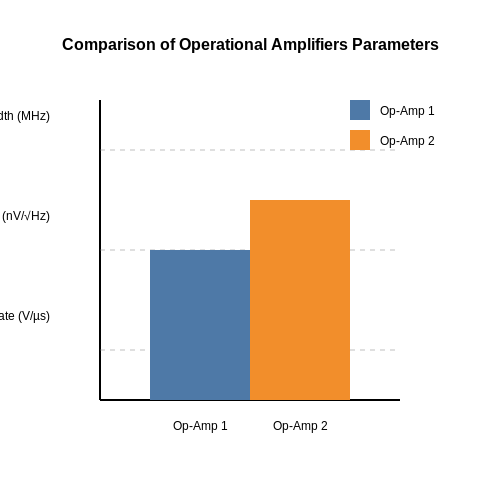
5.3 Keeping Updated with Manufacturer Changes
In the realm of electronic component datasheets, staying abreast of manufacturer changes is paramount for engineers, physicists, and researchers working with advanced technologies. Manufacturers frequently update specifications, performance characteristics, and recommended usage guidelines for their components. Failing to account for these changes could lead to design flaws, suboptimal performance, or even product failures. ## The Significance of Manufacturer Updates One key reason for closely monitoring manufacturer updates is the continuous advancement of technology. As manufacturers develop new materials, manufacturing processes, and design methodologies, these improvements often trickle down to their components. For instance, a resistor series may see efficiency enhancements or tolerance adjustments as a result of improved production techniques. ### Real-World Impact Consider a scenario where a company designs a high-performance amplifier using a specific operational amplifier (op-amp) model. If the op-amp manufacturer releases an updated version with improved noise characteristics or higher bandwidth, incorporating this new component could significantly enhance the amplifier's overall performance. ## Strategies for Tracking Changes To effectively track manufacturer changes, advanced-level professionals employ several strategies. One common approach involves subscribing to manufacturer newsletters, technical bulletins, or online forums where updates are announced. Additionally, establishing direct communication channels with manufacturer representatives can provide early access to upcoming revisions. ### Historical Context Historically, keeping track of component changes relied heavily on manual methods such as visiting manufacturer websites periodically or attending industry conferences for firsthand information. However, with the advent of digital platforms and automated notification systems, the process has become more streamlined and efficient. ## Practical Tips - Maintain a Datasheet Library: Create a centralized repository for datasheets and regularly update it with the latest versions. - Utilize RSS Feeds: Subscribe to manufacturer RSS feeds to receive instant notifications about new datasheets or product changes. - Attend Webinars and Seminars: Participate in virtual events hosted by manufacturers to gain insights into upcoming releases and modifications. By actively engaging with manufacturer updates and promptly integrating relevant changes into their projects, advanced-level professionals can ensure their designs are current, efficient, and in line with the latest industry standards. ---6. Key Texts on Electronic Components
6.1 Key Texts on Electronic Components
In the complex world of electronic engineering, understanding the finer details of component datasheets is crucial for any advanced practitioner. Datasheets provide critical insights into components and their specifications, enabling engineers, physicists, and researchers to make informed decisions during circuit design and analysis. This section delves into key sources that illuminate the intricacies of electronic components.
Understanding Datasheet Structure
Electronic component datasheets are comprehensive documents that detail the specifications and operational parameters of electronic parts such as resistors, capacitors, ICs, and transistors. To interpret these datasheets effectively, professionals must familiarize themselves with key terminologies and parameters mentioned. Typically, a datasheet includes information such as:
- Electrical Characteristics: This includes voltages, currents, power ratings, and tolerance levels. Understanding these characteristics helps ensure components operate safely and efficiently within a circuit.
- Mechanical Specifications: Datasheets outline the physical dimensions and package types, which is essential for proper fitting within a PCB design.
- Thermal Management: Information such as thermal resistance and maximum junction temperature is provided to prevent overheating and ensure long-term reliability.
Exploring Real-World Applications
Datasheets play a vital role in practical applications such as designing power supplies or amplifiers. For example, when selecting a transistor for a power amplifier, engineers rely on the datasheet to choose a component that can handle the necessary power levels and has the appropriate frequency response.
Similarly, in microcontroller applications, the datasheet specifies the pin configuration, power management features, and peripheral options which help engineers optimize the design for power efficiency and functionality.
The Importance of Precision in Data Interpretation
A thorough understanding of datasheet specifications allows for precision in selecting components that not only meet the technical requirements but also enhance the overall design efficiency. For instance, selecting a capacitor with a suitable Equivalent Series Resistance (ESR) can dramatically affect the performance of a switching power supply.
Conclusion
Grasping the contents of electronic component datasheets is an indispensable skill for advanced-level practitioners. These documents bridge the gap between theoretical knowledge and practical application, facilitating the design of robust and efficient electronic systems.
This section provides a detailed guide on interpreting electronic component datasheets, focusing on their structure, practical applications, and the precision needed for advanced design tasks. The information is tailored for an audience with a strong background in engineering and physics, offering insights into the critical role these datasheets play in the field of electronic design and analysis.6.2 Recommended Online Resources
In the advanced study and application of electronic components, datasheets are indispensable tools. They provide detailed specifications, operational parameters, and other critical information that engineers, physicists, and researchers rely on to optimize design and functionality. While datasheets traditionally come from manufacturers, an array of high-quality online resources now complements these documents. Below is a curated list of excellent online repositories and libraries providing access to electronic component datasheets. These platforms are specifically selected for advanced-level users seeking in-depth, reliable information.- Digi-Key Electronics Datasheets — Digi-Key Electronics offers a comprehensive database of electronic component datasheets. The site features user-friendly search options, allowing you to locate datasheets based on component specifications, manufacturer, and part number.
- Mouser Electronics Datasheet Search — With an intuitive interface, Mouser Electronics allows users to search its massive catalog for datasheets. It provides detailed component information that's crucial for making well-informed engineering decisions.
- Arrow Electronics Datasheets — Arrow Electronics provides an extensive selection of datasheets for various electronic components. The platform is renowned for its precise search capabilities and detailed specifications, serving as a vital tool for electronics professionals.
- RS Components DesignSpark — DesignSpark by RS Components is a high-quality resource for engineers and designers, offering free access to a broad range of electronic component datasheets essential for design and analysis processes.
- Octopart - Electronic Parts Search — Octopart is a powerful search engine for electronic components that aggregates datasheets, technical specifications, and distributor information into a single, easy-to-navigate platform.
- Component Search Engine — This platform connects users to billions of components, providing datasheets, CAD models, and lifecycle information, which is invaluable for component selection and comparison.
- Datasheets.com — Datasheets.com offers a fast and efficient way to download datasheets for millions of electronic parts from over 850 leading manufacturers, making it a significant resource in the electronics industry.
- Texas Instruments - Datasheets — As a leading semiconductor company, Texas Instruments provides access to their databases of datasheets, design resources, and application notes, crucial for the development of applications in diverse fields.
6.3 Industry Standard Publications
In the realm of electronics and electrical engineering, the importance of understanding the detailed specifications and characteristics of electronic components cannot be overstated. Industry-standard publications serve as the cornerstone for ensuring engineers and researchers are well-equipped with precise and definitive information about electronic components. These publications establish uniformity and reliability, providing crucial data used in design, testing, and implementation of electronic devices.
The Role of Organizations in Standardization
Various organizations are responsible for creating and maintaining documentation standards for electronic components. Their publications form an essential resource, reflecting decades of industry developments and global collaboration. Key organizations include:
- IEEE (Institute of Electrical and Electronics Engineers): Known for its extensive library of standards that cover a wide array of electrical and electronics topics, IEEE plays a critical role in standardizing electronic component datasheets.
- IEC (International Electrotechnical Commission): This organization develops international standards that facilitate cross-border trade and ensure quality and compatibility in the field of electronics.
- JEDEC (Joint Electron Device Engineering Council): Focused specifically on semiconductor devices, JEDEC standards are pivotal in shaping data sheet templates and ensuring consistency across various manufacturers.
- ISO (International Organization for Standardization): Although ISO covers a broad range of industries, its inputs provide fundamental frameworks for electronic component documentation.
The Importance of Standardization
Standardized datasheets enable a multitude of benefits:
- Interoperability: Ensures that components from different manufacturers can work together seamlessly.
- Quality Assurance: Provides a reliable reference that helps verify the performance characteristics of components.
- Cost Efficiency: Reduces the time spent by engineers in cross-referencing inconsistent datasheet information.
- Innovation: Establishes a baseline that facilitates the development of new technologies integrated with existing components.
Practical Applications and Cases
Consider the design of a high-frequency RF circuit. The stringent characteristics needed for component selection, like gain, noise figure, and bandwidth, are meticulously checked against standardized datasheets. For instance, in the aerospace industry, where every gram carries a cost, datasheets provide essential data allowing engineers to judiciously optimize weight-to-performance ratios, ensuring components like capacitors and semiconductor devices meet the strict mission parameters without redundant over-specification.
Moreover, with the rapid advancement in automotive technologies like electric vehicles, standards are continuously updated to reflect new electronic component requirements, ensuring vehicles are both safe and efficient.
Conclusion
As technology evolves, the role of industry-standard publications remains an enduring pillar in electronics. They not only streamline the processes of design and manufacture but also help cultivate a cohesive language that transcends geographical and cultural boundaries, ultimately inspiring a collaborative and innovative future.