Joule Heating in Conductors
1. Definition and Basic Principles
Joule Heating in Conductors: Definition and Basic Principles
Fundamental Mechanism
Joule heating, also known as ohmic or resistive heating, is the process by which electric energy is converted into thermal energy when an electric current passes through a conductor. This phenomenon arises due to collisions between charge carriers (typically electrons) and lattice ions in the conductor, resulting in energy dissipation as heat. The effect was first quantified experimentally by James Prescott Joule in 1841, establishing the relationship between current, resistance, and heat generation.
Mathematical Formulation
The power dissipation P due to Joule heating in a conductor can be derived from fundamental electromagnetic theory. Starting with the Lorentz force law and considering charge carrier drift velocity, we arrive at:
where J is the current density (A/m²) and E is the electric field (V/m). For a homogeneous conductor with constant current I and voltage drop V, this simplifies to:
Applying Ohm's Law (V = IR), we obtain the standard forms:
Microscopic Interpretation
At the atomic scale, Joule heating manifests through electron-phonon interactions. The mean free path λ of electrons determines the heating efficiency:
where τ is the relaxation time and vF is the Fermi velocity. Materials with shorter mean free paths (e.g., tungsten vs. copper) exhibit greater resistive heating due to more frequent electron scattering events.
Temperature Dependence
The resistivity ρ of most conductors varies with temperature according to:
where α is the temperature coefficient of resistivity. This creates a positive feedback loop in many applications - increased current leads to higher temperatures, which further increases resistance and heating.
Practical Considerations
In real-world systems, Joule heating must be carefully managed:
- Thermal runaway: Excessive heating can lead to insulation breakdown or conductor melting
- Material selection: High-temperature alloys (e.g., nichrome) are used in heating elements
- Cooling requirements: Power transmission lines require careful thermal design to prevent sagging
1.2 Historical Background and Discovery
The phenomenon of Joule heating, also known as ohmic heating or resistive heating, was first quantified by James Prescott Joule in 1841. His experiments demonstrated the direct relationship between electric current passing through a conductor and the heat generated, laying the foundation for the first law of thermodynamics and the principle of energy conservation.
Early Experiments and Observations
Joule's work built upon earlier observations by Humphry Davy, who in 1808 noted the incandescence of a platinum wire when an electric current was passed through it. However, Davy did not mathematically formalize the relationship between current, resistance, and heat. Joule's meticulous experiments involved measuring the temperature increase in water due to the mechanical work of a falling weight connected to a paddle wheel, and later, the heating effect of electric currents in wires.
where Q is the heat generated, I is the current, R is the resistance, and t is the time. This became known as Joule's first law.
Theoretical Development
Joule's findings were later integrated into the broader framework of thermodynamics by Hermann von Helmholtz and William Thomson (Lord Kelvin). The mathematical formulation was refined using Ohm's law (V = IR), leading to alternative expressions for Joule heating:
where P is the power dissipated as heat. This relationship became critical in the design of early electrical systems, where minimizing energy loss due to Joule heating was a key engineering challenge.
Practical Implications
The discovery of Joule heating had immediate practical applications, particularly in the development of incandescent lighting. Thomas Edison's carbon-filament lamps (1879) relied on Joule heating to produce light, though with low efficiency. Later, Nikola Tesla's work on alternating current systems highlighted the importance of reducing resistive losses in power transmission lines, leading to the adoption of high-voltage AC grids.
Modern applications of Joule heating span from household appliances (electric stoves, space heaters) to industrial processes (electric arc furnaces) and microfabrication (thermal annealing of semiconductors). The effect also poses challenges in high-power electronics, where excessive heating can degrade performance or cause device failure.
1.3 Mathematical Formulation (Joule's First Law)
The quantitative relationship governing Joule heating in conductors was first established experimentally by James Prescott Joule in 1841. The fundamental principle states that the heat energy (Q) dissipated per unit time in a conductor carrying current is proportional to the square of the current (I) and the resistance (R) of the conductor.
Derivation from Basic Principles
Beginning with the definition of electric power dissipation:
For an ohmic conductor, we substitute Ohm's Law (V = IR):
This gives the instantaneous power dissipation. The total energy converted to heat over time interval Δt is:
Where:
- Q = heat energy (Joules)
- I = current (Amperes)
- R = resistance (Ohms)
- Δt = time interval (seconds)
Microscopic Formulation
Expressed in terms of material properties and current density (J), the power density (p) is:
Where σ is conductivity. For a conductor of length L and cross-section A, this integrates to:
Practical Considerations
In AC circuits, the RMS current must be used for time-averaged power calculation:
For non-ohmic materials where resistance varies with temperature, the relationship becomes:
where R(T) follows the temperature coefficient relationship:
2. Role of Electrical Resistance
2.1 Role of Electrical Resistance
The power dissipated as heat in a conductor due to Joule heating is fundamentally governed by its electrical resistance. For a conductor with resistance R carrying current I, the instantaneous power dissipation P is given by:
This quadratic dependence on current highlights why high-current applications require careful thermal management. The resistance itself arises from microscopic scattering mechanisms, which can be quantified through the material's resistivity ρ:
where L is the conductor length and A its cross-sectional area. For most metallic conductors, ρ exhibits a positive temperature coefficient, leading to a nonlinear increase in Joule heating at elevated temperatures.
Temperature Dependence of Resistance
The resistivity of metals typically follows the Bloch-Grüneisen relation at temperatures above the Debye temperature:
where ρ0 is the residual resistivity (defect-dominated) and ρph(T) the phonon contribution. This temperature dependence creates a positive feedback loop in Joule heating: increased current → higher temperature → greater resistance → more heating.
Practical Implications
Three key engineering considerations emerge from this relationship:
- Current density limitations: Excessive current leads to thermal runaway in conductors
- Material selection: Copper/aluminum dominate power applications due to their low ρ values
- Geometric design: Thicker conductors reduce resistance but increase material costs
In high-power transmission lines, this manifests in the I2R losses that determine efficiency. For a 500 kV AC line carrying 2 kA through an aluminum conductor steel reinforced (ACSR) cable with R = 0.05 Ω/km, the power loss per kilometer would be:
Non-Ohmic Effects
At very high current densities (>108 A/m2 in copper), two additional phenomena become significant:
- Electron wind force: Momentum transfer from electrons can induce atomic migration (electromigration)
- Non-equilibrium heating: Electron and phonon systems may develop different effective temperatures
These effects are particularly critical in integrated circuit interconnects, where current densities routinely exceed 106 A/m2 and conductor dimensions approach the electron mean free path.
Energy Conversion Mechanism
Microscopic Origin of Joule Heating
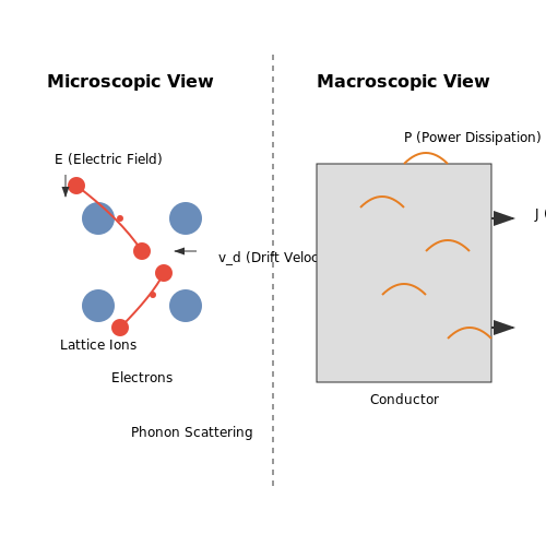
At the microscopic level, Joule heating arises from the interaction between conduction electrons and the lattice ions in a conductor. When an electric field E is applied, electrons accelerate, gaining kinetic energy. However, collisions with the lattice ions—primarily due to phonon scattering—dissipate this energy as heat. The average energy lost per collision is proportional to the square of the drift velocity vd, leading to the macroscopic observation of resistive heating.
Here, me is the electron mass. The drift velocity itself is related to the electric field via the mobility μ:
Macroscopic Power Dissipation
The power dissipated per unit volume Pv in a conductor can be derived from the work done by the electric field on the charge carriers. For a current density J flowing under an electric field E, the differential power is:
Substituting Ohm's law in its local form (J = σE, where σ is conductivity) and integrating over the volume yields the total dissipated power:
For a homogeneous conductor with constant cross-section A and length L, this simplifies to the familiar form:
where R = L/(σA) is the resistance. This confirms that the dissipated power scales quadratically with current, a hallmark of Joule heating.
Thermodynamic Considerations
From a thermodynamic perspective, Joule heating represents an irreversible conversion of electrical energy into thermal energy. The entropy production rate per unit volume is given by:
where T is the absolute temperature. This result follows directly from the Onsager relations for irreversible processes, highlighting the fundamental thermodynamic cost of resistive heating.
Practical Implications
In real-world applications, Joule heating must be carefully managed to prevent component failure. For example:
- High-power resistors are designed with large surface areas or cooling fins to enhance heat dissipation.
- Superconductors avoid Joule heating entirely by exhibiting zero resistance below their critical temperature.
- Integrated circuits face localized heating challenges, requiring advanced thermal management techniques such as heat sinks or liquid cooling.
Non-Ideal Effects
At high currents or frequencies, deviations from ideal Joule heating occur:
- Skin effect redistributes current density to the conductor surface, increasing effective resistance.
- Temperature-dependent resistivity modifies the heating dynamics, particularly in materials with strong thermal coefficients.
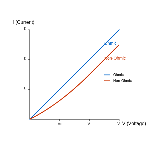
- Non-ohmic behavior in semiconductors or ionized gases leads to more complex current-voltage relationships.
These effects are critical in high-frequency transmission lines, power electronics, and plasma devices.
2.3 Temperature Dependence and Material Properties
The power dissipated as Joule heating in a conductor is given by:
However, the resistance R is not constant—it varies with temperature due to changes in the conductor's resistivity. For most metals, resistivity increases with temperature, leading to higher resistive losses at elevated operating conditions.
Temperature Coefficient of Resistance
The temperature dependence of resistivity for metallic conductors is well-approximated by:
where:
- ρ(T) is the resistivity at temperature T
- ρ0 is the reference resistivity at T0 (typically 20°C)
- α is the temperature coefficient of resistance (TCR)
The TCR quantifies how much the resistivity changes per degree of temperature variation. For pure metals like copper (α ≈ 0.0039/°C), even moderate heating can significantly impact resistance.
Derivation of Temperature-Dependent Resistance
Starting from the resistivity equation, we derive the conductor's resistance at temperature T:
This simplifies to:
where R0 is the reference resistance at T0. The temperature-dependent Joule heating power then becomes:
Material Selection Criteria
Key material properties affecting Joule heating include:
- Resistivity (ρ): Lower ρ reduces baseline heating (e.g., copper vs. nichrome)
- TCR (α): Materials with low α maintain stable resistance under thermal cycling
- Thermal conductivity: High conductivity helps dissipate generated heat
- Melting point: Critical for high-current applications
Comparison of Common Conductor Materials
| Material | ρ (20°C) [Ω·m] | α [1/°C] | Thermal Conductivity [W/m·K] |
|---|---|---|---|
| Copper | 1.68×10⁻⁸ | 0.0039 | 401 |
| Aluminum | 2.65×10⁻⁸ | 0.0043 | 237 |
| Tungsten | 5.60×10⁻⁸ | 0.0045 | 173 |
| Nichrome | 1.10×10⁻⁶ | 0.0004 | 11 |
Thermal Runaway Considerations
In systems with poor heat dissipation, the positive feedback between rising temperature and increasing resistance can lead to thermal runaway:
- Current flow increases conductor temperature
- Higher temperature increases resistance
- Increased resistance causes more Joule heating
- The cycle continues until failure occurs
This phenomenon is particularly critical in:
- Power transmission lines during fault conditions
- Semiconductor devices operating near maximum ratings
- Precision resistors in measurement circuits
Practical Mitigation Strategies
Engineers employ several approaches to manage temperature-dependent Joule heating:
- Material selection: Using alloys with low TCR (e.g., manganin) for stable resistance
- Cooling systems: Forced air/liquid cooling for high-power applications
- Derating curves: Reducing maximum current at elevated ambient temperatures
- Thermal fuses: Circuit protection devices that open at critical temperatures
3. Heating Elements in Appliances
3.1 Heating Elements in Appliances
Fundamentals of Joule Heating in Resistive Loads
The power dissipation P due to Joule heating in a conductor is governed by the relation:
where I is the current and R is the resistance. In heating elements, this energy is converted directly into thermal energy, raising the temperature of the conductor. The temperature rise ΔT can be approximated by:
where t is time, m is the mass of the conductor, and cp is the specific heat capacity.
Material Selection for Heating Elements
Optimal materials for heating elements must satisfy several criteria:
- High resistivity to maximize power dissipation per unit length
- High melting point to withstand operational temperatures
- Oxidation resistance to prevent degradation in air
- Mechanical stability at elevated temperatures
Common materials include nichrome (80% Ni, 20% Cr), kanthal (Fe-Cr-Al), and molybdenum disilicide (MoSi2). The temperature coefficient of resistance α must be considered in design:
Design Considerations for Appliance Heating Elements
The geometry of heating elements is critical for performance:
- Wire diameter affects current density and maximum temperature
- Coil pitch influences heat distribution and convection
- Surface area determines heat transfer rate to surroundings
For a given power requirement P, the required resistance can be calculated from:
where V is the operating voltage. The length L of wire needed is then:
where A is the cross-sectional area and ρ is the material resistivity.
Thermal Management and Efficiency
The steady-state temperature of a heating element is determined by the balance between electrical power input and thermal losses:
where the terms represent radiative, convective, and conductive heat transfer respectively. Radiative loss follows the Stefan-Boltzmann law:
with ε as emissivity and σ the Stefan-Boltzmann constant.
Practical Applications and Case Studies
Modern appliances employ various heating element configurations:
- Open-coil elements in toasters and space heaters
- Sheathed elements in electric stoves and water heaters
- Thick-film elements in precision industrial equipment
The choice depends on required temperature range, power density, and environmental conditions. For example, sheathed elements in water heaters use MgO insulation to prevent electrical contact with water while maintaining high thermal conductivity.
3.2 Industrial Processes (e.g., Welding, Melting)
Joule heating plays a critical role in industrial applications where controlled thermal energy is required for material processing. The principle of resistive heating is exploited in processes such as welding, metal melting, and heat treatment, where high currents are passed through conductive materials to generate localized or bulk heating.
Resistance Welding
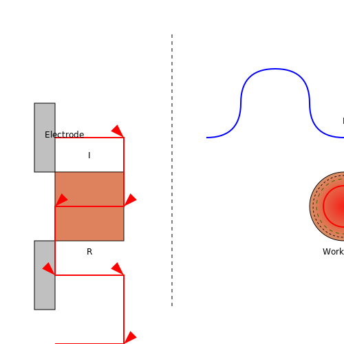
Resistance welding relies on Joule heating to join metal workpieces. When a high current (typically thousands of amperes) is forced through the contact resistance between two metals, the generated heat softens or melts the material, forming a weld upon cooling. The power dissipated is given by:
where I is the current, R is the contact resistance, and t is the time duration. Spot welding, seam welding, and projection welding are common variants, each optimizing current density and pressure to achieve consistent welds.
Electric Arc Welding
In arc welding, Joule heating occurs not only in the electrode and workpiece but also in the plasma arc formed between them. The total heat input Q is derived from:
where η is the process efficiency (typically 0.7–0.85 for shielded metal arc welding), V is the arc voltage, and I is the welding current. The intense heat (up to 20,000°C in plasma arcs) melts the base metals and filler material, enabling deep penetration welds.
Induction and Direct Resistance Melting
Industrial melting furnaces utilize Joule heating in two primary configurations:
- Direct resistance melting: Current is passed directly through the charge material (e.g., graphite electrodes in submerged arc furnaces for steel production). The power density follows:
where ρ is the material resistivity and L is the electrode spacing.
- Induction melting: Eddy currents induced in conductive materials by alternating magnetic fields generate heat through I²R losses. The skin depth δ governs heat penetration:
where μr is relative permeability and f is frequency. Higher frequencies (1–10 kHz) enable precise surface heating, while lower frequencies (50–60 Hz) provide bulk heating for large-scale smelting.
Thermal Design Considerations
Industrial systems must account for:
- Thermal runaway due to positive temperature coefficients in some materials
- Electrode degradation at high temperatures (e.g., tungsten erosion in TIG welding)
- Cooling requirements for high-duty cycle operations
- Energy efficiency optimization through pulse-width modulation in modern power supplies
Advanced control systems now integrate real-time thermal imaging with adaptive current regulation to maintain optimal processing temperatures while minimizing energy waste.
Safety Considerations and Thermal Management
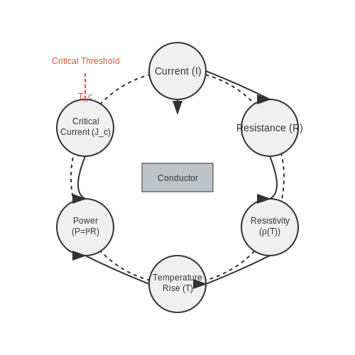
Thermal Runaway and Critical Current Density
Joule heating in conductors follows the power dissipation law:
where P is power dissipation, I is current, and R is resistance. As temperature rises, the conductor's resistivity (ρ) increases, further amplifying power dissipation—a positive feedback loop known as thermal runaway. The critical current density (Jc) defines the maximum sustainable current before runaway occurs:
Here, k is thermal conductivity, Tc is the critical temperature, T0 is ambient temperature, ρ0 is baseline resistivity, α is the temperature coefficient of resistance, and L is conductor length.
Material Selection and Derating
Copper and aluminum are common conductors, but their thermal limits differ. Copper’s melting point (1085°C) exceeds aluminum’s (660°C), but both require derating—reducing operational current below theoretical limits—to account for:
- Insulation ratings: PVC (105°C) vs. PTFE (260°C)
- Ambient conditions: Airflow, enclosure design, and adjacent heat sources
- Transient loads: Inrush currents or pulsed operation
The International Electrotechnical Commission (IEC) 60287 standard provides derating curves for cables under varying thermal environments.
Active and Passive Cooling Strategies
Passive Cooling
Heat sinks and thermal vias exploit conduction and convection. The thermal resistance (θth) of a heat sink is:
where Tj is junction temperature and Ta is ambient temperature. Aluminum finned heat sinks with θth < 5°C/W are typical for high-current PCBs.
Active Cooling
Forced air or liquid cooling becomes necessary when passive methods exceed limits. The Nusselt number (Nu) predicts convective efficiency:
where h is heat transfer coefficient and Lc is characteristic length. Active systems reduce θth by 50–80% but introduce complexity and failure modes (e.g., fan wear).
Fusing and Circuit Protection
Fast-acting fuses leverage Joule heating intentionally. The melting integral (I2t) quantifies energy required to melt the fuse element:
where K is a material constant and A is cross-sectional area. Semiconductor fuses (e.g., IEC 60269) protect power electronics by clearing faults within 10 ms.
Case Study: High-Power Busbars
In substations, aluminum busbars (5000 A/mm2) use black anodization to enhance emissivity (ε ≈ 0.85) and radiative cooling. Temperature rise is modeled via the Holman equation:
where σ is Stefan-Boltzmann constant (5.67×10⁻⁸ W/m2K4). Forced-air cooling maintains ΔT < 40°C at 5 kA loads.
4. Power Dissipation in Conductors
4.1 Power Dissipation in Conductors
When an electric current I flows through a conductor with resistance R, energy is dissipated as heat due to electron collisions with lattice ions. This phenomenon, known as Joule heating, results in power dissipation given by:
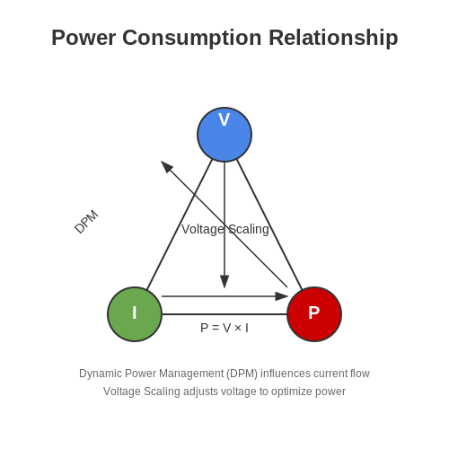
This relationship arises directly from Ohm's Law (V = IR) and the definition of electric power (P = VI). Substituting Ohm's Law into the power expression yields:
Alternatively, if voltage is known instead of current, the power dissipation can be expressed as:
Microscopic Interpretation
At the microscopic level, power dissipation per unit volume (p) in a conductor is derived from the current density J and electric field E:
For an isotropic conductor obeying Ohm's Law (J = σE), where σ is conductivity, this reduces to:
Integrating over the conductor's volume yields the total dissipated power, consistent with the macroscopic expression P = I²R.
Thermal Implications
The dissipated power manifests as heat, raising the conductor's temperature until thermal equilibrium is reached. The steady-state temperature T depends on:
- Power dissipation (P)
- Thermal resistance (Rth) of the conductor-environment system
- Ambient temperature (Ta)
Expressed mathematically:
Exceeding critical temperatures can degrade insulation, alter material properties, or cause failure—making thermal management essential in high-current applications.
Practical Considerations
In real conductors, resistance varies with temperature due to changes in resistivity (ρ):
where α is the temperature coefficient of resistance. This creates a feedback loop: higher current → more heating → increased resistance → further power dissipation. Designers must account for this in:
- Power transmission lines: Minimizing I²R losses by using high-voltage, low-current configurations.
- Electronic components: Derating power ratings to prevent thermal runaway.
- Fuses: Exploiting Joule heating to melt conductors at predetermined currents.
For alternating current (AC), the root-mean-square (RMS) current determines the average power dissipation:
Skin effect further complicates AC scenarios by confining current to conductor surfaces, effectively increasing resistance at high frequencies.
4.2 Heat Generation Rate and Efficiency
The rate of heat generation in a conductor due to Joule heating is governed by the power dissipation equation. For a conductor carrying a steady current I with resistance R, the instantaneous power dissipated as heat is given by:
This relationship arises directly from Ohm's Law (V = IR) and the definition of electrical power (P = VI). Substituting Ohm's Law into the power equation yields the two equivalent forms:
In time-dependent systems where current varies, the total energy E dissipated over a time interval Δt is obtained by integrating the power:
Thermal Efficiency Considerations
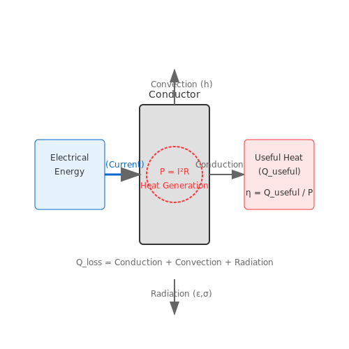
In practical applications, not all electrical energy converts into useful heat. The efficiency η of a Joule heating system accounts for losses due to:
- Thermal conduction away from the target region
- Radiation losses to the environment
- Convective cooling by surrounding fluids
The net useful heat output Quseful relates to the electrical input power by:
where η typically ranges from 0.7 to 0.95 for well-designed systems. For resistive heating elements, manufacturers often specify the thermal efficiency under standard operating conditions.
Temperature Dynamics
The steady-state temperature T of a conductor under Joule heating balances heat generation with heat loss mechanisms. For a uniform conductor in still air, Newton's Law of Cooling gives:
where h is the convective heat transfer coefficient, A the surface area, T∞ the ambient temperature, ε the emissivity, and σ the Stefan-Boltzmann constant. At moderate temperatures (<150°C), radiation often contributes less than 10% of total heat loss.
Material Selection Criteria
Optimal materials for resistive heating applications exhibit:
- High resistivity to maximize heat generation per unit length
- Positive temperature coefficient of resistance for self-regulation
- High melting point for wide operating range
- Good oxidation resistance at elevated temperatures
Common choices include nichrome (80% Ni, 20% Cr) with ρ ≈ 1.1 × 10⁻⁶ Ω·m and Kanthal (FeCrAl alloy) with ρ ≈ 1.4 × 10⁻⁶ Ω·m. For high-temperature applications, molybdenum disilicide (MoSi2) offers stability up to 1800°C.
Transient Analysis
The temperature evolution follows the heat equation with Joule heating as a source term:
where ρ is material density, cp specific heat capacity, k thermal conductivity, and ρe electrical resistivity. For a thin wire with diameter d, the characteristic thermal time constant is:
This determines how quickly the system reaches thermal equilibrium after power application.
4.3 Case Studies and Real-World Examples
High-Power Transmission Lines
Joule heating is a critical consideration in high-voltage power transmission lines. The power dissipated as heat in a conductor is given by:
where I is the current and R is the resistance of the conductor. For a typical aluminum conductor steel-reinforced (ACSR) cable with a resistance of 0.1 Ω/km carrying 1000 A, the power loss per kilometer is:
This heat dissipation necessitates careful thermal management, including proper spacing between conductors and the use of high-temperature materials to prevent sagging due to thermal expansion.
Microprocessor Interconnects
In modern integrated circuits, Joule heating in nanoscale copper interconnects poses significant reliability challenges. The current density in these interconnects can exceed 106 A/cm2, leading to localized heating. The temperature rise can be approximated by:
where Rth is the thermal resistance, R is the electrical resistance, and A is the cross-sectional area. For a 100 nm wide interconnect with Rth = 105 K/W and R = 100 Ω, a current of 1 mA produces:
This temperature rise can accelerate electromigration, leading to premature failure of the interconnect.
Electric Vehicle Battery Systems
Joule heating in battery packs affects both performance and safety. The heat generation rate in a battery cell is:
where Rint is the internal resistance and V is the cell voltage. For a lithium-ion cell with Rint = 50 mΩ discharging at 100 A, the resistive heating component alone is:
This heat must be effectively managed through liquid cooling or phase-change materials to maintain optimal battery temperature (typically 20-40°C).
Superconducting Fault Current Limiters
These devices exploit the abrupt transition from superconducting to normal state when current exceeds a critical value. The joule heating during the normal state is given by:
where ρ is the normal-state resistivity, Jc is the critical current density, V is the volume, and Tc is the critical temperature. For a YBCO tape with Jc = 104 A/cm2 and Tc = 92 K operating at 77 K, the power density reaches:
This intense localized heating requires careful thermal engineering to prevent damage to the superconductor.
Electrosurgical Instruments
Joule heating is intentionally utilized in electrosurgical tools where high-frequency currents (typically 300 kHz to 3 MHz) pass through tissue. The power deposition is:
where σ is the tissue conductivity and r is the electrode radius. For a 1 mm diameter electrode delivering 1 A to tissue with σ = 0.3 S/m, the power density at the electrode surface is:
This controlled heating enables precise tissue cutting while minimizing collateral damage.
5. Key Research Papers and Books
5.1 Key Research Papers and Books
- Joule Heating and Arc-Fault-Induced Electrical Fires for ... - MDPI — Feature papers represent the most advanced research with significant potential for high impact in the field. ... Electronic and Automation, Xi'an, China, 24-26 September 2021; pp. 248-252. ... "Joule Heating and Arc-Fault-Induced Electrical Fires for Commercial-Grade Copper and Brass in Low-Voltage Electrical Systems" Applied Sciences 12 ...
- Progress in Flexible Electronic Textile for Heating Application: A ... — The power supply, flexible heating device, clothing, safety protection elements, and temperature control module are key elements of composing conductive heating textiles. Joule's heating principle describes the heat generation; the power of heating ( P ) is related to the resistance ( R ) and electric current ( I ) of the conductor and is ...
- Advancements in electrothermal heterogeneous catalytic pollutants ... — Electrothermal catalysis is a type of electrical heating technique that occurs through Joule heating (also known as Ohmic heating, resistive heating, or conductive heating). It is distinguished from other external electrical heating methods such as microwave, plasma, and electromagnetic induction by the contact between electrodes and the ...
- MHD Convection with Joule Heating and Internal Heat Generation in a Two ... — Joule heating occurs in a fluid due to its electrical resistance. When a magnetic field is introduced, it induces an electric current within the fluid, which then encounters resistance, producing heat. ... The principal objective of the current research is to elevate heat transfer effectiveness by identifying optimal system characteristics and ...
- Toward Joule heating recycling of spent lithium-ion batteries: A rising ... — In Joule heating technology, an electric current passes through an electrically conductive powder or film, the heat is generated due to the existence of resistance as internally. ... λ, T = γ ε g r a y 2 h c 2 λ 5 1 e hc / ... National Ten Thousand Talents Program, national key research and development project, and other projects. He has ...
- Three‐dimensional finite‐element analysis multiphysics modelling of ... — The source coil designs and, in particular, the current control in the Joule heating unit was key to ensuring the same current was applied as in the Biot-Savart conductor in the 3D FE models. The output current to the source coil in the test-rig was also monitored experimentally using a high-frequency current probe (as illustrated in Fig. 17 ).
- Solved with COMSOL Multiphysics 5.1 Joule Heating of a Microactuator — Academia.edu is a platform for academics to share research papers. Solved with COMSOL Multiphysics 5.1 Joule Heating of a Microactuator . × ... Property Name Value Unit Electrical conductivity sigma 5e4 S/m Basic Relative permittivity epsilonr 4.5 1 Basic Thermal conductivity k 40 W/(m·K) Basic Density rho 2.3e3 kg/m³ Basic Cp 600 J/(kg·K ...
- Multi-physics electrical contact analysis considering the electrical ... — The Joule heating from the interfacial electrical resistance is treated as a surface heat flux according to Eq. (4), and the Joule heating of the constriction resistance is a body heat source, which can be calculated easily in the FEM model by the product of the current density and the electric field strength (Tian et al., 2020). The FEM ...
- Numerical Algorithms for Calculating Temperature, Layered Stress, and ... — As the critical temperature and current are related to layered stress and temperature field of conductors, the following factors are assumed to be sensitive: (1) solar intensity S with a unit of W/m 2 and range of 0∼1000; (2) solar absorption α s, dimensionless, with a range of 0.23∼0.9, reflecting the age of the conductors; new bright ...
- (PDF) Joule's law for organic transistors exploration ... - ResearchGate — Note that the variation in E a can be large from device to device, and the Joule's heating at contacts can be significant especially in the saturation regime for the higher current density.
5.2 Online Resources and Tutorials
- Progress in Flexible Electronic Textile for Heating Application: A ... — The power supply, flexible heating device, clothing, safety protection elements, and temperature control module are key elements of composing conductive heating textiles. Joule's heating principle describes the heat generation; the power of heating (P) is related to the resistance (R) and electric current (I) of the conductor and is ...
- Accelerated Curing and Enhanced Material Properties of Conductive ... — Joule heating is useful for fast and reliable manufacturing of conductive composite materials. In this study, we investigated the influence of Joule heating on curing conditions and material properties of polymer-based conductive composite materials consisting of carbon nanotubes (CNTs) and polydimethylsiloxane (PDMS). We applied different voltages to the CNT nanocomposites to investigate ...
- Three‐dimensional finite‐element analysis multiphysics modelling of ... — The possibility of using single-sided Joule heating (as illustrated in Fig. 5 b) was therefore also investigated, since single-sided source coil Joule heating is a greater challenge in producing the required heat in a CFC compared to double-sided but is nonetheless still required.
- IB DP Physics Topic 5. Electricity and magnetism: 5.2 Heating effect of ... — For a current to flow through a cross-section, there must be a net flow of charge through that cross-section. In a metal like copper there are around 10 28 free electrons per m 3 moving randomly in all direction with speeds of the order of 10 6 m/s even in the absence of electric field. But since the number of electrons passing through a cross-section from left to right is equal to the number ...
- Multi-physics electrical contact analysis considering the electrical ... — The Joule heating from the interfacial electrical resistance is treated as a surface heat flux according to Eq. (4), and the Joule heating of the constriction resistance is a body heat source, which can be calculated easily in the FEM model by the product of the current density and the electric field strength (Tian et al., 2020). The FEM ...
- PDF E X P E R I M E N T 5 - Collin — resistor (in joules) to the energy gained by the water in (calories), you will determine the electric equivalent of heat. W = J H Equation 5.8 or J = W/H = 4.186 joules/cal Equation 5.9 The electric equivalent of heat has the same value as the mechanical equivalent of heat, i.e., 1 cal = 4.186 joules.
- PDF 'Modular Electronics Learning (ModEL) project' - The Public's Library ... — Writing an outline to summarize your own understanding of the text (tutorial) is a highly effective way to maximize your reading comprehension. An idea for your outline is to list all versions of the Ohm's Law equation and also the Joule's Law equation. It is important to be able to derive all
- Joule Heating and Arc-Fault-Induced Electrical Fires for ... - MDPI — Electrical fires are usually caused by contact heating, for which the mechanism of heat accumulation is currently not well understood. Previous studies done by many researchers were able to recognize the pattern of the electrical waveform, but the actual mechanism behind such phenomenon is still a mystery. This research focuses on electrical plugs and sockets made from copper and electrical ...
- 3.2 Ohm's Law, Joules Law, and Series/Parallel Formulas — 3.2 Ohm's Law, Joules Law, and Series/Parallel Formulas Ohm's Law. The current that flows through most substances is directly proportional to the voltage V applied to it. The German physicist Georg Simon Ohm (1787-1854) was the first to demonstrate experimentally that the current in a metal wire is directly proportional to the voltage applied: I ∝ V.
-
PDF Chapter 10: Superconductivity — Figure 1: The speci c heat of a superconductor C S and and normal metal C n. Below the transition, the superconductor speci c heat shows activated behavior, as if there is a minimum energy for thermal excitations. the activated nature of C for T
5.3 Advanced Topics and Related Studies
- Three-dimensional finite-element analysis multiphysics modelling of ... — This study investigates the possibility of electromagnetic heating of carbon fibre composites (CFCs) to the resin curing temperature, utilising Joule heating, with the main potential application being the on-site and in-situ repair of damaged CFCs. The study describes the energy conversion from the supplied AC electrical current to the power generated and hence, heat produced in a CFC. This is ...
- Advancements in electrothermal heterogeneous catalytic pollutants ... — The injection and movement of electrons convert electronic energy into thermal energy through various processes, including electron-phonon coupling, Joule heating, and energy transfer from electron excitation. These mechanisms work in concert to increase the catalyst's temperature, thereby enhancing the reaction's activity and selectivity.
- PDF initialpages.PDF - Stanford University — The simulation methodology has also been applied to quantify the use of dummy thermal vias as addi- tional heat sinking paths and possible solution to hot wires. The impact of Joule heating on the scaling trends of advanced VLSI interconnects has been evaluated in detail. It shows the interconnect Joule heating can strongly affect
- Synthesis of PEDOT:PSS Solution-Processed Electronic Textiles for ... — Textile-based flexible and wearable electronic devices provide an excellent solution to thermal management systems, thermal therapy, and deicing applications through the Joule heating approach. However, challenges persist in designing such cost-effective electronic devices for efficient heating performance. Herein, this study adopted a facile solution-processed strategy, "dip-coating", to ...
- 11 - Joule heating and its role in current-assisted domain wall ... — A large current density generates heat, a fact that often has detrimental consequences for the operation of the device or even for the interpretation of scientific results. From the experimental point of view, having an idea of how relevant the Joule heating may be in your nano-device can save time and trouble.
- Joule Heating and Arc-Fault-Induced Electrical Fires for ... - MDPI — The two electrical conductors must have a poor contact spot so as to increase contact resistance [19] and Sharvin resistance, thus creating the Joule heating effect.
- Progress in Flexible Electronic Textile for Heating Application: A ... — Joule's heating principle describes the heat generation; the power of heating (P) is related to the resistance (R) and electric current (I) of the conductor and is calculated by Equation (1).
- Joule heating flow control methods for high-speed flows — Joule heating is the generation of heat by the passage of current through a conductor. This is a review of a group of flow control methods that employ Joule heating to do so and can collectively be called energy deposition flow control methods.
- Joule-Heated Catalytic Reactors toward Decarbonization and Process ... — Joule heating, also known as resistive or ohmic heating, is a process in which the electric energy is transformed into thermal energy when an electric current flows across an electrical conductor.
- Numerical Algorithms for Calculating Temperature, Layered Stress, and ... — Based on 2D steady-state heat transfer equations, this article studies the temperature fields of the cross section of typical electrified conductors and establishes numerical simulation methods for calculating the layered stress, sag, and critical temperature.