Transformer Construction
1. Magnetic Core Materials and Types
1.1 Magnetic Core Materials and Types
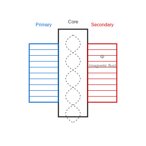
The magnetic core of a transformer serves as the medium for flux linkage between primary and secondary windings, directly influencing efficiency, saturation behavior, and losses. Core material selection is governed by parameters such as permeability, saturation flux density, hysteresis loss, and eddy current loss.
Key Material Properties
The performance of a magnetic core is determined by:
- Relative permeability (μr): Dictates how easily the material magnetizes. High-μr materials (e.g., ferrites) reduce magnetizing current but may saturate earlier.
- Saturation flux density (Bsat): The maximum magnetic flux the core can sustain before nonlinearity occurs. Silicon steel offers Bsat ≈ 2 T, while ferrites saturate near 0.5 T.
- Core loss (Pcore): Comprises hysteresis loss (Ph) and eddy current loss (Pe), quantified by Steinmetz’s equation:
where \(P_v\) is the volumetric loss density, \(k_h\) and \(k_e\) are material constants, \(f\) is frequency, and \(\alpha\) (1.6–2.0) is the Steinmetz exponent.
Common Core Materials
1. Grain-Oriented Silicon Steel (GOES)
Cold-rolled steel with 3% silicon, exhibiting anisotropic permeability. The grain alignment reduces hysteresis loss, making it ideal for 50/60 Hz power transformers. Typical thicknesses range from 0.23 mm to 0.35 mm, with laminations insulated to mitigate eddy currents.
2. Amorphous Metal (Metglas)
Alloys like Fe80B20 lack crystalline structure, yielding near-zero hysteresis loss. Used in high-efficiency transformers, but their brittleness complicates manufacturing. Saturation flux density is ≈1.6 T.
3. Ferrites (Mn-Zn, Ni-Zn)
Ceramic oxides with high resistivity (102–106 Ω·m), minimizing eddy currents at high frequencies (kHz–MHz). Mn-Zn ferrites dominate in SMPS applications due to their high μr (2000–15000), while Ni-Zn suits RF transformers.
4. Powdered Iron
Insulated iron particles compressed into cores, trading permeability for distributed air gaps. Used in inductors where saturation resilience outweighs efficiency concerns.
Core Geometries
Material choice often dictates core shape:
- EI laminations: Stacked silicon steel sheets for low-frequency power transformers.
- Toroidal cores: Wound strip or ferrite, minimizing flux leakage and EMI.
- Planar cores: Ferrite plates with printed windings for high-power-density applications.
Practical Tradeoffs
High-frequency designs (≥100 kHz) prioritize low core loss, favoring ferrites or amorphous metals. Low-frequency applications leverage GOES for its cost-effective Bsat. For variable loads, powdered iron’s linearity may be preferable despite lower μr.
where \(A_e\) is the effective cross-sectional area, and \(N\) is the turns count. This equation guides core sizing to avoid saturation.
Primary and Secondary Windings
The primary and secondary windings are the fundamental conductive pathways in a transformer, responsible for electromagnetic induction and energy transfer. Their design directly impacts efficiency, voltage transformation ratio, and thermal performance.
Winding Configurations
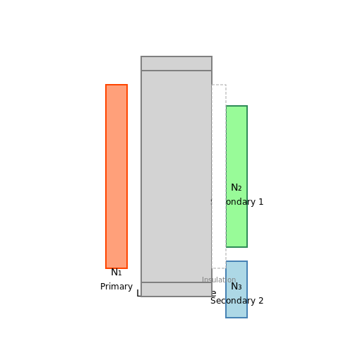
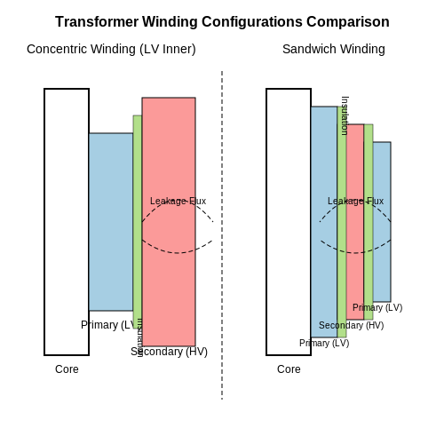
Transformers employ either concentric or sandwich (interleaved) winding arrangements. In concentric windings, the primary and secondary coils are wound concentrically around the core, with the low-voltage (LV) winding typically placed closer to the core to minimize insulation requirements. Sandwich windings alternate primary and secondary layers, reducing leakage inductance but increasing interwinding capacitance.
Electrical Characteristics
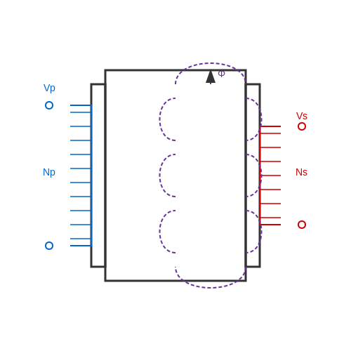
The voltage transformation ratio K is determined by the turns ratio between primary (Np) and secondary (Ns) windings:
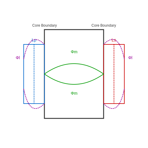
Leakage inductance (Lleak) arises due to imperfect magnetic coupling and is modeled as:
where k is the coupling coefficient, A is the cross-sectional area, and l is the magnetic path length.
Materials and Construction
- Conductors: High-purity copper or aluminum, with rectangular or round cross-sections for optimal space factor.
- Insulation: Class A (105°C) to Class H (180°C) materials, including Nomex, polyester films, or epoxy coatings.
- Stranding: Litz wire for high-frequency applications to mitigate skin and proximity effects.
Practical Design Considerations
Winding resistance (Rac) must account for AC effects at operating frequencies:
where d is conductor thickness and δ is skin depth. For power transformers, interleaved disk windings with 0.3–0.6 mm pressboard barriers between layers optimize dielectric strength and cooling.
High-Frequency Transformers
In switch-mode power supplies, planar windings using PCB traces or foil conductors minimize parasitic capacitance. The interwinding capacitance (Cw) is critical:
where d is the separation distance and εr is the relative permittivity of the insulating material.
1.3 Insulation and Cooling Systems
Insulation Materials and Techniques
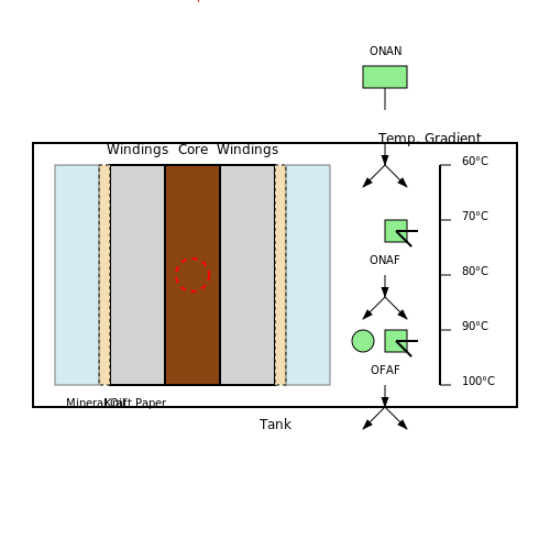
Transformer insulation must withstand high electrical stresses, thermal degradation, and mechanical forces. Solid insulation materials include cellulose-based paper (kraft or crepe paper) and aramid fibers, while liquid insulation typically involves mineral oil or ester-based fluids. For high-voltage applications, oil-impregnated paper (OIP) is dominant due to its high dielectric strength (20–50 kV/mm) and thermal conductivity (0.12–0.15 W/m·K).
The electric field distribution in insulation is governed by Laplace's equation:
where φ is the electric potential. Boundary conditions at conductor-insulation interfaces are critical for avoiding partial discharges, which accelerate aging. Modern designs use multi-layer insulation with graded permittivity to manage field stress.
Cooling Methods
Cooling systems are classified by IEEE C57.12.00 based on heat transfer mechanisms:
- ONAN (Oil Natural Air Natural): Passive cooling via natural convection.
- ONAF (Oil Natural Air Forced): Enhanced with fans for air circulation.
- OFAF (Oil Forced Air Forced): Pumps and fans actively circulate oil and air.
The heat dissipation Q follows:
where h is the heat transfer coefficient (5–25 W/m²·K for natural convection, up to 500 W/m²·K for forced oil).
Advanced Cooling Technologies
For high-power transformers (>500 MVA), directed oil flow channels and heat pipes are employed. Computational fluid dynamics (CFD) optimizes oil flow paths to minimize hotspots. Recent developments include nanoparticle-enhanced oils, which improve thermal conductivity by 10–30% by dispersing Al2O3 or TiO2 nanoparticles.
Case Study: HVDC Converter Transformers
These transformers use synthetic ester fluids (fire point >300°C) and pressboard barriers to handle DC voltage stresses. Insulation coordination must account for space charge accumulation, modeled by:
where ρ is charge density and μ is mobility.
2. Laminated Core Assembly
2.1 Laminated Core Assembly
The laminated core of a transformer is a critical component designed to minimize eddy current losses while maintaining high magnetic permeability. The core is constructed from thin sheets of electrical steel, typically silicon steel, insulated from one another by a coating of oxide or varnish. This lamination disrupts the path of eddy currents, confining them to individual layers and reducing overall energy dissipation.
Material Selection and Properties
Electrical steel, also known as silicon steel, is the predominant material due to its low hysteresis loss and high resistivity. The addition of silicon (2–4.5%) increases resistivity while reducing magnetic anisotropy. The thickness of laminations typically ranges from 0.3 mm to 0.5 mm for power transformers, with thinner laminations used in high-frequency applications.
Where:
- Pe is the eddy current loss per unit volume,
- ke is a material-dependent constant,
- f is the operating frequency,
- Bm is the peak magnetic flux density,
- t is the lamination thickness.
Core Stacking Techniques
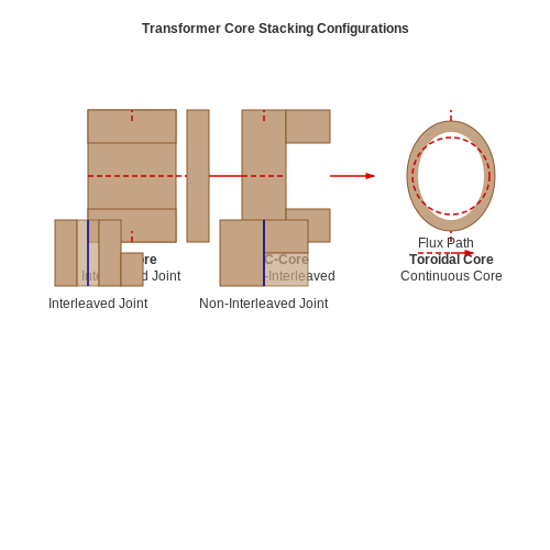
Laminations are stacked in either E-I, C-core, or toroidal configurations. The E-I arrangement is most common due to ease of manufacturing, while toroidal cores offer superior magnetic efficiency with minimal flux leakage. Each lamination layer is rotated 90° relative to the previous one to mitigate joint reluctance and flux fringing.
Interleaved vs. Non-Interleaved Stacks
In interleaved stacking, laminations alternate between left and right offsets at the joints, reducing the effective air gap. Non-interleaved stacks are simpler but suffer from higher magnetizing current due to increased reluctance at the joints.
Insulation and Coating
Laminations are coated with a thermally stable insulating layer, such as phosphate or chromate, to prevent interlayer conduction. The coating must withstand annealing temperatures (up to 800°C) without degradation. A typical insulation resistance between layers exceeds 1 MΩ to ensure negligible eddy current coupling.
Annealing Process
After stamping, laminations undergo stress-relief annealing to restore magnetic properties. The process involves heating to 750–850°C in a nitrogen-hydrogen atmosphere, followed by controlled cooling. This step reduces coercivity by up to 50%, lowering hysteresis losses.
Where:
- Wh is the hysteresis loss,
- η is the Steinmetz coefficient,
- Bm is the peak flux density.
Practical Considerations
Core assembly requires precision to avoid mechanical stress, which can degrade magnetic performance. Tightening bolts must apply uniform pressure without distorting laminations. Modern cores often use laser-cut laminations for high-precision applications, achieving tolerances within ±10 μm.
2.2 Toroidal Core Design
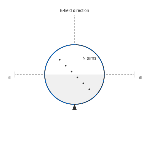
Toroidal cores offer superior magnetic performance compared to laminated or cut cores due to their closed-loop geometry, which minimizes flux leakage and reduces electromagnetic interference (EMI). The absence of air gaps in a properly wound toroid results in higher inductance per unit volume and lower core losses, making them ideal for high-efficiency power transformers and precision inductors.
Magnetic Flux Distribution
In a toroidal core with N turns carrying current I, Ampère's law yields the magnetic field strength H:
For a toroid with mean radius r, the path length is 2πr, giving:
The flux density B follows the core material's B-H curve, with saturation occurring at:
Core Material Selection
Common materials include:
- Silicon steel: Cost-effective for 50/60 Hz power applications
- Nanocrystalline alloys: High permeability (μr > 50,000) with low hysteresis losses
- Ferrites: Preferred for high-frequency operation (kHz-MHz range)
Winding Considerations
The winding window area Aw must satisfy:
where dw is the wire diameter and kf the fill factor (typically 0.7-0.9 for manual winding). For high-current applications, Litz wire reduces skin effect losses:
where δ is the skin depth and ρ the resistivity.
Thermal Management
Core losses (W/m3) follow Steinmetz's equation:
with material-specific constants k, α, and β. The thermal resistance Rθ of a toroid is approximated by:
where kt is the thermal conductivity, and ro, ri are outer and inner radii.
2.3 Shell-Type vs. Core-Type Construction
Structural Differences
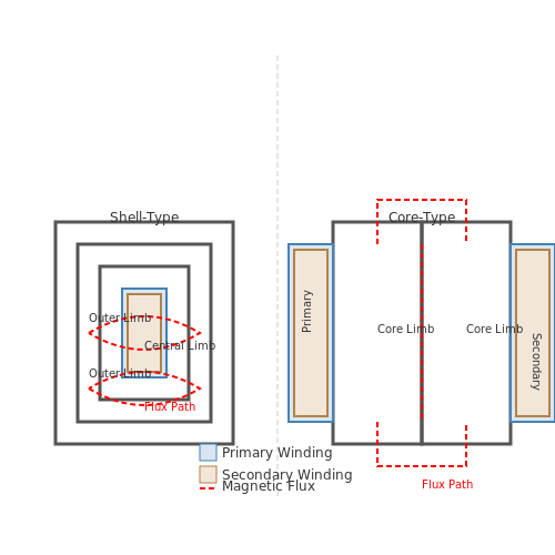
Transformers are broadly classified into shell-type and core-type based on their magnetic circuit arrangement. In core-type construction, the windings surround the laminated core, whereas in shell-type construction, the core surrounds the windings. The core-type design typically employs a rectangular or cruciform core with windings placed on opposite limbs, while the shell-type uses a central limb with windings enclosed by outer limbs.
where φ is the magnetic flux, NI is the magnetomotive force, and ℛ is the reluctance of the magnetic path. Shell-type designs exhibit lower reluctance due to shorter flux paths, reducing leakage flux.
Magnetic and Electrical Performance
Core-type transformers are favored for high-voltage applications due to better cooling and simpler winding insulation. Shell-type transformers, with their interleaved windings, offer superior mechanical strength and reduced leakage inductance, making them ideal for low-voltage, high-current scenarios. The shell-type’s distributed gap design minimizes eddy current losses, as given by:
where ke is a material constant, f is frequency, Bmax is peak flux density, and t is lamination thickness.
Practical Considerations
- Core-Type: Easier to repair, modular design, but bulkier for the same power rating.
- Shell-Type: Compact, higher mechanical stability, but complex winding repairs.
Shell-type transformers dominate in power distribution (e.g., pad-mounted transformers), while core-type is prevalent in transmission networks (e.g., EHV transformers).
Historical Context
Westinghouse’s early adoption of shell-type designs (1886) leveraged their robustness for AC power distribution, while core-type designs gained traction in Europe due to their scalability for higher voltages. Modern hybrid designs (e.g., Berry-type) blend both principles for specialized applications like traction transformers.
3. Layer Winding vs. Disc Winding
3.1 Layer Winding vs. Disc Winding
Fundamental Differences in Construction
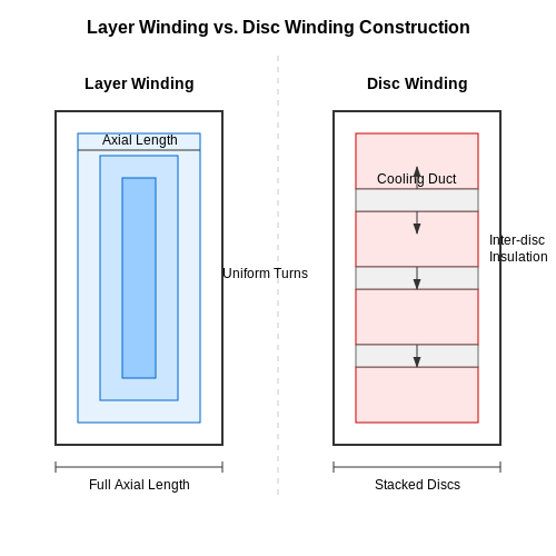
Layer winding and disc winding represent two distinct methodologies for arranging conductors in transformer coils. In layer winding, conductors are wound in multiple concentric layers, with each layer fully spanning the axial length of the coil. This results in a uniform distribution of turns per layer, minimizing radial build but increasing axial length. Conversely, disc winding consists of discrete disc-shaped sections, each containing a limited number of turns. These discs are then stacked axially, allowing for better control over radial and axial dimensions.
Electrical Characteristics
The choice between layer and disc winding significantly impacts electrical performance. Layer windings exhibit lower series capacitance due to fewer interlayer connections, making them suitable for high-voltage applications where voltage distribution must be tightly controlled. The capacitance matrix for a layer-wound coil can be approximated as:
where \( \varepsilon_r \) is the relative permittivity, \( N \) is the number of layers, \( A \) is the turn-to-turn overlap area, and \( d \) is the interlayer insulation thickness. Disc windings, however, have higher series capacitance but superior surge voltage distribution due to interleaving opportunities between discs.
Thermal and Mechanical Considerations
Thermal performance varies markedly between the two designs. Layer windings facilitate axial coolant flow, but hotspots may develop at layer transitions due to uneven cooling. Disc windings, with their segmented structure, enable radial cooling ducts, improving heat dissipation. Mechanically, disc windings offer greater robustness against short-circuit forces, as each disc acts as an independent structural unit. The mechanical stress \( \sigma \) in a disc winding under fault conditions is given by:
where \( F_{radial} \) is the radial force, \( A_{disc} \) is the cross-sectional area of a disc, \( I_{peak} \) is the peak short-circuit current, \( N_{disc} \) is the number of discs, \( r \) is the mean radius, and \( w \) is the disc width.
Practical Applications
Layer windings dominate in distribution transformers and low-power applications where simplicity and cost are prioritized. Disc windings are prevalent in power transformers (≥10 MVA) and high-voltage designs, where their superior surge withstand capability and cooling efficiency justify the added complexity. Modern hybrid designs, such as layer-disc windings, combine axial layer segments with radial disc sections to optimize both electrical and thermal performance.
Historical Context and Evolution
The disc winding technique gained prominence in the early 20th century with the advent of oil-immersed power transformers, addressing the limitations of layer windings in high-voltage scenarios. Innovations like interleaved disc windings (patented by GE in 1927) further improved voltage distribution, enabling compact EHV (Extra High Voltage) designs. Layer windings remain largely unchanged since their 19th-century origins, though modern materials like Nomex® have enhanced their thermal resilience.
3.2 High-Voltage vs. Low-Voltage Windings
Design and Material Considerations
The distinction between high-voltage (HV) and low-voltage (LV) windings in transformers arises from their operational requirements. HV windings are designed to withstand significant electric fields, necessitating thicker insulation and materials with higher dielectric strength, such as oil-impregnated paper or epoxy resin. LV windings, handling lower potentials, use thinner insulation, often polyester or enamel coatings, to minimize bulk and cost.
The conductor material also differs: HV windings frequently employ transposed conductors or Litz wire to mitigate skin and proximity effects at higher frequencies, while LV windings typically use solid or stranded copper for cost efficiency. The current density (J) in LV windings is often higher due to lower resistive losses, governed by:
where I is the current and Ac is the conductor cross-sectional area.
Winding Configuration and Electromagnetic Forces
HV windings are usually placed outermost in core-type transformers to reduce insulation complexity, while LV windings sit closer to the core. In shell-type designs, HV and LV windings may be interleaved to enhance magnetic coupling. The axial and radial electromagnetic forces (F) during short-circuit conditions scale with current squared:
where μ0 is permeability, N is turns, and g is winding gap. HV windings require robust mechanical bracing to withstand these forces.
Insulation and Thermal Management
HV windings demand graded insulation to manage non-linear voltage distribution along their length, often achieved through capacitive grading or interleaved turns. LV windings, in contrast, use uniform insulation. Thermal dissipation also differs: HV windings may employ oil ducts or forced cooling due to higher dielectric losses (Pd):
where C is capacitance, V is voltage, and tanδ is the loss tangent. LV windings prioritize convective cooling via natural oil flow or air.
Practical Trade-offs in Power Transformers
In power transformers, HV windings often use disc-type or helical arrangements for voltage distribution control, while LV windings favor layer-type designs for current handling. The turn ratio (a) directly impacts winding choices:
High-ratio transformers (e.g., 138kV/480V) require careful HV-LV separation to prevent flashover, influencing core geometry and winding spacing.
Interleaved Windings for Reduced Leakage Inductance
Leakage inductance in transformers arises due to incomplete magnetic coupling between primary and secondary windings, resulting in energy storage in non-coupled flux paths. Interleaved winding techniques minimize this effect by strategically alternating primary and secondary winding layers, thereby enhancing flux linkage and reducing the magnetic path reluctance between them.
Fundamental Principles
The leakage inductance (Lleak) of a transformer can be expressed as:
where μ0 is the permeability of free space, N is the number of turns, h is the winding height, bw is the conductor width, bins is the insulation thickness, and lm is the mean length per turn. Interleaving reduces the effective bw by distributing primary and secondary layers.
Practical Implementation
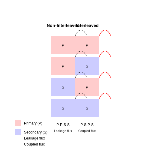
In a conventional non-interleaved design, primary and secondary windings are wound as separate blocks (e.g., P-P-P-S-S-S). Interleaving alternates these layers (e.g., P-S-P-S-P-S), which provides two key benefits:
- Reduced Effective Winding Separation: The average distance between primary and secondary conductors decreases, lowering the uncoupled flux component.
- Balanced Capacitive Coupling: Interleaving mitigates high-frequency voltage gradient issues by equalizing distributed capacitance between windings.
Quantitative Analysis
The leakage inductance reduction factor (kred) for n interleaved sections compared to a non-interleaved design is:
For example, a transformer with 4 interleaved layers exhibits a 16× reduction in leakage inductance compared to a non-interleaved equivalent.
High-Frequency Considerations
At switching frequencies above 100 kHz, interleaving becomes critical due to:
- Skin and proximity effects increasing AC resistance
- Parasitic capacitance forming resonant circuits with leakage inductance
The optimal interleaving scheme balances:
- Leakage inductance reduction
- Winding proximity losses
- Manufacturing complexity
Industrial Applications
Modern power electronics designs implement interleaving in:
- LLC resonant converters (reduces circulating currents)
- High-voltage DC-DC converters (improves voltage sharing)
- Planar transformers (compensates for low aspect ratio windings)
The technique shows particular effectiveness in flyback transformers, where leakage inductance directly impacts snubber design and switching losses. Experimental measurements on 1 kW prototypes demonstrate 40-60% reduction in peak voltage spikes during turn-off transitions when using interleaved designs.
4. Core Stacking and Alignment
4.1 Core Stacking and Alignment
The core of a transformer is a critical component that provides a low-reluctance path for magnetic flux while minimizing eddy current losses. The construction method significantly impacts the transformer's efficiency, thermal performance, and electromagnetic behavior.
Core Materials and Lamination
Transformer cores are typically constructed from grain-oriented silicon steel (GOES) laminations, which exhibit anisotropic magnetic properties. The laminations are insulated with a thin oxide or phosphate coating to reduce interlamination eddy currents. The thickness of each lamination (t) is chosen based on operating frequency (f) to keep eddy current losses within acceptable limits:
where Pe is the eddy current loss per unit volume, Bmax is the peak flux density, ρ is the resistivity, and d is the material density.
Stacking Methods
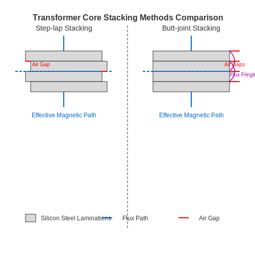
Two primary stacking techniques are employed in transformer core assembly:
- Step-Lap Stacking: Reduces air gaps at joints by overlapping laminations in a staggered pattern, minimizing flux fringing and magnetizing current.
- Butt-Joint Stacking: Simpler but introduces higher reluctance at joints, increasing no-load losses.
The stacking factor (ks), defined as the ratio of the core's effective magnetic cross-section to its physical cross-section, typically ranges between 0.90 and 0.97 for high-quality cores.
Alignment and Mechanical Stress
Precise alignment of laminations is essential to prevent:
- Local saturation due to uneven flux distribution.
- Vibrational noise caused by loose laminations.
- Increased hysteresis losses from mechanical stress.
Core clamping must apply sufficient pressure to prevent movement while avoiding excessive stress that degrades magnetic properties. The optimal clamping pressure (Pc) can be estimated as:
where E is Young's modulus for the core material, L is the core length, and ΔL is the permissible compression.
Practical Considerations in Manufacturing
In industrial production, automated stacking systems use vision-based alignment to achieve tolerances below 50 μm. Laser cutting or chemical etching may be employed for high-frequency transformers to maintain precise lamination profiles. Annealing after stacking relieves mechanical stresses introduced during cutting and assembly.
For large power transformers, core grounds are installed at strategic locations to prevent circulating currents between laminations while maintaining a safe path for fault currents.
4.2 Winding Placement and Fixation
Winding Configurations
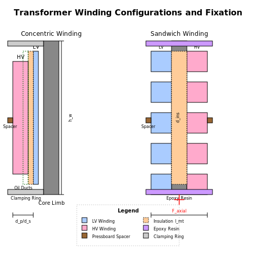
The spatial arrangement of windings directly impacts leakage inductance, parasitic capacitance, and thermal performance. Concentric winding, where primary and secondary coils are wound concentrically around the core limb, is the most common configuration for power transformers. The high-voltage winding is typically placed outside to simplify insulation requirements, while the low-voltage winding sits closer to the core.
For high-frequency applications, sandwich (interleaved) winding reduces leakage inductance by alternating primary and secondary layers. The leakage inductance Lleak for sandwich winding can be derived from:
where lmt is the mean turn length, hw the winding height, dins the insulation thickness, and dp, ds the primary/secondary conductor thicknesses.
Winding Fixation Techniques
Mechanical stability under short-circuit forces is critical. Axial forces Faxial during faults reach:
where Isc is the short-circuit current and Rmean the mean winding radius. Common fixation methods include:
- Epoxy impregnation: Fills interstitial spaces with thermally conductive resin, providing both mechanical anchoring and improved heat transfer
- Pressboard spacers: Radial spacers create oil ducts for cooling while preventing winding collapse
- Clamping rings: Stainless steel rings compress windings axially, countering Lorentz forces
Insulation Systems
Inter-turn insulation must withstand the maximum electric field Emax occurring at the inner winding radius Rin:
Modern designs use aramid papers or polyimide films for high thermal class (180°C+) insulation. Oil-immersed transformers employ kraft paper with oil impregnation, where the dielectric strength follows an inverse power-law relationship with paper density.
High-Frequency Considerations
Above 10 kHz, proximity and skin effects dominate losses. The optimal strand diameter dopt for Litz wire is:
where f is the operating frequency. Twisting pitch must be less than the skin depth to ensure current sharing among strands. Winding layers are often transposed to equalize flux linkage.
4.3 Vacuum Impregnation and Varnish Treatment
Transformer windings and cores are subjected to mechanical stress, thermal cycling, and environmental factors such as moisture and contaminants. To mitigate these effects, vacuum impregnation and varnish treatment are employed to enhance dielectric strength, thermal conductivity, and mechanical stability.
Vacuum Impregnation Process
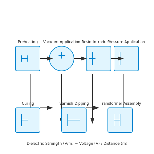
The vacuum impregnation process involves removing air and moisture from the winding structure before introducing an insulating resin. The key steps include:
- Preheating: The transformer assembly is heated to remove absorbed moisture and volatile compounds, typically at 80–120°C for several hours.
- Vacuum Application: A high vacuum (≤ 1 mbar) is applied to evacuate air from interstitial spaces within the winding.
- Resin Introduction: The impregnating resin (epoxy, polyester, or silicone-based) is introduced under vacuum, ensuring complete penetration into the winding layers.
- Pressure Application: After resin saturation, pressure (2–6 bar) may be applied to further enhance resin penetration.
- Curing: The resin is polymerized through controlled heating, forming a solid dielectric barrier.
The effectiveness of vacuum impregnation is quantified by the void-fill ratio, given by:
where \( \eta \) is the fill ratio, \( V_{\text{resin}} \) is the volume of resin absorbed, and \( V_{\text{voids}} \) is the total void volume in the winding structure. High-performance transformers achieve \( \eta > 95\% \).
Varnish Treatment
Varnish treatment is an alternative or supplementary process where a thin, insulating coating is applied to windings. Common varnishes include:
- Polyurethane: Provides excellent moisture resistance and flexibility.
- Epoxy: Offers superior mechanical rigidity and thermal stability.
- Silicone: Used in high-temperature applications due to its thermal endurance.
The varnish is applied via dipping, spraying, or trickle coating, followed by curing at elevated temperatures. The dielectric strength improvement is modeled by:
where \( E_{\text{post}} \) and \( E_{\text{pre}} \) are the post- and pre-treatment dielectric strengths, \( \Delta E \) is a material-dependent constant, \( d_{\text{varnish}} \) is the varnish thickness, and \( d_0 \) is a reference thickness (typically 0.1 mm).
Practical Considerations
In industrial applications, the choice between vacuum impregnation and varnish treatment depends on:
- Winding Complexity: Vacuum impregnation is preferred for tightly wound, multilayer designs.
- Thermal Requirements: Varnishes with high thermal conductivity (e.g., alumina-filled epoxy) improve heat dissipation.
- Manufacturing Throughput: Varnish dipping is faster but may require multiple coats for optimal performance.
Modern high-voltage transformers often combine both methods—vacuum impregnation for deep penetration and varnish coating for surface protection.
5. Turns Ratio and Polarity Tests
5.1 Turns Ratio and Polarity Tests
Fundamentals of Turns Ratio
The turns ratio a of a transformer is defined as the ratio of the number of turns in the primary winding (Np) to the number of turns in the secondary winding (Ns):
For an ideal transformer, this ratio directly determines the voltage transformation:
In practice, deviations occur due to leakage flux, core losses, and winding resistance. The turns ratio can be experimentally determined using a variable AC voltage source and precision voltmeters.
Measurement Procedure
To measure the turns ratio:
- Apply a known AC voltage Vp to the primary winding
- Measure the induced voltage Vs on the secondary winding
- Calculate the ratio a = Vp/Vs
For high-accuracy measurements, use a ratio bridge or specialized transformer turns ratio testers that account for phase angles and harmonic distortions.
Polarity Tests
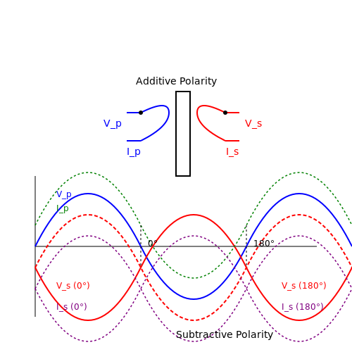
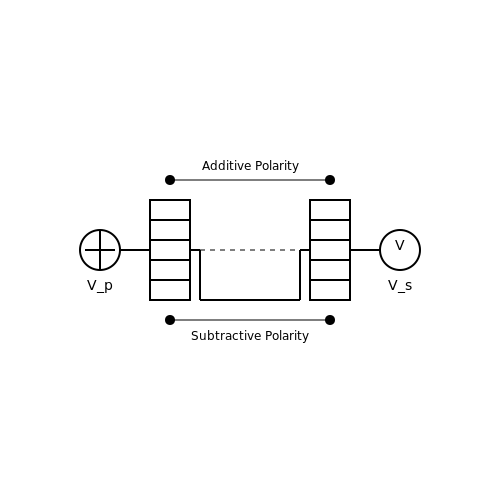
Transformer polarity indicates the relative instantaneous voltage directions between primary and secondary windings. Two types exist:
- Additive polarity: Windings are connected such that voltages add
- Subtractive polarity: Windings are connected such that voltages subtract
The standard test method involves:
- Connecting one primary lead to one secondary lead
- Applying a reduced voltage to the primary
- Measuring the voltage across the remaining leads
If the measured voltage is greater than the applied voltage, the transformer has additive polarity. If less, it has subtractive polarity.
Practical Considerations
When performing these tests:
- Use low excitation voltages (10-25% of rated voltage) to avoid saturation
- Account for phase shifts in three-phase transformers
- Consider the effects of tap changers on ratio measurements
- Verify consistency across multiple measurements
Modern automated test systems can perform both turns ratio and polarity tests simultaneously, providing comprehensive transformer characterization.
5.2 Insulation Resistance and Dielectric Strength Tests
Insulation Resistance Testing
Insulation resistance (IR) testing evaluates the integrity of insulating materials in a transformer by measuring the leakage current under an applied DC voltage. The test is governed by Ohm's Law, where the insulation resistance is calculated as:
where Rins is the insulation resistance (Ω), VDC is the applied DC voltage (V), and Ileakage is the measured leakage current (A). The test is typically performed at voltages ranging from 500 V to 10 kV, depending on the transformer's rated voltage.
Polarization Index (PI), a derived metric, assesses insulation quality by comparing resistance measurements at two time intervals (usually 1 minute and 10 minutes):
A PI value below 1.0 indicates moisture or contamination, while a value above 2.0 suggests healthy insulation.
Dielectric Strength Testing
Dielectric strength testing determines the maximum electric field an insulating material can withstand before breakdown. The test applies an AC or impulse voltage (e.g., lightning surge) to the insulation system while monitoring for breakdown. The dielectric strength Ebd is given by:
where d is the insulation thickness (m). Standard test voltages follow IEEE C57.12.90 or IEC 60076-3, often applying twice the rated voltage + 1 kV for 1 minute.
Practical Considerations
- Temperature correction: Insulation resistance decreases with temperature. The corrected value at 20°C is:
where k is a material-dependent constant (typically 1.5–2.0 for oil-paper insulation).
- Moisture effects: Relative humidity >60% can artificially lower IR measurements.
- Test sequencing: Dielectric tests should follow IR tests to avoid damaging weakened insulation.
Case Study: Oil-Filled Transformer
In oil-paper insulated transformers, dielectric strength tests often include oil sampling. The oil's breakdown voltage must exceed 30 kV (per ASTM D877) for voltages ≤69 kV. Contaminants like water (≥35 ppm) or particulates (>500 nm) reduce dielectric strength nonlinearly:
where Cw and Cp are water and particulate concentrations, respectively.
5.3 Load and Temperature Rise Tests
Purpose and Methodology
Load and temperature rise tests are critical for validating a transformer's thermal performance under operational conditions. These tests ensure that the transformer can handle rated power without exceeding permissible temperature limits, which could degrade insulation or reduce lifespan. The test involves applying a load equivalent to the transformer's rated capacity while monitoring temperature increases in the windings, core, and oil (for oil-filled transformers).
Test Setup and Instrumentation
The test requires precision instrumentation to measure:
- Winding temperature: Measured using resistance thermometers or embedded thermocouples.
- Oil temperature (if applicable): Monitored via top-oil and bottom-oil thermometers.
- Ambient temperature: Recorded to normalize temperature rise data.
- Load current: Applied using a variable load bank or back-to-back testing with another transformer.
Temperature Rise Calculation
The temperature rise of the winding is determined by the change in resistance, which varies linearly with temperature. The winding temperature rise \( \Delta T \) is calculated using:
where:
- \( R_1 \): Initial resistance at ambient temperature \( T_a \).
- \( R_2 \): Final resistance under load.
- \( T_1 \): Initial winding temperature (typically ambient).
- \( k \): Material constant (235 for copper, 225 for aluminum).
Thermal Time Constants and Steady-State Conditions
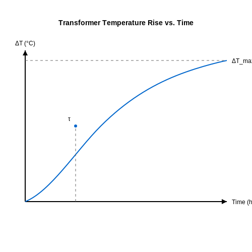
Transformers exhibit thermal inertia, characterized by their thermal time constant \( \tau \), which determines how quickly they reach steady-state temperature. The time-dependent temperature rise \( \Delta T(t) \) follows:
where \( \Delta T_{max} \) is the maximum permissible rise under continuous load. Measurements are taken at intervals until steady-state is confirmed (typically when three consecutive readings vary by less than 1°C).
Standards and Compliance
Tests must adhere to international standards such as:
- IEEE C57.12.90: For dry-type and liquid-immersed transformers.
- IEC 60076-2: Specifies permissible rises (e.g., 65°C for oil-immersed windings).
Practical Considerations
In real-world applications, overload conditions must also be evaluated. Short-term overloads (e.g., 150% load for 2 hours) should not cause irreversible damage. Modern designs use thermally upgraded insulation (e.g., Nomex) to enhance thermal endurance.
6. Standard Texts on Transformer Design
6.1 Standard Texts on Transformer Design
- PDF 6 DESIGN PARAMETERS 4 6.1 Glossary and Definitions 4 6.2 Standard ... — 6.8.5 Construction requirements 32 6.9 Equipment Fault Ratings 34 6.10 Transformer Vector Groups and technical characteristics 36 6.11 Network Electrical Design 40 6.11.1 Overhead lines impedances 40 6.11.2 Transformer regulation 40 6.11.3 Volt drop calculations 41 6.11.4 Volt drop allocation 44 6.11.5 Diversity 48
- TRANSFORMERS AND INDUCTORS FOR POWER ELECTRONICS - Wiley Online Library — ISBN 978-1-118-54467-9 - ISBN 978-1-118-54468-6 1. Electric transformers-Design and construction. 2. Electric inductors-Design and construction. I. W€olfle, Werner H. II. Title. TK2551.H87 2013 621.3104-dc23 2012039432 ISBN 978-1-119-95057-8 Set in 10/12pt Times-Roman by Thomson Digital, Noida, India
- PDF Power transformers -- Part 1: General (IEC 60076-1:2011 (EQV)) - SAIGlobal — The text of document 14/675/FDIS, future edition 2 of IEC 60076-1, prepared by IEC TC 14, Power transformers, was submitted to the IEC-CENELEC parallel vote and was approved by CENELEC as EN 60076-1 on 2011-05-25. This European Standard supersedes EN 60076-1:1997 + A1:2000 + A12:2002.
- Transformer Design and Manufacturing Manual Robert G Wolpert 2004 — 312546222 Transformer Design and Manufacturing Manual Robert G Wolpert 2004 - Free download as PDF File (.pdf), Text File (.txt) or read online for free. ... CHAPTER 6.0 CONVERTER TRANSFORMERS 6. 1 The saturating tra nsformer 6.2 Core material 6.3 Control winding voltage 6.4 Design criteria 6.4. 1 ... most electronic transformers, and in this ...
- PDF Transformer Engineering: Design, Technology, and Diagnostics — 10.3 Classification of Transformer Tanks 422 10.4 Tank Design 425 10.5 Methods of Analysis 427 10.6 Overpressure Phenomenon in Transformers 432 10.7 Seismic Analysis 433 10.8 Transformer Noise: Characteristics and Reduction 436 10.9 Transport Vibrations and Shocks 442 References 442
- Specifications for Transformers and Reactors - Design and Construction ... — Note that there is some overlap between identification of functional requirements (in Chap. 3) and specification of design and construction (in Chap. 4), e.g., concerning environmental conditions.. Depending on the limits of contractual responsibility or scope of supply, additional information may be required to ensure that all purchaser or user requirements are communicated to the supplier.
- PDF Section 4 - Power Transformer Design - Texas Instruments — Section 4 - Power Transformer Design Power Transformer Design This Section covers the design of power trans-formers used in buck-derived topologies: forward converter, bridge, half-bridge, and full-wave center-tap. Flyback transformers (actually coupled induc-tors) are covered in a later Section. For more spe-
- PDF Transformer Design Principles - api.pageplace.de — 8.7.6.1 Autotransformer with Buried Delta Tertiary and Fault on LV Terminal ..... 201 8.7.6.2 Power Transformer with Fault on Delta Tertiary ..... 202 8.7.6.3 Power Transformer with Fault on Ungrounded Y
- Electronics/Transformer Design - Wikibooks — The designer first needs several known factors to design a transformer. For a transformer using a sine or square wave, one needs to know the incoming line voltage, the operating frequency, the secondary voltage(s), the secondary current(s), the permissible temperature rise, the target efficiency, the physical size one can use, and the cost limitations.
- PDF Power and Distribution Transformers; Practical Design Guide — First edition published 2021 by CRC Press 6000 Broken Sound Parkway NW, Suite 300, Boca Raton, FL 33487-2742. and by CRC Press 2 Park Square, Milton Park, Abingdon, Oxon, OX14 4RN
6.2 IEEE and IEC Standards
- IEC 60076-2:2011 - Power transformers - iTeh Standards — Transformers covered by this document comply with the relevant requirements prescribed in the IEC 60076 standards or IEEE C57 standards. This second edition of IEC/IEEE 60076-16 cancels and replaces IEC 60076-16:2011, and constitutes a technical revision. The main changes with respect to the previous edition are as follows:
- PDF Edition 2.0 2018-09 INTERNATIONAL STANDARD — IEC/IEEE 60076-16:2018 - 5 - IEC/IEEE 2018 International Standard IEC/IEEE 60076- 16 has been prepared by IEC technical committee 14: Power transformers, in cooperation with Performance Characteristics Subcommittee of the IEEE Power and Energy Society 1, under the IEC/IEEE Dual Logo Agreement between IEC and IEEE.
- PDF Overview of IEC/TS 60076-20 Ed. 1.0: Power Transformers - Part 20 ... — This part of IEC 60076 is applicable to transformers in the scope of IEC 60076-1. ... In this standard transformers includes both separate winding transformers and autotransformers. 3. Definitions ... is the rated power of the transformer or autotransformer as defined in IEEE C57.12.80 on which P k is based. S u is used to distinguish from S r.
- IEC 60076-21:2011 - Power transformers - iTeh Standards — IEC 60076-21:2011/IEEE Std C57.15:2009 - Description of design types, tables of 50 Hz and 60 Hz ratings, supplementary ratings, construction, and available accessories are provided. Methods for performing routine and design tests applicable to liquid-immersed single and three-phase step-voltage regulators are described. Winding resistance measurements, polarity tests, insulation power factor and
- PDF Comparison of Loading Guide Standards IEEE and IEC — IEEE Std C57.15™, IEEE Standard Requirements, Terminology, and Test Code for Step-Voltage Regulators IEEE Std C57.100TM, Standard Test Procedure for Thermal Evaluation of Insulation Systems for Liquid-Immersed Distribution and Power Transformers 2 IEC 60076-1, Power transformers - Part 2: Temperature rise for liquid-immersed transformers
- PDF Edition 2.0 2018-12 INTERNATIONAL IEEE Std C57.15™ STANDARD — Tel.: +41 22 919 02 11 [email protected] [email protected] www.ieee.org www.iec.ch About the IEC The International Electrotechnical Commission (IEC) is the leading global organization that prepares and publishes International Standards for all electrical, electronic and related technologies. About the IEEE
- A Comparative Study of IEC 76 and ANSI C57.12 on Transformers — This paper will be of interest to those who are looking for a quick comparison of the standards, without going into much details. Also it is intended as a reference for the different clauses in both ANSI/IEEE and IEC. Standards IEC ANSI/IEEE REMARKS Features 1. Usual Service Conditions IEC 76-1 Clause 1.2.1 C57.12.01- Dry Type Trfs.
- PDF Edition 1.0 2017-01 TECHNICAL SPECIFICATION - atecco.ir — Power transformers - Part 20: Energy efficiency . IEC T S 60076-2 0: 2017-01 (en) ® colour ... International Standards for all electrical, electronic and related technologies. ... IEC publishes International Standards, Technical Specifications, Technical Reports, Publicly Available Specifications (PAS) and Guides (hereafter referred to as ...
- A comparison of IEC 76 and ANSI C57.12 on transformers - Academia.edu — This paper presents a brief comparison of major parameters like service conditions, categories, impedance, temperature rises, tolerance, dielectric insulation levels, test requirements etc of transformers in IEC 76 and IEEE/ANSI C57.The understanding of IEC 76 is important for the transformer market outside USA as most of the new market are looking for transformers conforming to IEC specification.
- Comprehensive Guide to Transformer Specification: Ensuring ... - EEP — This article explores the fundamental aspects of transformer specification, focusing on voltage and power rating selection, ambient temperature considerations, and cooling methods—all of which are critical to ensuring optimal transformer performance.The discussion begins with an overview of IEC 60076, highlighting its global adoption and key provisions that define transformer design principles.
6.3 Advanced Research Papers
- TRANSFORMERS AND INDUCTORS FOR POWER ELECTRONICS - Wiley Online Library — 8.3 Measurement of Losses in a Transformer 227 8.3.1 Short-Circuit Test (Winding/Copper Loss) 228 8.3.2 Open-Circuit Test (Core/Iron Loss) 229 8.3.3 Core Loss at High Frequencies 232 8.3.4 Leakage Impedance at High Frequencies 235 8.4 Capacitance in Transformer Windings 237 8.4.1 Transformer Effective Capacitance 238
- PDF Transformer Engineering: Design, Technology, and Diagnostics — 1.4 Representation of a Transformer in a Power System 21 1.5 Open-Circuit and Short-Circuit Tests 23 1.6 Voltage Regulation and Efficiency 26 1.7 Parallel Operation of Transformers 34 References 36 2 Magnetic Characteristics 37 2.1 Construction 38
- Design Optimization of Power Electronic Transformers in Traction ... — (Power Electronic Transformers) or SSTs (Solid State Trans-formers) are defined as power electronic systems that con- ... Not enough research is done for 50/60Hz systems though. Some designs for 50Hz traction systems ... ered in this paper is a 4.16MW, 25KV, 60Hz transformer for Shinkansen series-700 [Fig.1(a)]. The analysis presented in
- Design Optimization of Power Electronic Transformers in Traction ... — In this paper an analysis of different designs of traction transformers is given. The paper describes three-limb transformer design for 7.5 MVA and 10 MVA units and two-limb transformer design for 15 MVA and 16 MVA units. Paper also represents noise level measurement results and sound intensity frequency spectrum for 16 MVA unit.
- Electronic transformer performance evaluation and its impact on PMU — The voltage transformer based on the principle of voltage divider can be divided into resistance voltage divider and resistance-capacitance voltage divider. A resistive-capacitive divider voltage transformer is discussed in this paper. Since this kind of transformer is very mature, the theoretical analysis is not outlined in this paper.
- PDF Assessment of the State-of-the-Art of Solid-State Transformer ... — traditional power system, the typical transformer serves a crucial function, but it has some limitations, including bulky size, poor voltage regulation, high weight, and volume. A solid-state transformer (SST), a fantastic mix of power electronic converters and high-frequency transformer, can therefore replace this
- Structure and the space vector modulation for a medium‐voltage power ... — 1 Introduction. The power electronic transformer (PET) is composed of a power electronic converter and a medium-/high-frequency isolation transformer [].The advantages of PET such as reduced weight/volume, flexibly power flow control, reactive power regulation, improved power quality, and increased reliability make this solution widely used in place of classic transformers in modern power ...
- PDF Energy Systems in Electrical Engineering - Springer — Series accepts research monographs, introductory and advanced textbooks, professional books, reference works, and select conference proceedings. Areas of interest include, electrical and electronic aspects, applications, and needs of the following key areas:. Biomass and Wastes Energy. Carbon Management. Costs and Marketing
- Vf‐constrained ηρ‐pareto optimisation of medium frequency transformers ... — This study deals with (efficiency-power density) pareto optimisation of medium frequency transformers (MFTs) with considerations of voltage and frequency (Vf) constraints of semiconductors for mega-watt range input-series output-parallel (ISOP) connected dual-active bridges (DABs).A simple design methodology to include the Litz wire configuration in the optimisation process is proposed.