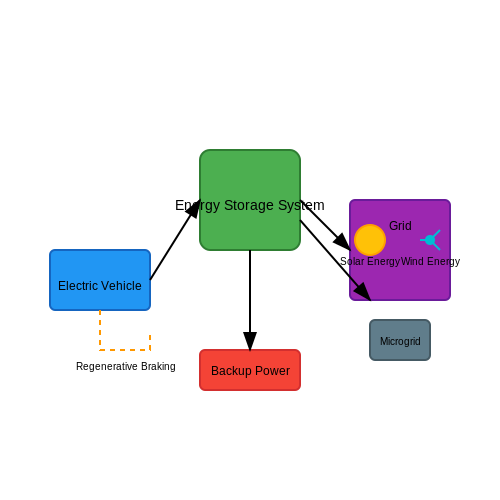
Battery Management Systems (BMS)
1. Purpose and Importance of BMS
1.1 Purpose and Importance of BMS
Battery Management Systems (BMS) serve as critical components in battery-operated devices, especially in applications ranging from electric vehicles (EVs) to renewable energy storage systems. Their primary purpose revolves around ensuring optimal performance, safety, and longevity of batteries, particularly lithium-ion types, which have rapidly become the industry standard. The BMS accomplishes this by monitoring the battery's health and operational status and managing its charge and discharge processes effectively. The significance of a BMS can be dissected into several fundamental areas, each interlinked yet distinct. One vital function is cell monitoring. A comprehensive BMS incorporates sensors to continuously measure parameters such as voltage, current, temperature, and state of charge (SoC) across individual battery cells. This data is crucial not only for maintaining optimal operating conditions but also for preventing overcharging and deep discharging, both of which can detrimentally affect battery life and performance. In parallel, a well-designed BMS contributes to thermal management. Lithium-ion batteries operate within a specific temperature range for optimal performance. The BMS can signal cooling or heating systems to maintain temperature within safe limits, leveraging thermal dynamics principles to protect the battery against risks such as thermal runaway. Another essential aspect is the balancing of cells. In a battery pack made up of multiple cells, discrepancies in charge levels can lead to suboptimal performance and premature failure. A BMS employs balancing techniques, either passive (dissipating excess energy as heat) or active (redistributing energy), to ensure uniformity in cell performance. This not only boosts the pack's overall efficacy and lifespan but also enhances reliability—a notion particularly critical for applications where power consistency is paramount, such as in grid energy storage. To comprehend the mathematical foundations underpinning these processes, consider the simple model for calculating the state of charge (SoC) of a battery, expressed as: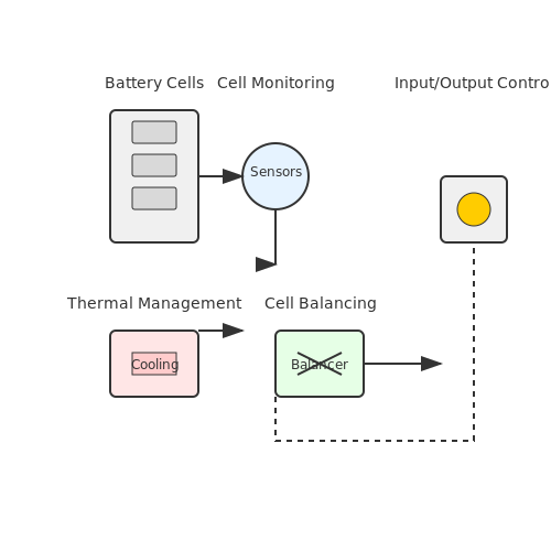
1.2 Key Components of a BMS
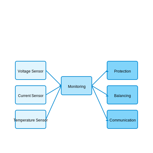
Battery Management Systems (BMS) play a crucial role in ensuring the safe, efficient, and reliable operation of battery packs, particularly in applications such as electric vehicles (EVs) and renewable energy storage systems. Understanding the key components of a BMS is essential for advanced-level practitioners looking to design or optimize these systems. The main components of a BMS can be categorized into four core functions: monitoring, protection, balancing, and communication.
Monitoring
A fundamental aspect of any BMS is its monitoring capability, which ensures that the battery operates within safe limits. This involves tracking various parameters such as voltage, current, temperature, state of charge (SoC), and state of health (SoH). Sensors play a pivotal role here:
- Voltage Sensors: These detect the voltage of individual cells or modules and help to prevent overvoltage conditions, which can lead to battery damage or thermal runaway.
- Current Sensors: Measuring the current flowing in and out of the battery is vital for calculating the SoC and determining whether the system is drawing too much power.
- Temperature Sensors: Monitoring temperature variation is critical, as elevated temperatures can degrade battery performance and lifespan.
Data collected through these sensors is processed by the BMS to evaluate the overall condition of the battery and predict how it will behave in different operating conditions. A visual representation of a BMS monitoring system could consist of a dashboard indicating real-time data from these sensors, showcasing live voltage and current readings along with temperature profiles.
Protection
Protection circuits are designed to shield the battery from operating outside its specified limits. The BMS is equipped with hardware and firmware features that can disconnect the battery from the load or charger to prevent hazardous situations. Key protective mechanisms include:
- Overcharge Protection: This feature prevents the battery from exceeding its maximum voltage, thus averting potential explosion risks.
- Overdischarge Protection: The BMS cuts off power when the voltage drops below a defined threshold, preventing permanent cell damage.
- Short Circuit Protection: This mechanism rapidly disconnects the battery to prevent overheating and catastrophic failure in the event of a short circuit.
These protective measures are crucial for maintaining the integrity and longevity of battery systems, especially in high-demand applications like electric vehicles where battery failure can lead to severe consequences.
Balancing
Battery cells within a pack can have variations in capacity and resistance, leading to unequal charge levels referred to as cell imbalance. Proper balancing ensures that each cell operates optimally throughout the charging and discharging cycles. The balancing strategies can be divided into two main types:
- Active Balancing: This method redistributes energy between cells to equalize voltages, utilizing additional circuitry and energy transfer mechanisms.
- Passive Balancing: This approach discharges stronger cells using resistors during the charging process to achieve voltage equalization.
Balancing is particularly significant in lithium-ion batteries, where imbalances can lead to reduced capacity, cycle life, and overall performance, ultimately affecting service life.
Communication
Lastly, a BMS must effectively communicate with other systems, such as the vehicle's control unit or external monitoring systems. This communication can be accomplished through various protocols, such as CAN (Controller Area Network) or UART (Universal Asynchronous Receiver-Transmitter), allowing for real-time data transfer. A well-integrated communication system enhances the functionality of the BMS by providing:
- Real-Time Monitoring: Continuous updates on battery status to ensure optimal performance.
- Intelligent Reporting: Sharing data regarding current state and health to predict maintenance needs and operational performance.
In practical applications, the integration of communication protocols enables remote monitoring of battery health, crucial for fleets of electric vehicles or large renewable energy storage systems.
In conclusion, the key components of a Battery Management System—including monitoring, protection, balancing, and communication—work together to maintain the safety and efficiency of battery systems. Recognizing these elements is fundamental for engineers and researchers aiming to innovate and improve battery technology.
1.3 Types of Battery Management Systems
Battery Management Systems (BMS) are essential components in modern battery-operated devices, responsible for ensuring the optimal performance, safety, and longevity of battery packs. Understanding the various types of BMS is critical for engineers and researchers involved in the design and implementation of energy storage solutions. In this section, we will explore the main categories of BMS, highlighting their functional characteristics, applications, and potential benefits.Centralized Battery Management Systems
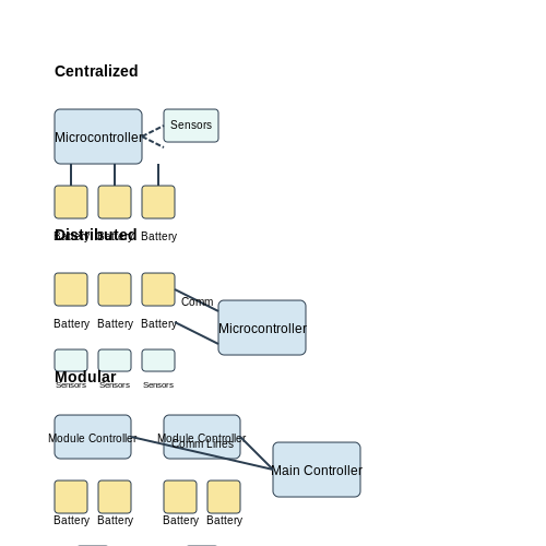
Centralized BMS are structured around a single controller that manages all battery cells and facilitates communication with external systems. In this architecture, individual cell monitoring is achieved through analog signal processing techniques, allowing the centralized unit to evaluate parameters such as voltage, temperature, and state of charge (SoC). This configuration offers simplicity in design, reduced costs due to fewer components, and ease of maintenance. However, a significant limitation arises from its scalability; as the number of cells increases, the communication lines may become congested. This can lead to delays in data processing, impacting the overall response time. Centralized BMS are commonly used in applications such as electric bicycles and smaller battery packs where cost and simplicity are prioritized over large-scale performance.Distributed Battery Management Systems
In contrast to centralized systems, distributed BMS utilizes multiple controllers placed across the battery cells. Each controller monitors a specific set of cells, collecting data and independently processing information. This approach can significantly enhance performance by localizing data collection and minimizing communication overhead. Advantages of distributed BMS include enhanced scalability, better fault tolerance, and improved battery performance. Each submodule can react quickly to localized faults without impacting the entire system. In large applications such as electric vehicles (EVs) and grid storage systems, distributed BMS systems can balance the load across the cells more effectively, leading to improved efficiency and safety.Modular Battery Management Systems
Modular BMS refer to a hybrid system combining elements of centralized and distributed architectures. Modular systems consist of modules that can be configured and optimized for specific applications. Each module can independently manage a group of cells while still communicating with a central unit for overall system coordination. This type allows for customization according to the application’s requirements, such as capacity, discharge rates, or power density. Furthermore, it provides a fail-safe mechanism, as the failure of one module does not jeopardize the entire BMS. Modular BMS are becoming increasingly popular in large-scale storage projects, renewable energy integration, and in applications requiring flexible configurations such as renewable energy vehicles.Smart Battery Management Systems
Smart BMS incorporate advanced algorithms and digital communication technologies, such as IoT (Internet of Things) connectivity, allowing real-time monitoring and control over the battery system. These systems can use machine learning techniques to predict battery behavior under various conditions, thus enhancing performance and extending battery life. By integrating various sensors and cloud capabilities, smart BMS can provide predictive maintenance, optimize charge cycles, and give users insights into battery health. They are particularly beneficial in large-scale applications where predictive data can lead to substantial cost savings and operational efficiency, such as in stationary energy storage systems or fleet management of electric vehicles. Overall, the choice of BMS relates closely to the specific application requirements, including size, performance, and budget constraints. With advancements in technology, the future promises even more robust and intelligent battery management solutions.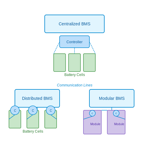
2. Battery Monitoring
2.1 Battery Monitoring
Battery Monitoring forms a crucial part of Battery Management Systems (BMS), which are pivotal in managing and maximizing the performance of rechargeable battery systems. Proper monitoring not only enhances the safety and longevity of batteries but also ensures optimal performance during operation. This section delves into the intricacies of battery monitoring, including voltage, current, temperature, and state of charge (SoC) analysis.
Understanding Battery Parameters
In order to achieve effective battery monitoring, it is essential to understand the primary parameters that influence battery performance:
- Voltage: A critical indicator of battery health, voltage levels can inform us about the operational state and capacity of the battery. Each cell in a battery pack has a nominal voltage and any significant deviation from this can signal potential issues.
- Current: The flow of current (both charge and discharge) is vital for analyzing usage patterns. The current measurement helps in understanding the battery load and can indicate operational efficiency.
- Temperature: Temperature significantly impacts battery performance and life. Excessive heat can accelerate degradation, while extremely low temperatures might reduce capacity.
- State of Charge (SoC): SoC indicates the remaining capacity in the battery, typically expressed as a percentage. Accurate SoC calculation is instrumental in preventing overcharging and discharging.
Voltage Monitoring Techniques
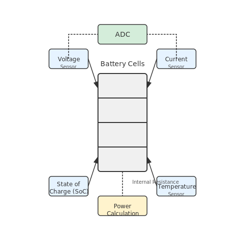
Voltage monitoring generally involves the use of sensors and analog-to-digital converters (ADCs) to continuously assess the voltage levels of individual cells in a battery pack.
The basic equation governing the voltage of a battery cell can be expressed as:
Where Vcell is the cell voltage, Vopen-circuit is the theoretical voltage without load, I is the current, and Rinternal is the internal resistance of the cell. This equation underscores that voltage measurement under load conditions is essential for providing a clear picture of a battery's performance.
Current and Power Monitoring
Current is monitored using shunt resistors and Hall effect sensors, which allow for high-precision measurements. The power consumed or produced by a battery can be expressed as:
Where P is the power in watts, V is the voltage, and I is the current. Effective power monitoring helps interpret the energy flow and overall efficiency of the battery during different operational conditions.
Temperature Monitoring
Temperature sensors such as thermocouples or thermistors can be strategically placed in a battery pack to provide real-time temperature data. Monitoring temperature profiles is important for both performance evaluation and safety:
- Excessive temperatures can lead to thermal runaway, particularly in lithium-ion battery systems.
- Temperature variations across different cells can result in capacity imbalances, increasing operational risks.
State of Charge Calculation
The State of Charge (SoC) can be computed using various methods such as:
- Voltage-Based Methods: By interpreting the open-circuit voltage across a cell, an approximate SoC can be inferred. This method is reliable but typically requires some time at rest before measurement.
- Coulomb Counting: This involves integrating the current over time, accounting for both charging and discharging cycles. The equation governing this method can be expressed as:
Where SoC(t) is the state of charge at time t, Cbat is the capacity of the battery, and I(t) is the instantaneous current
Conclusion
The ability to continuously monitor these critical parameters is essential in ensuring the reliability and efficiency of battery-operated systems. Advanced Battery Management Systems leverage sophisticated algorithms and sensor technologies to provide comprehensive monitoring, which in turn supports informed operational decisions in applications ranging from electric vehicles to renewable energy storage.
2.2 State of Charge (SOC) Estimation
State of Charge (SOC) is a critical parameter in Battery Management Systems (BMS), reflecting the current energy state of the battery as a percentage of its total capacity. Understanding SOC is crucial for efficient battery usage, longevity, and safety across various applications, including electric vehicles, renewable energy storage, and consumer electronics. Accurate SOC estimation enables effective decision-making in energy management, ultimately directly affecting operational performance and reliability.
The methods for estimating SOC can be broadly classified into two categories: model-based approaches and measurement-based approaches. The model-based techniques integrate mathematical models of battery dynamics, while measurement-based methods rely on direct battery performance metrics to infer SOC.
Mathematical Foundations of SOC Estimation
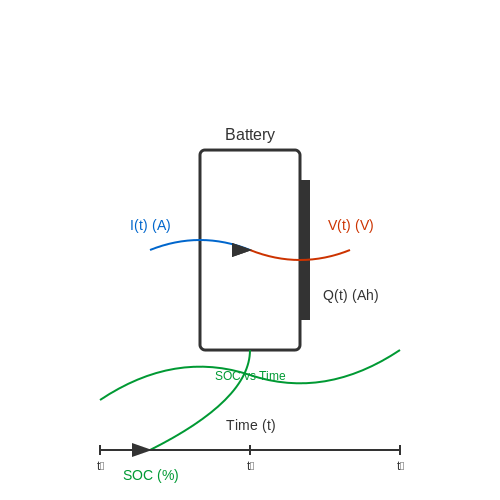
The determination of SOC fundamentally relies on knowing the battery's charge and discharge behavior. One common approach to mathematically define SOC is via the following relation:
where:
- Q is the current charge of the battery (in Ah);
- Qmax is the maximum capacity of the battery (in Ah).
While this equation provides a straightforward calculation of SOC, accurately determining Q throughout the battery's operation can be complex due to factors such as voltage fluctuations, temperature effects, and historical discharge currents. Therefore, more sophisticated approaches to SOC estimation often involve additional complexities.
Measurement-Based Approaches
Measurement-based SOC estimation techniques leverage real-time battery parameters like voltage, current, and sometimes temperature to calculate SOC. One widely used method is the Kahrady's Method, which incorporates both voltage and current measurements over time:
Here, Q(t) is the charge at time t, and I(t) is the current flowing into or out of the battery at time t. The time increment Δt should be appropriately selected based on the battery dynamics.
Another prevalent technique is the Open-Circuit Voltage (OCV) method, where SOC is estimated by measuring the steady-state voltage of the battery when not under load. The OCV correlates with SOC and provides valuable insights, although this method requires the battery to be inactive for accurate readings, limiting its real-time applicability.
Model-Based Approaches
On the other hand, model-based SOC estimation typically employs algorithms that reflect the electrochemical behavior of batteries. One popular model is the Kalman Filter, which provides a recursive solution to estimate the state of an unknown system:
Here:
- ⊕xk|k: state estimate at time k;
- Kk: Kalman Gain, which weighs the estimates and measurements;
- ⊕yk: the actual measurement parameter;
- Hk: measurement matrix indicating how the measurements correlate to the system state.
The Kalman Filter is advantageous for integrating multiple sources of data while filtering out noise, providing increasingly accurate SOC predictions as more data is incorporated.
Practical Applications and Future Trends
In real-world applications, SOC estimation plays a pioneering role in optimizing battery usage. In electric vehicles, accurate SOC estimates directly contribute to distance prediction and energy management systems, enhancing performance and user experience. Moreover, in renewable energy storage systems, improved SOC estimations help in load management and support grid stability.
Looking to the future, trends toward enhanced accuracy in SOC estimation are being driven by advancements in battery technology, data analytics, and machine learning. These innovations promise to refine estimation methodologies by providing refined battery models reflective of usage conditions, cycling patterns, and environmental factors, ensuring longevity and reliability in battery performance.
Through these advances, the challenges of accurately determining SOC can increasingly be addressed, paving the way for smarter and more efficient energy systems.
2.3 State of Health (SOH) Monitoring
Understanding State of Health (SOH) in Battery Management
The concept of State of Health (SOH) in battery management systems (BMS) plays a pivotal role in assessing the overall performance and longevity of batteries, particularly in applications involving lithium-ion cells. SOH provides insight into the battery’s capacity, efficiency, internal resistance, and overall degradation, which are crucial for optimizing battery performance and extending lifespan. Monitoring SOH allows engineers to predict potential failures and optimize maintenance schedules, thus ensuring reliability in various applications ranging from electric vehicles to renewable energy storage systems.Key Parameters for SOH Assessment
The evaluation of SOH is generally based on several key parameters, including:- Capacity: The maximum amount of charge the battery can hold compared to its rated capacity. This is often expressed in percent.
- Internal Resistance: An increase in internal resistance can signify degradation, as it reduces efficiency and increases heat during operation.
- Cycle Life: The number of charge/discharge cycles a battery can undergo before its capacity falls below a specified level.
- Voltage Deviation: Monitoring voltage levels during charging and discharging helps identify issues such as cell imbalances.
Mathematical Modeling of SOH
The mathematical representation of SOH can be described as: $$ \text{SOH} = \frac{\text{Current Capacity}}{\text{Nominal Capacity}} \times 100\% $$ This formula provides a straightforward method to quantify the health of a battery. For example, if a battery's nominal capacity is 100 Ah and its current capacity is measured at 85 Ah, the SOH would be:Techniques for SOH Monitoring
Various techniques are employed to ascertain SOH accurately:- Electrochemical Impedance Spectroscopy (EIS): This advanced technique assesses the internal resistance by applying a small alternating current and measuring the resulting voltage response across a range of frequencies.
- Coulomb Counting: This technique integrates the current over time to estimate the capacity. While effective, it may suffer from cumulative errors without proper calibration.
- Machine Learning Algorithms: Emerging approaches utilize data from multiple parameters to predict SOH more effectively. These algorithms can adapt and learn from real-time data, improving predictive accuracy over time.
Real-World Applications of SOH Monitoring
In practice, SOH monitoring is crucial across several sectors:- Electric Vehicles (EVs): Accurate SOH monitoring allows manufacturers and fleet operators to optimize battery usage, extend life, and address potential issues proactively.
- Renewable Energy Storage: For applications like solar energy storage, understanding SOH helps manage energy flow efficiently and maximize storage performance.
- Consumer Electronics: In smartphones and laptops, SOH monitoring enables users to receive timely warnings and manage battery health effectively.
2.4 Temperature Management
Temperature management is a critical aspect of Battery Management Systems (BMS), particularly for lithium-ion batteries, which are widely employed in modern applications ranging from consumer electronics to electric vehicles. The performance, efficiency, safety, and longevity of battery systems are significantly influenced by their operating temperature. This subsection aims to provide an understanding of the mechanisms behind temperature management in BMS and its importance for system reliability.
The thermal behavior of a battery during operation is governed by several factors, including charge/discharge cycles, ambient temperature, and internal resistance. As batteries cycle, they undergo chemical reactions which generate heat. Excessive heat can lead to accelerated aging, increased electrolyte degradation, and safety risks such as thermal runaway, making effective temperature management essential.
Thermal Effects on Battery Performance
At elevated temperatures, the performance of lithium-ion batteries can initially improve, leading to increased capacity and faster charging. However, this comes at the risk of accelerated aging and potential failure. Conversely, low temperatures can hinder electrochemical reactions, reducing capacity and efficiency. A balance is necessary to optimize battery performance, ensuring it operates within the recommended temperature range—typically between 20°C to 25°C.
The correlation between temperature, capacity, and internal resistance can be expressed mathematically. The Arrhenius equation provides insight into the temperature dependence of reaction rates in batteries:
Here, k is the rate constant, A is the pre-exponential factor, E_a is the activation energy, R is the universal gas constant, and T is the absolute temperature in Kelvin. As temperature increases, the rate of electrochemical reactions and the resultant capacity can increase significantly until thermal management becomes critical.
Temperature Management Strategies
To mitigate the adverse effects of temperature on battery performance, several thermal management strategies are employed in BMS:
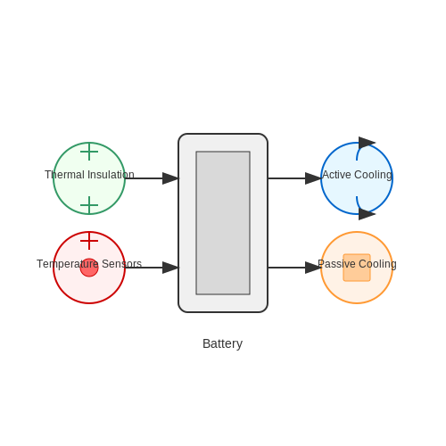
- Active Cooling/Heating: Utilizing liquid or air-based cooling systems to maintain optimal temperature ranges. Liquid cooling is often favored for its higher thermal conductivity.
- Passive Cooling: Employing materials with high thermal mass or heat sinks to dissipate heat without the need for active systems.
- Thermal Insulation: Using insulating materials to minimize heat loss or gain, particularly in extreme environmental conditions.
- Temperature Sensors: Deploying thermocouples or PT100 sensors to continuously monitor battery temperatures, providing data for real-time BMS adjustments.
In practical applications, such as in electric vehicles, effective temperature management not only extends battery life but also enhances performance during both high and low environmental conditions. For instance, Tesla’s comprehensive cooling system includes circulating coolant through the battery pack, which proactively manages heat dissipation during operation.
Case Studies and Research
Research efforts in this domain continue to evolve, with advancements in materials science leading to the development of phase change materials (PCMs) that can absorb and release heat at specific temperatures, effectively stabilizing battery temperatures under varying loads. Studies show that integrating PCMs within battery packs can enhance thermal stability, significantly improving charge cycles and overall efficiency.
Ultimately, effective temperature management is an integral component of a robust Battery Management System. It is essential not only for maximizing performance and lifespan but also for ensuring safety, making it a focal point of ongoing research and innovation in battery technology.
3. Overview of Communication Protocols
3.1 Overview of Communication Protocols
In Battery Management Systems (BMS), communication protocols serve as the backbone for effective data exchange between different components of the system. These protocols ensure that vital information about battery performance, health, and status is relayed accurately and timely. The selection of communication protocols in a BMS is influenced by various factors including data rate requirements, communication distance, power consumption, and the operational environment. Here, we will explore several prevalent communication protocols used in BMS, their underlying principles, and their practical implications.
Understanding Communication Protocols
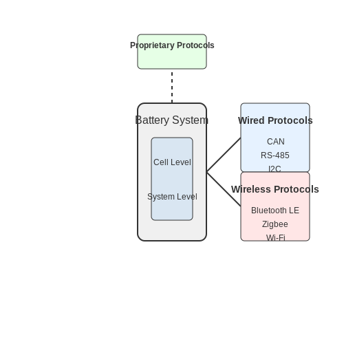
Communication protocols define rules and conventions for data transfer between devices. In a BMS, these protocols enable the exchange of critical information such as voltage levels, current rates, temperature readings, and state of charge (SoC). The communication can occur at various hierarchical levels, from the cell level to the system level, facilitating comprehensive monitoring and management of battery packs.
Three main categories of communication protocols are frequently employed in BMS:
- Wired Protocols: These include CAN (Controller Area Network), RS-485, and I2C. Such protocols are known for reliability and speed, making them suitable for applications requiring real-time data exchange.
- Wireless Protocols: Examples include Bluetooth Low Energy, Zigbee, and Wi-Fi. These protocols allow for greater flexibility in device placements and are ideal for applications where wiring is impractical or costly.
- Proprietary Protocols: Many manufacturers develop custom protocols tailored to their specific hardware configurations, offering optimized performance but often at the cost of interoperability.
Wired Communication Protocols
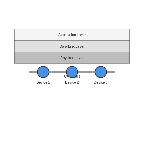
Among the wired protocols, the CAN bus is particularly significant in automotive applications, providing a robust form of communication that supports real-time operation. With its error-checking capabilities and resilience to electrical noise, CAN establishes a fault-tolerant communication network, which is paramount in motor vehicles where failures can lead to hazardous situations. The architecture allows for the connection of multiple devices on a single bus, enhancing scalability in battery systems.
Here, \( R_{CAN} \) represents the resistance to data transmission, \( L \) is the length of the network, and \( D \) is the data rate, which can impact the efficiency of information transfer. It is essential for BMS engineers to adequately account for these factors when designing the communication layout.
Wireless Communication Protocols
On the other hand, wireless protocols offer the unique advantage of minimizing cabling efforts. Bluetooth Low Energy (BLE) is favored for short-range applications, especially in consumer electronics for battery monitoring. BLE supports numerous devices and minimizes power consumption, which is critical for extending the lifespan of battery-operated devices.
Zigbee offers another option, particularly suitable for smart grid applications due to its low power consumption and mesh networking capability. This facilitates efficient communication across multiple sensors, significantly enhancing data gathering in BMS applications.
Proprietary Protocols: Custom Solutions
While standardized protocols like CAN and BLE serve broad applications, proprietary protocols can be designed for specific performance enhancements in unique battery systems. They allow manufacturers to fine-tune aspects such as data handling efficiency and security features. However, engineers must remain cognizant of the limitations concerning interoperability with third-party systems, a critical consideration in multi-manufacturer environments.
As the demand for efficient, reliable, and secure battery management systems continues to rise with the proliferation of electric vehicles and renewable energy systems, understanding and implementing the right communication protocol becomes paramount for engineers, researchers, and manufacturers in the field.
3.2 CAN Bus in BMS
Battery Management Systems (BMS) are pivotal for ensuring the reliability, longevity, and safety of battery packs in various applications, from electric vehicles to energy storage systems. One crucial element of a BMS is the communication interface that allows for effective monitoring and control. The Controller Area Network (CAN) bus serves as a robust and efficient communication protocol integral to modern BMS architectures.
Understanding the CAN Bus Protocol
The CAN bus, developed in the 1980s by Bosch, was originally designed for automotive applications but has since found widespread use in industrial and embedded systems due to its fault-tolerant features and real-time capabilities. At its core, the CAN bus enables multiple microcontrollers and devices to communicate with one another without a host computer, utilizing a multi-master approach.
This capability is particularly advantageous in BMS applications, where numerous cells and monitoring units must share data regarding voltage, temperature, current, and state of charge (SoC). The data bus operates with high reliability, ensuring minimal latency and high priority for critical messages, making it ideal for safety-related communications.
Architecture of CAN Bus in BMS
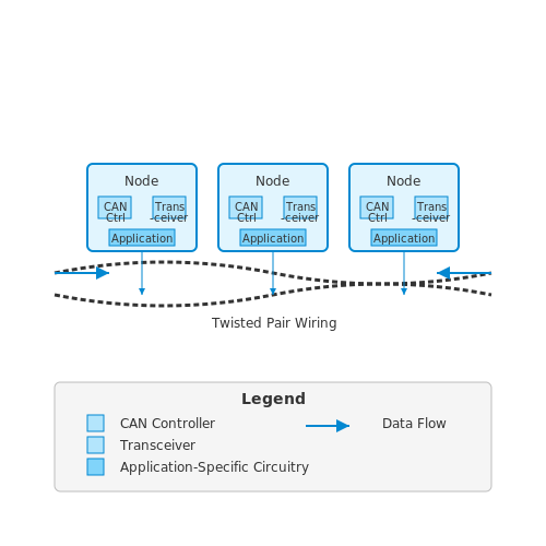
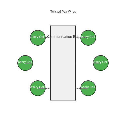
A typical BMS deployed with a CAN bus architecture includes multiple nodes, with each node representing a battery cell or a cluster of cells equipped with sensors and controllers. The nodes communicate via a twisted pair of wires, significantly reducing electromagnetic interference and enhancing data integrity. Each node periodically broadcasts its data onto the bus, which can be received and processed by any other node on the network.
Advantages of Using CAN Bus in BMS
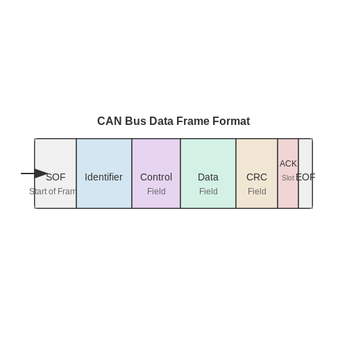
- Robustness and Fault Tolerance: The CAN protocol effectively manages communication errors through mechanisms such as cyclic redundancy checks (CRC) and acknowledgment signals. This robustness is vital in BMS, where data accuracy is critical for safe operation.
- Speed and Efficiency: CAN bus supports data rates of up to 1 Mbps, allowing for rapid updates of critical system parameters. This speed is essential for real-time monitoring and control of battery systems.
- Scalability: The CAN architecture allows for the easy addition of new nodes, accommodating future expansion of battery systems without significant redesigns.
- Reduced Wiring Complexity: The twisted-pair wiring can simplify the design compared to point-to-point wiring configurations in traditional monitoring setups.
Real-World Applications of CAN Bus in BMS
One prominent example of CAN bus applications in BMS is within electric vehicles (EVs). For instance, Tesla employs a sophisticated BMS that uses a CAN bus to manage thousands of individual battery cells across its energy storage systems effectively. This system continually monitors the health and performance, ensuring optimal operation and extending the battery life.
Another application can be found in large-scale renewable energy storage systems, where lithium-ion batteries are deployed. In these systems, CAN bus technology facilitates communications among multiple battery modules, ensuring synchronized charge and discharge cycles to enhance grid stability and efficiency.
Conclusion
In summary, the integration of CAN bus within BMS represents a pivotal advancement in battery technology management. As battery systems become increasingly complex and integral to energy solutions, the scalability, efficiency, and fault tolerance of CAN bus communications will continue to be a key enabler in the future of battery technologies.
3.3 UART and I2C Protocols
In the realm of Battery Management Systems (BMS), effective communication protocols play a crucial role, especially when implementing features such as data monitoring and control. Two popular protocols for such tasks are Universal Asynchronous Receiver-Transmitter (UART) and Inter-Integrated Circuit (I2C). Both serve different purposes and have distinct advantages depending on the BMS application requirements.Introduction to Communication Protocols
Communication protocols define the rules and conventions for data exchange between electronic devices. In the context of Battery Management Systems, efficient data communication is paramount, as real-time monitoring and control can significantly improve battery performance, safety, and longevity. Choosing the right protocol can affect system complexity, speed, and the number of devices that can be interconnected.UART Protocol: Overview and Characteristics
UART is a hardware communication protocol that facilitates asynchronous serial communication. It is widely used due to its simplicity and minimal hardware requirements. A UART interface typically consists of two lines: the transmit (TX) and receive (RX) lines. Key Characteristics of UART Include:- Asynchronous Communication: No clock signal is transmitted; instead, data is sent in the form of bits with start and stop bits to denote the beginning and end of transmission.
- Simple Hardware Requirements: Requires only two wires (TX and RX) and ground, making it easy to implement in various applications.
- No Formal Addressing: Communication occurs point-to-point between devices; thus, it is less suited for multi-device configurations absent additional protocol layers.
I2C Protocol: Overview and Applications
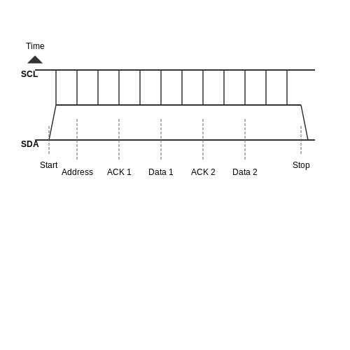
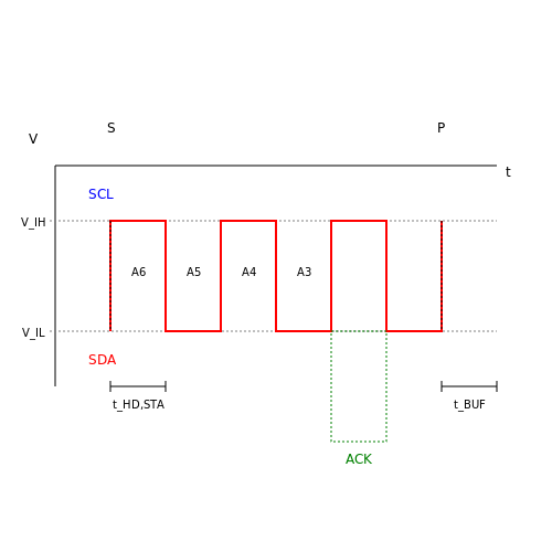
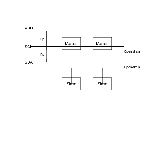
In contrast, I2C is a multi-master, multi-slave, synchronous communication protocol, which opens more advanced communication possibilities within a BMS. I2C utilizes two lines, a Serial Data Line (SDA) and a Serial Clock Line (SCL), for its operations, allowing multiple devices to share the same data bus. Key Features of I2C Include:- Multi-Master Configuration: Multiple master devices can control the bus. This feature is particularly useful in a BMS where various sensors and chips might need to communicate with a central MCU.
- Addressing: Each connected device can be assigned a unique address, which simplifies device management and integration.
- Data Locking: I2C’s centralized clocking mechanism lets devices synchronize effectively, maintaining data integrity across multiple communications.
Comparative Analysis: UART vs. I2C
When comparing UART and I2C, several critical considerations emerge: 1. Speed and Efficiency: UART typically operates at higher baud rates up to a maximum speed defined by the hardware (e.g., 115200 bps), whereas I2C usually supports speeds of 100 kbps (Standard Mode) and up to 1 Mbps (Fast Mode). However, I2C's overhead may affect total throughput. 2. Complexity and Scalability: I2C is significantly more complex not only due to its multi-device capability but also its error-checking mechanisms. UART, while simpler and suitable for point-to-point communication, does not scale for larger systems without additional configuration. 3. Application Flexibility: While UART shines in cases where a straightforward, high-speed transmission is necessary, I2C excels in environments requiring the management of multiple devices with shared resources. Deciding between UART and I2C in a BMS primarily depends on the specific application's needs relating to scalability, speed, and complexity. For instance, a BMS architecture designed for compact electronic systems may benefit from the simplicity and speed of UART, whereas I2C would be ideal for more extensive systems including multiple battery cells and various sensors.Conclusion
In closing, both UART and I2C communication protocols hold value in the design of Battery Management Systems, each with unique strengths suited for different application contexts. As you design or refine your BMS, evaluating the requirements concerning device complexity, communication speed, and overall system architecture will lead you to an informed choice between these protocols. Understanding their nuances will undoubtedly facilitate more efficient and responsive battery management solutions in forthcoming applications.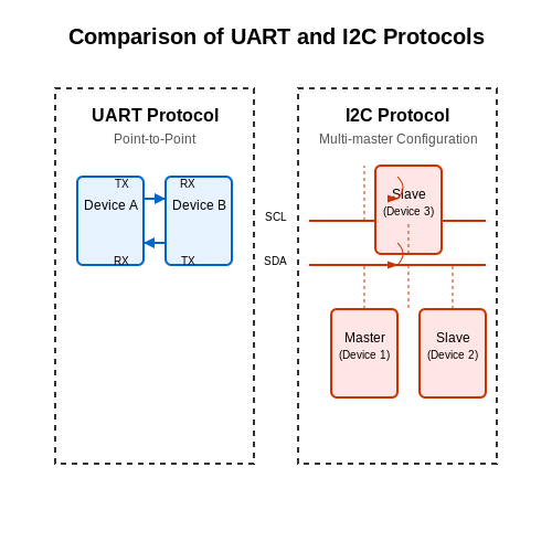
4. Overvoltage and Undervoltage Protection
4.1 Overvoltage and Undervoltage Protection
Battery Management Systems (BMS) play a vital role in modern energy storage systems, particularly in electric vehicles (EVs) and renewable energy applications. One of the core functionalities of a BMS is overvoltage and undervoltage protection, ensuring the health and longevity of battery cells.
Understanding these protection mechanisms requires a grasp of how batteries behave under varying load conditions. When a battery is charged or discharged, its voltage fluctuates. If this voltage exceeds safe limits during charging (overvoltage), or falls below a critical threshold during discharging (undervoltage), it can lead to critical failure modes such as thermal runaway, capacity loss, or irreversible damage.
Overvoltage Protection
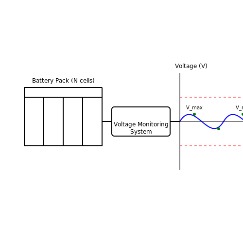
Overvoltage occurs when the voltage across a cell or battery pack exceeds the manufacturer's specified maximum voltage. For lithium-ion batteries, for example, this limit typically ranges from 4.2V to 4.3V per cell. Exceeding this limit can initiate electrolytic decomposition, where the electrolyte breaks down, leading to gas generation, heating, and potential thermal runaway.
To prevent overvoltage scenarios, BMS designs often implement a series of voltage sensing circuits and protection relays. The BMS continuously monitors the voltage of each cell and can disconnect the charger if the voltage exceeds a preset threshold. Furthermore, active balancing techniques may also be employed to equalize cell voltages during charging, preventing any cell from reaching an overvoltage state.
Mathematical Analysis of Overvoltage Conditions
Consider a battery with N cells in series, where each cell has a maximum voltage rating V_{max}. The total allowable voltage for the battery pack can be described by:
To maintain optimal performance, ensuring that the applied charging voltage \( V_{charged} \) does not exceed V_{total_max} is critical:
Undervoltage Protection
Undervoltage is equally significant and occurs when the cell voltage drops below a defined limit, typically around 2.5V to 3.0V for lithium-ion cells. Prolonged operation at undervoltage can lead to lithium plating, capacity degradation, and poor recovery during subsequent recharge cycles.
BMS designs incorporate undervoltage protection by monitoring cell voltages and disconnecting the load or triggering alerts when voltages fall below preset levels. This can be represented by a similar formula:
Where V_{min} is the per-cell minimum safe operating voltage. The condition for maintaining stable battery discharge can be formulated as follows:
Practical Relevance and Applications
In real-world applications, effective overvoltage and undervoltage protection is crucial for maximizing battery life and ensuring safety. For instance, in electric vehicles, BMS ensure that battery performance is optimized while providing real-time feedback to the driver regarding battery health.
Moreover, as the global emphasis on renewable energy grows, effective BMS technologies facilitate the integration of battery storage systems, thus stabilizing output from intermittent generation sources such as solar and wind energy.
In summary, the balance between overvoltage and undervoltage protection is essential for safeguarding energy storage systems, maximizing efficiency, and ensuring usability across various applications.
4.2 Overcurrent Protection
Overcurrent protection is a critical aspect of Battery Management Systems (BMS) that ensures the safety and reliability of battery-operated devices. This protection mechanism is necessary to prevent excessive currents from damaging the battery cells, potentially leading to catastrophic failures such as thermal runaway or cell rupture. Understanding overcurrent conditions, their effects, and the strategies to mitigate them is paramount for engineers and researchers working in energy storage systems.Understanding Overcurrent Conditions
Overcurrent refers to situations where the current flowing through the battery exceeds its rated capacity. This can occur due to various reasons, including:- Short circuits within the system
- Improper load management
- Battery faults or degradation
Consequences of Overcurrent
The consequences of not implementing effective overcurrent protection can be severe:- Thermal Runaway: Excessive heat can initiate thermal runaway, where the temperature increase induces further reactions within the battery, leading to potential explosions or fire hazards.
- Cell Damage: Prolonged overcurrent can physically damage internal battery components, leading to capacity loss and reduced lifespan.
- Cost Implications: Neglecting overcurrent protection can lead to costly replacements or safety recalls for battery-powered devices.
Types of Overcurrent Protection
Several methods can be employed for protecting against overcurrent conditions in Battery Management Systems:Fuses
Fuses are one of the oldest forms of overcurrent protection. They are designed to physically disconnect the circuit when the current exceeds a certain rating. The primary disadvantage of fuses is that they are single-use devices; once they blow, they must be replaced.Resettable Fuses (Polyfuses)
Resettable fuses, or polyfuses, provide a more convenient solution. They temporarily interrupt the circuit when the current exceeds the rated value but can reset themselves once the fault is cleared. This flexibility is particularly beneficial in user-centric applications where minimal intervention is desired.Electronic Circuit Breakers
Modern approaches incorporate electronic circuit breakers that use solid-state components to monitor current flow continuously. They can react faster than traditional fuses and can be reprogrammed or adjusted according to changing requirements. The ability to set multiple trip levels and integrate with the BMS for real-time diagnostics is an added advantage.Current Sensing and Control
A more sophisticated approach involves the use of current sensing devices combined with control algorithms. By continuously monitoring the current using sensors, the BMS can adjust the load dynamically or disconnect the battery from the charge/load in the case of overcurrent. Techniques such as using shunt resistors or Hall effect sensors enable accurate current measurement.Implementation Considerations
When implementing overcurrent protection, several factors must be considered:- Selection of Threshold: The threshold for overcurrent must be calculated based on the battery specifications and application requirements to avoid nuisance tripping while protecting against actual risks.
- Response Time: Systems must be designed for quick response times to minimize any potential damage or hazards.
- Integration with BMS: Ensure that the implemented protection methods are well integrated with the BMS for coherent operation and real-time monitoring.
Conclusion
The significance of overcurrent protection in Battery Management Systems cannot be overstated. As battery technologies evolve and applications become more demanding, the need for advanced protection strategies will only grow. Equipped with an understanding of overcurrent dynamics, combined with the right mitigation strategies, engineers and researchers will enhance the safety and reliability of battery-operated systems, paving the way towards future innovations in energy storage.4.3 Thermal Management and Safety
In the development and implementation of Battery Management Systems (BMS), the aspects of thermal management and safety are critical for ensuring optimal performance, longevity, and safety of battery packs. Given the rapid expansion of applications reliant on batteries—ranging from consumer electronics to electric vehicles—the management of thermal risks and the adherence to safety protocols cannot be overstated.
Understanding Thermal Dynamics in Battery Systems
Heat generation in batteries primarily results from internal resistance within the cells during charge and discharge cycles. This phenomenon is governed by Joule’s law, which can be expressed as:
Here, Q is the heat generated, I is the current, R is the internal resistance, and t is the time for which the current flows. Overcharging, high discharge rates, or poor thermal design can cause excessive heat, leading to reduced efficiency and, potentially, thermal runaway—a scenario in which increased temperatures lead to further reactions that create even more heat.
Thermal Management Techniques
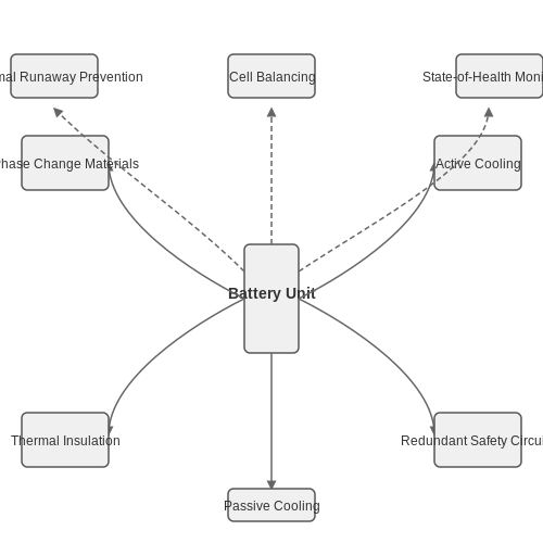
Effective thermal management involves various strategies aimed at maintaining battery temperatures within safe limits. These include:
- Active Cooling: Utilizing liquid or air cooling systems to dissipate heat effectively. These systems can be designed to dynamically adjust based on the battery temperature.
- Passive Cooling: Designing battery enclosures with materials that enhance heat dissipation, such as aluminum or other thermally conductive materials.
- Phase Change Materials (PCMs): Incorporating materials that absorb excess heat during phase transitions can help maintain stable temperatures.
- Thermal Insulation: Insulating layers can prevent external thermal fluctuations from influencing the battery temperature.
These methods showcase not only engineering principles but also an understanding of heat transfer mechanisms, which are essential in the development of effective thermal management solutions.
Safety Protocols in Battery Management Systems
The safety of battery systems is paramount, especially in applications involving higher energy densities, such as electric vehicles or energy storage systems. Key safety measures include:
- Redundant Safety Circuits: Implementing multiple layers of safety, such as fuses and thermal cut-offs, ensures that a single failure does not lead to catastrophic outcomes.
- State-of-Health Monitoring: Continuous assessment of battery health through sensors that monitor temperature, voltage, and current to prevent unsafe operating conditions.
- Cell Balancing: Ensuring equal charge distribution among cells can prevent overcharging and overheating. Both passive and active balancing can be employed, with active systems typically providing more precision.
- Thermal Runaway Prevention: Advanced algorithms can detect abnormal conditions leading to thermal runaway and initiate protective measures, such as disconnecting the battery from the load.
Implementing these safety protocols not only protects the battery systems but also enhances user confidence and reliability across applications.
Real-World Applications and Case Studies
In practical applications, automotive manufacturers have invested heavily in designing sophisticated thermal management systems for electric vehicles. For instance, Tesla employs a cooling system that circulates coolant through the battery pack, thus maintaining optimal thermal conditions and prolonging battery life. Moreover, safety measures integrated in their BMS prevent scenarios of thermal runaway through both hardware (fuses, temperature sensors) and software (predictive algorithms).
Additionally, large-scale energy storage systems for renewable energy must manage thermal conditions adeptly due to the high volume of batteries used. Companies like Tesla and LG Chem utilize advanced BMS technologies to ensure safety and efficiency, demonstrating the real-world significance of thermal management in battery systems.
In summary, the interplay between thermal management and safety in Battery Management Systems is significant for maximizing performance, safety, and longevity of batteries. As battery technologies continue to advance, these areas will remain crucial focal points for research and development within the industry.
5. Hardware Design Considerations
5.1 Hardware Design Considerations
In the realm of Battery Management Systems (BMS), hardware design plays a pivotal role that can significantly influence system performance, reliability, and safety. A well-designed BMS is essential for optimizing battery life, enhancing operational efficiency, and ensuring safe operation across various applications, from electric vehicles to renewable energy storage systems.
The following discussion will focus on several critical aspects of hardware design in BMS, including component selection, circuit topology, thermal management, and safety features.
Component Selection
Choosing the right components is fundamental in BMS hardware design, as each component must work in harmony to achieve desired performance metrics. Key components include:
- Microcontrollers: Serve as the 'brain' of the BMS. They must offer adequate processing power and peripheral interfaces to manage cell monitoring and control systems effectively.
- Voltage and Current Sensors: Accurate sensing elements are essential for determining the state of charge (SoC) and state of health (SoH). High precision and fast response time are crucial for effective monitoring and protection.
- Switching Devices: MOSFETs are commonly used due to their high efficiency in switching applications. They control the charging and discharging paths of battery packs.
- Passive Components: Resistors and capacitors need to be carefully selected based on their ratings to handle the required loads and minimize losses.
For instance, using high-precision digital voltmeters can vastly improve the accuracy of voltage measurements, which is critical for SoC calculations.
Circuit Topology
The choice of circuit topology affects both the functionality and the reliability of the BMS. Common topologies include:
- Centralized: Features a single controller managing all battery cells. This approach simplifies design but can add complexity in layout and signal integrity considerations.
- Distributed: Each cell communicates with a separate controller. This enhances flexibility and scalability but requires more complex communication protocols.
- Modular: Combines aspects of both centralized and distributed topologies by grouping cells into modules that communicate with a master controller.
Choosing a suitable topology often involves trade-offs between performance, cost, weight, and complexity, ascertainable through simulation tools during the design phase.
Thermal Management
Managing thermal conditions is vital, as excessive heat can degrade battery performance and safety. Effective thermal management techniques include:
- Heat Sinks and Heat Spreaders: To dissipate heat effectively, integrating heat-exchanging materials into the BMS design is advisable.
- Active Thermal Management: Using fans or coolant systems can help maintain optimal operating temperatures, especially in high-performance applications.
- Thermal Sensors: Placing temperature sensors at critical points can help monitor thermal states in real-time, allowing for adaptive control measures.
For example, in electric vehicles, battery packs are often cooled using a liquid cooling system that integrates with the BMS for dynamic temperature regulation.
Safety Features
Integrating robust safety features is essential to prevent catastrophic failures. Key aspects include:
- Over-Voltage and Under-Voltage Protection: Implementing cutoff mechanisms that disconnect batteries when out of specified voltage ranges safeguards against battery damage.
- Over-Current Protection: Current sensors can detect excess current and trigger disconnects or alarms to prevent overheating.
- Thermal Protection: Sensors that monitor temperature can provide critical data to the BMS, which can take actions such as shutting down the system in case of overheating.
A historical reference point can be drawn from the development of electric vehicles, where early models often faced thermal runaway incidents due to inadequate safety mechanisms. Modern BMS designs incorporate multiple layered safety protocols to bolster reliability.
In conclusion, effective hardware design considerations for Battery Management Systems require a holistic view of component selection, topology, thermal management, and safety features. Each design decision not only impacts the BMS performance but also influences the overall lifecycle of the battery system. With the increasing demand for reliable and safe energy storage solutions, advancing BMS design will be crucial for future technologies.
5.2 Software Development for BMS
The development of software for Battery Management Systems (BMS) encapsulates a complex interplay of algorithms, system design, and data management, all pivotal for ensuring the longevity, safety, and efficiency of battery operations. This software serves multiple critical functions, such as monitoring cell voltages, temperatures, state-of-charge (SoC), state-of-health (SoH), and the overall efficiency of the battery pack.Fundamental Components of BMS Software
At the core of any BMS software solution are several key components that perform distinct yet interconnected roles:- Data Acquisition: This involves continuous monitoring of battery cells. Sensors feed real-time data regarding voltage, current, and temperature back to the BMS, requiring software that can efficiently log and process this data.
- State Estimation: Algorithms estimate the SoC and SoH, crucial for determining how much energy is available and the overall condition of the battery. Techniques like Kalman filtering or machine learning can enhance the accuracy of these estimations.
- Battery Protection: To prevent damage from overcharging or overheating, software implements safety limits, controlling charging and discharging through active balancing circuits or disconnecting the cells entirely in extreme scenarios.
- Communication Protocols: Modern BMS employ various communication standards (e.g., CAN, RS-485, or Bluetooth) to facilitate data exchange with external devices such as energy management systems or user interfaces.
Algorithm Design and Implementation
Algorithm design is an essential part of BMS software development. Typically, the estimation of SoC and SoH is done through methods like: 1. Coulomb Counting: This method involves integrating the current with respect to time to estimate SoC:Real-Time Operating Systems (RTOS)
Given the time-critical nature of BMS applications, the choice of the software platform is crucial. Many BMS implementations utilize Real-Time Operating Systems (RTOS). The benefits of using an RTOS include:- Deterministic Performance: An RTOS ensures that high-priority tasks, such as emergency disconnects or fault reporting, execute within strict timing constraints.
- Multi-threading Capabilities: This allows for concurrent execution of multiple tasks, enhancing the ability to monitor various parameters simultaneously.
- Resource Management: An RTOS efficiently manages system resources, which is particularly vital for battery-powered applications where power consumption must be minimized.
Testing and Validation
Software validation for a BMS is an iterative process and encompasses various testing stages: 1. Unit Testing: Testing individual components to ensure they function correctly in isolation. 2. Integration Testing: Ensuring the interactions between different software modules are robust and reliable. 3. Hardware-in-the-Loop (HIL) Testing: Validating the entire system in a simulated environment to observe how the software interacts with the hardware components under various conditions.Case Studies and Real-World Applications
Several leading automotive companies have employed advanced BMS software in electric vehicles (EVs) to manage battery packs efficiently. For instance, Tesla's BMS employs sophisticated algorithms that monitor cell health and manage thermal conditions, significantly extending battery life and enhancing vehicle safety. Moreover, in stationary energy storage systems, companies such as Siemens and ABB utilize BMS software to optimize energy usage from renewable sources, providing grid stability while ensuring battery safety. In conclusion, software development for Battery Management Systems is a complex, multi-faceted endeavor that necessitates a multidisciplinary approach. From algorithm optimization to validation within simulated environments, ensuring a reliable and efficient BMS is pivotal to the performance and safety of modern battery applications. As technology progresses, the integration of advanced algorithms and real-time monitoring within these systems will continue to redefine energy storage management.5.3 Testing and Validation of BMS
Testing and validation are pivotal in ensuring that Battery Management Systems (BMS) perform reliably and effectively in various applications, from electric vehicles to renewable energy storage solutions. This section delves into the advanced methodologies employed for the rigorous testing and validation of BMS, exploring practical relevance and real-world applications.Essential Testing Parameters
To evaluate a BMS's performance, several critical parameters must be tested:- Voltage and Current Measurements: Accurate monitoring of individual cell voltages and overall current flow is crucial for assessing the health and performance of the battery system.
- State of Charge (SoC) Estimation: Validating algorithms that estimate the SoC helps in managing energy effectively.
- State of Health (SoH) Assessment: Over time, batteries degrade; testing helps determine their remaining useful life and performance capacity.
- Thermal Management: Testing thermal sensors ensures that the system can effectively manage heat generated during operation, preventing thermal runaway.
Testing Methodologies
When it comes to testing methodologies, a combination of simulation, laboratory testing, and field testing proves essential.1. Simulation Testing
Simulation tools, such as MATLAB/Simulink, allow engineers to model the BMS behavior under various operational scenarios without the risks associated with hardware testing. By simulating different load conditions and environmental factors, engineers can identify potential failure modes and refine the BMS algorithms before deploying any physical prototypes.2. Laboratory Testing
Laboratory testing is fundamental after simulations. This approach typically involves:- Cycle Testing: Subjecting the BMS to repeated charge and discharge cycles while measuring key parameters.
- Stress Testing: Evaluating the BMS under extreme conditions (high temperatures, overcharging, etc.) to assess its robustness.
- Real-time Monitoring: During laboratory tests, using oscilloscope and multimeter data allows for real-time analysis of the BMS performance.
3. Field Testing
Field tests provide invaluable insights into real-world performance, allowing engineers to observe the BMS under actual operating conditions. These tests should include robust data logging to capture performance metrics, ensuring that the BMS operates correctly throughout its intended lifespan. In many cases, historical data can be leveraged to enhance the testing process, adjusting algorithms based on prior failures or performance lags encountered in similar models.Validation Protocols
Validation is the process of ensuring that the BMS meets design specifications and performance expectations. This typically involves extensive documentation and verification processes across multiple stages:- Compliance Testing: Ensuring that the BMS adheres to industry standards, such as ISO 26262 for automotive applications or IEC 62133 for portable applications.
- Statistical Testing: Utilizing statistical methods to analyze the performance data and ensure results are consistent and error-free.
- Peer Review: Engaging with other engineers or scientists to critique methodologies and findings ensures that the process meets rigorous scientific standards.
6. Integration with Renewable Energy Sources
6.1 Integration with Renewable Energy Sources
One of the most significant advancements in energy technology is the integration of Battery Management Systems (BMS) with renewable energy sources such as solar panels and wind turbines. This integration not only enhances the efficiency of energy storage systems but also enables a smoother transition towards sustainable energy consumption. In this section, we will explore how BMS interacts with renewable sources, emphasizing real-world applications and considerations that engineers and researchers must keep in mind. To begin with, the essence of a BMS lies in optimizing the performance and longevity of batteries through intelligent monitoring and control. When coupled with renewable energy systems, the BMS is tasked with managing the energy flow from the generation source to the battery storage effectively. It plays a critical role by ensuring that the battery operates within the optimal state of charge (SOC), which is crucial for maximizing battery lifespan and efficiency.Understanding System Dynamics
Renewable energy sources, particularly solar and wind, are inherently variable. For instance, sunlight availability fluctuates throughout the day while wind speed varies with different weather conditions. A well-designed BMS must accommodate these fluctuations to ensure a steady supply of power. The fundamental equations governing battery charging from a renewable source can be expressed as: $$ P_{\text{battery}} = P_{\text{source}} - P_{\text{load}} $$ Where: - \( P_{\text{battery}} \) is the power directed to the battery, - \( P_{\text{source}} \) is the power output from the renewable energy source, - \( P_{\text{load}} \) represents the power consumed by the electrical load. This equation emphasizes the crucial role of the BMS, which intelligently manages the balance between the incoming power (from sources like solar panels) and the outgoing power (to loads and battery). To further enhance efficiency, BMS employs various algorithms such as Maximum Power Point Tracking (MPPT) for solar systems, ensuring that the photovoltaic cells operate at their peak performance regardless of changing atmospheric conditions.Data Integration and Monitoring
The integration of BMS with renewable energy systems also involves data management and analytics. A sophisticated BMS collects data on battery performance, energy generation rates, and consumption patterns. This data is utilized for predictive modeling, which can forecast future energy needs and optimize charging schedules based on historical performance and expected weather conditions. For example, by predicting low sunlight exposure on cloudy days, a BMS can preemptively adjust its charging strategy to draw energy during peak sunlight hours, thereby optimizing battery charging cycles.Real-World Applications
Practical implementations of integrating BMS with renewable energy are evident in various cases: 1. Grid-Connected Solar Systems: In residential solar setups, the BMS synchronizes the charging and discharging processes with both the solar output and household energy demands. Additionally, it enables homeowners to sell excess energy back to the grid. 2. Off-Grid Solutions: Remote areas utilizing wind or solar energy rely heavily on BMS to manage intermittent energy supplies. The BMS here acts as a critical storage and regulation unit, ensuring reliable energy delivery even during extended periods of low generation. 3. Electric Vehicles (EVs): As EV technology evolves, many electric vehicles now incorporate systems that allow for charging from renewable sources. By enhancing BMS capabilities, vehicles are not only optimizing battery life but also promoting the use of cleaner energy during operation.Challenges and Future Directions
Despite these advancements, the integration of BMS with renewable energy sources presents challenges that warrant further research. Some of these include: - Battery Degradation Management: Understanding how different charging patterns and energy cycles affect battery chemistry remains a challenge. Advanced BMS will need to incorporate sophisticated algorithms for battery health assessment. - Standardization: As various renewable technologies emerge, standard interfaces and protocols that permit seamless integration of BMS will be essential for widespread adoption. In conclusion, the integration of BMS with renewable energy sources heralds a pivotal transformation in energy management, mitigating challenges posed by variable and intermittent generation. As technology advances, ongoing research and development will undoubtedly shape more robust, efficient, and responsive Battery Management Systems, paving the way for a sustainable energy future.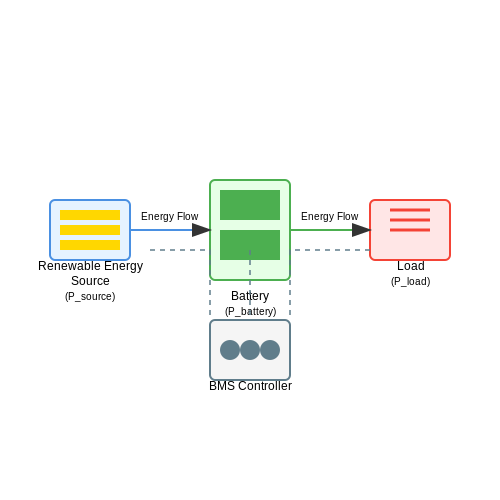
6.2 Advancements in Battery Technologies
In recent years, the landscape of battery technologies has experienced a profound transformation, paving the way for improvements in energy storage and power delivery systems essential for modern applications, ranging from electric vehicles to renewable energy integration. This section explores key advancements in battery technologies that impact Battery Management Systems (BMS). One of the most notable strides is the evolution of lithium-ion battery chemistries. Innovations such as lithium iron phosphate (LiFePO4) and lithium nickel manganese cobalt oxide (NMC) have enhanced not just the energy density but also safety profiles significantly. LiFePO4, for example, offers greater thermal stability compared to traditional lithium cobalt oxide (LCO) counterparts, reducing the risk of thermal runaway, a critical consideration for BMS design. Moreover, the exploration of solid-state batteries is generating substantial excitement. Solid-state technology replaces the liquid electrolyte found in conventional lithium-ion batteries with a solid electrolyte, potentially doubling energy densities and increasing safety margins. This approach minimizes flammability risks associated with liquid electrolytes while allowing for more compact battery systems. The integration of solid-state batteries will necessitate more sophisticated BMS algorithms to manage diverse operating conditions and ensure safe charge/discharge cycles. Following the trend of higher energy density, researchers are investigating lithium-sulfur (Li-S) batteries as a promising alternative, thanks to their theoretical capacity exceeding that of lithium-ion batteries. Although challenges such as polysulfide dissolution and cathode structural degradation remain, ongoing advancements in cathode materials and novel electrolytes are being developed to overcome these limitations. A robust BMS will be critical in addressing these issues through real-time monitoring and adaptive control strategies. As battery technology progresses, there is an increased emphasis on sustainability. This shift not only pertains to the sourcing of materials but also to battery lifecycle management. Recycling processes are being refined, and secondary battery applications are gaining traction. An effective BMS must now incorporate functionalities that facilitate battery reusability and end-of-life recyclability, contributing to a circular economy. Furthermore, the integration of machine learning and artificial intelligence in BMS is becoming increasingly important. By utilizing large datasets from battery operating conditions, machine learning algorithms can predict battery degradation, optimize charge cycles, and enhance battery health management. This predictive capability enables better performance forecasting and extends the lifespan of battery packs. In summary, the advancements in battery technologies herald a new era for Battery Management Systems, characterized by innovative chemistries, solid-state developments, sustainability efforts, and the infusion of AI. Engineers and researchers are called to address these emerging demands by creating BMS capable of managing the complexities introduced by these sophisticated energy storage solutions, ensuring safety, reliability, and sustainability in the energy ecosystem.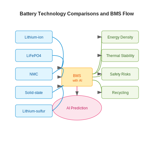
6.3 Role of Artificial Intelligence in BMS
As Battery Management Systems (BMS) evolve to meet the increasing demands of modern energy storage applications, the integration of Artificial Intelligence (AI) is becoming paramount. AI enhances BMS capabilities through predictive analytics, optimization algorithms, and real-time data processing. These advancements not only improve battery performance but also extend the lifespan of batteries significantly.
Enhancing Predictive Maintenance
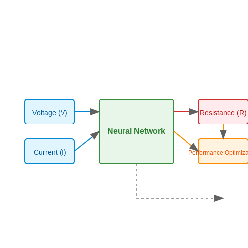
AI algorithms can analyze historical data and detect patterns that are indicative of battery degradation. By utilizing methods such as regression analysis and neural networks, AI can predict failure points before they occur. For example, a neural network trained on voltage, current, and temperature data could foresee potential issues and activate preventative measures in real-time.
Where
- R is the resistance,
- V is the voltage, and
- I is the current.
This resistance equation forms the fundamental basis for understanding battery health metrics. When integrated with AI, BMS can adaptively adjust operating conditions based on predicted resistance changes, thereby optimizing performance.
Optimizing Battery Lifespan and Efficiency
AI systems are equipped with machine learning algorithms that can assess various operational parameters to determine optimal battery usage patterns. These include:
- Charging cycles
- Discharge rates
- Temperature profiles
For instance, AI can modify charging strategies based on historical data and current state-of-charge (SOC) to minimize wear on battery cells, effectively prolonging their operational life. Techniques such as reinforcement learning can dynamically adapt charging profiles to suit fluctuating energy demands.
Case Study: AI in Electric Vehicle Batteries
Electric vehicles (EVs) serve as a prime example of where AI and BMS converge. Companies like Tesla utilize advanced algorithms to optimize the entire battery lifecycle. By analyzing data from millions of vehicles, these AI systems continuously refine battery usage strategies and learn from real-world performance, leading to improvements in energy density and charging times.
Moreover, the implementation of AI-driven BMS in EVs also supports features such as:
- Smart grid integration
- Real-time battery status monitoring
- Automated load balancing with renewable energy sources
Challenges and Future Directions
Despite the clear benefits, integrating AI with BMS is not without challenges. Issues related to data privacy, algorithm transparency, and the need for continuous data collection pose significant hurdles. Furthermore, would-be practitioners must ensure that the chosen AI models are explainable, facilitating trust and understanding among users.
Looking forward, research should focus on developing robust AI frameworks capable of working under varying operational conditions while ensuring safety and reliability.
In conclusion, the integration of Artificial Intelligence into Battery Management Systems represents a significant leap forward, promising enhanced performance, reliability, and longevity in energy storage technologies.
7. Academic Journals and Papers
7.1 Academic Journals and Papers
- MDPI Energies Journal — This journal covers topics related to battery management systems, including advancements in energy storage and control methods. It frequently publishes papers on BMS design, analysis, and optimization strategies.
- Journal of Power Sources — Offers comprehensive research articles on battery technologies and their management systems, focusing on both fundamental and applied aspects related to energy sources.
- Energy Storage Materials by Wiley — This journal provides insights into the materials science aspects of energy storage, with papers discussing innovative BMS techniques for various battery types and applications.
- IEEE Transactions on Energy Conversion — Features articles on the technology and methodologies related to energy conversion systems, including cutting-edge BMS approaches for efficiency and performance enhancement.
- Journal of Energy Storage — Publishes studies on energy storage solutions, particularly focusing on advancements and innovations in the management of energy storage systems, including batteries.
- International Journal of Electronics — Journals contributing technical papers focusing on electronic innovations, including research on BMS technologies, algorithms, and system integration.
- Advanced Energy Materials — Publishes high-impact research articles on material science breakthroughs and innovations that impact energy systems, including efficient battery management strategies.
7.2 Books on Battery Management Systems
- Battery Management Systems: Design by Modelling — This comprehensive resource offers an in-depth exploration of the design and modeling of Battery Management Systems, providing insights into the mathematical and simulation methods used to optimize battery performance.
- Battery Management Systems: Accurate State-of-Charge Indication for Battery-Powered Applications — Focused on accurate state-of-charge indication, this book covers advanced techniques in battery management, including algorithms and innovations in electronic design for battery optimization.
- Advanced Battery Management Technologies for Electric Vehicles — This book highlights the critical role of BMS in electric vehicles, exploring cutting-edge technologies, challenges, and solutions in BMS design and implementation for automotive applications.
- Battery Management Systems: Theory and Practice — Offering a balanced mix of theory and real-world application, this book delves into the practical aspects of BMS, including hardware design and control strategies.
- Battery Management Systems for Large Lithium Ion Battery Packs — This specialized text addresses the unique challenges associated with large lithium-ion battery packs, focusing on safety, performance, and lifecycle management strategies in BMS.
- Battery Management Systems for Electric Vehicles: Power Systems Diagnostics — Covering diagnostics, this book provides a detailed exploration of the BMS in electric vehicles, emphasizing fault detection, system reliability, and preventative maintenance protocols.
- The Handbook of Batteries — A comprehensive resource for battery technology, including BMS, this handbook covers materials, design, and system considerations essential for developing advanced battery technologies.
Online Resources and Tutorials
For those seeking to deepen their understanding of Battery Management Systems (BMS), a plethora of online resources and tutorials are available that cater specifically to advanced users like engineers, physicists, and graduate students. These resources cover theoretical concepts, practical implementations, and the latest research findings, offering an all-encompassing learning experience.- Battery Management System Design — A comprehensive guide covering the essential design aspects of BMS with practical examples and in-depth explanations of key features. Suitable for engineers and designers working on advanced battery solutions.
- TI Training on Battery Management Systems — Texas Instruments offers detailed video tutorials and lectures on state-of-the-art BMS technologies, discussing design strategies and implementation specifics beneficial for researchers and developers.
- Coursera BMS Course — This online course provides a detailed dive into BMS fundamentals, algorithms, and applications, designed by experts for learners looking to specialize in battery technologies.
- edX Course on BMS — Hosted by leading universities, this course offers an advanced overview of BMS principles, covering theoretical foundations, the latest research, and technological advancements.
- Battery University YouTube Channel — Offers a collection of videos discussing various aspects of battery management and technology, providing insights into both theoretical and practical implementations.
- Power Electronics News — A specialized portal providing news, case studies, and cutting-edge research articles related to power electronics and BMS, ideal for keeping up-to-date with industry trends.
- Academic Earth BMS Lectures — Features a series of lectures discussing battery management technologies, focusing on both emerging and established methodologies in the field.
- ResearchGate Journal Articles — Access a wide array of peer-reviewed journal articles and publications on BMS research topics that provide a scientific perspective and in-depth studies.