CAN Bus Communication
1. What is CAN Bus?
1.1 What is CAN Bus?
Controller Area Network (CAN) Bus is a robust vehicle bus standard designed to facilitate communication among various microcontrollers and devices without a host computer. This technology was originally developed by Bosch in the 1980s for automotive applications, allowing for communication between various electronic control units (ECUs), which has since proliferated into industrial automation, medical devices, and even maritime applications. The CAN protocol enables reliable, real-time data transmission at high speeds while minimizing wiring complexity.
One of the defining features of CAN Bus is its multi-master configuration, which allows multiple nodes to transmit messages without requiring a single point of control. This is achieved through a method called Carrier Sense Multiple Access with Collision Detection (CSMA/CD), enabling efficient data prioritization and message handling in a networked environment. In a CAN Bus system, each device attaches to the same two-wire bus—often referred to as CAN High (CANH) and CAN Low (CANL)—thus simplifying wiring and reducing costs.
The CAN Bus operates by sending messages rather than addressing particular nodes. Each message carries a unique identifier, which denotes its priority; lower numerical identifiers have higher priority. When a high-priority message is sent while a lower-priority message is in transmission, the higher-priority message "overrides" the lower one, which is then retransmitted once the bus becomes free. This prioritization mechanism is critical in applications where timely data delivery is crucial, such as in automotive safety systems.
Technical Overview
In terms of speed and data transmission rates, CAN Bus typically operates at speeds ranging from 10 Kbps to 1 Mbps. It employs a differential signaling method to reduce noise and increase the reliability of data transmission over long distances, making it a resilient choice for environments with electromagnetic interference. Up to 1,024 devices can be connected to a single CAN network, offering flexibility in system design.
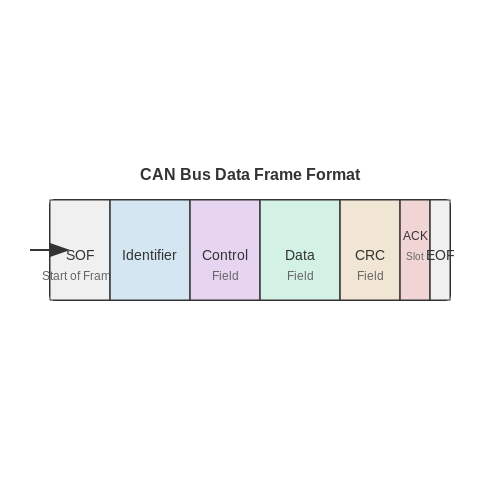
The data frame format is one of the most critical constructs in the CAN protocol, comprising the following elements:
- Start of Frame (SOF): Indicates the beginning of a message.
- Identifier: Sets the priority for the message.
- Control Field: Contains information about the data length and type.
- Data Field: Carries the actual data being transmitted.
- CRC Field: Used for error detection.
- Acknowledgment Slot: Acknowledges the successful receipt of the message.
- End of Frame (EOF): Marks the end of the message.
These components allow for a structured and efficient method of communication, where error handling is a crucial aspect, ensuring that any corrupted messages can be detected and resent, thus maintaining the integrity of the data.
Practical Applications
Beyond automotive machinery, CAN Bus technology finds its applications in various fields, including:
- Industrial Automation: Used for linking sensors, actuators, and control units in complex manufacturing systems.
- Medical Equipment: Supports the interoperability among devices such as imaging equipment and patient monitoring systems.
- Aerospace: Employed in avionics systems to communicate between various flight management components, ensuring reliability and safety.
The choice of CAN Bus can significantly enhance system performance, reduce wiring complexity, and improve overall reliability across various sectors. As technology continues to evolve, so does the relevance of CAN Bus in facilitating the future of interconnected systems.
1.2 History and Development of CAN Bus
The Controller Area Network (CAN) Bus protocol plays a pivotal role in modern automotive and industrial communications. Its history is marked by a series of innovations and adaptations that have shaped its current form, with roots tracing back to the early 1980s. In 1983, Robert Bosch GmbH initiated the development of CAN Bus to address the challenges of communication in automobiles. Emerging from the need for a reliable message-oriented protocol that could handle the complex interconnectivity of electronic control units (ECUs), CAN was designed to facilitate robust data exchanges within noisy environments encountered in vehicles. The original goal was to reduce the wiring needed for communication between ECUs, leading to weight savings and increased reliability. The first version of the CAN specification was introduced in 1986, primarily targeted for automotive applications. This was the first formal recognition of the protocol, establishing a foundation upon which further advancements would be built. The elegant simplicity of CAN's communication model—based on a priority-based message system and effective error detection capabilities—set it apart from existing technologies, allowing for asynchronous data transmission between devices without requiring a central controller. In 1991, the CAN specification was revised to include additional features and enhancements that improved performance. This version, known as CAN 2.0, became widely adopted not only in the automotive industry but also in industrial automation systems, aerospace, and medical equipment. The introduction of both standard (11-bit identifier) and extended (29-bit identifier) formats significantly increased the versatility of the protocol, allowing it to fit various application requirements, from simple sensor data to complex control functions. As the 1990s progressed, CAN Bus technology continued to evolve. The establishment of the CiA (CAN in Automation) organization in 1992 marked a significant step in standardizing CAN-related technologies. This organization worked on enhancing the protocol for use in broader applications beyond automobiles, including CANopen, a higher-layer protocol that supports complex devices and systems through additional services such as device profiles and communication management. The turn of the century saw further advancements with the emergence of CAN FD (Flexible Data-rate), introduced in 2012. The CAN FD protocol expanded the data payload per message and allowed for increased data rates, catering to the rising demands of modern automotive applications, such as advanced driver-assistance systems (ADAS) and autonomous vehicles. The adoption of CAN FD illustrates the ongoing evolution of the protocol to meet the industry's needs. Today, the legacy of CAN Bus is evident in multiple sectors. From automotive networks powering advanced electronics to automation in manufacturing plants, the CAN protocol's design principles continue to uphold its efficacy in facilitating reliable communication in difficult environments. By providing real-time information, it empowers systems that enhance safety, efficiency, and the overall performance of complex electronic systems. As we delve deeper into understanding the intricacies of CAN Bus and its applications, it becomes clear that the historical milestones not only shaped its development but also laid the groundwork for ongoing innovations, ensuring its relevance in future technological advancements.1.3 Applications of CAN Bus Technology
In the landscape of modern communication protocols, the Controller Area Network (CAN) bus has established itself as a cornerstone, particularly in the automotive and industrial automation sectors. Its robust design, characterized by fault tolerance and real-time communication capabilities, enables a myriad of applications.Automotive Industry
The automotive sector is arguably where CAN bus technology shines the brightest. Both light and heavy-duty vehicles extensively use it to enable communication between various control modules, such as the engine, transmission, and infotainment systems. For instance, in modern vehicles, over 70 control units may communicate via CAN, enabling seamless functionality like adaptive cruise control, anti-lock braking systems, and electronic stability programs. The architecture based on CAN bus significantly reduces wiring complexity and weight, contributing to overall vehicle efficiency. Additionally, with the evolving landscape toward autonomy, CAN allows for the integration of advanced driver-assistance systems (ADAS), facilitating real-time data sharing between vehicle components to enhance safety features.Industrial Automation
The industrial automation landscape has also embraced CAN bus technology, particularly in robotics and manufacturing control systems. In an automated factory, different machines and subsystems can communicate vital information through CAN networks, improving efficiency and reducing downtime. For instance, a CAN system can interconnect programmable logic controllers (PLCs) with sensors and actuators, leading to optimized performance in assembly lines. Moreover, the CANopen protocol—a higher-layer protocol adherent to the CAN standard—provides comprehensive support for industrial applications. It allows engineers to implement sophisticated network management features and device profiles, further enhancing interoperability across machinery.Healthcare Applications
In the healthcare sector, the reliability of CAN bus technology facilitates its integration into medical devices, such as imaging machines and surgical equipment. For example, CAN networks allow various imaging systems to communicate without the need for extensive wiring, promoting a compact equipment footprint, which is crucial in operating rooms where space is at a premium. Utilizing CAN bus enables medical devices to achieve real-time data transfer and monitoring—imperative for critical-care applications. This capability is vital for ensuring patient safety, as it enables medical professionals to react swiftly to changes in patient status.Marine and Aerospace Systems
Beyond terrestrial applications, CAN bus technology is also critical in marine and aerospace environments. In aviation, for instance, flight control systems utilise CAN for increased reliability and reduced weight associated with traditional wiring harnesses. The ability to transmit data without substantial delays is essential for maintaining control and safety during flight operations. In marine applications, CAN bus facilitates communication between equipment such as navigation systems, engines, and onboard sensors, improving the operational efficiency of vessels. Additionally, modern yachts and commercial ships are increasingly adopting this technology to enhance crew situational awareness and optimize vessel performance.Smart Building Technologies
As smart buildings become more prevalent, effective communication between building automation systems—such as lighting, security, and HVAC—has become a priority. CAN bus technology can interconnect these systems, allowing for efficient energy management and enhanced occupant comfort. Through the deployment of CAN-controlled devices, building management systems can adjust heating and lighting based on occupancy, significantly reducing energy consumption and operational costs. This integration represents a key innovation in enhancing the sustainability of building operations.Conclusion
The versatility and robustness of CAN bus technology across various sectors demonstrate its vital role established over decades. From automotive applications to healthcare, industrial automation, aerospace, and smart buildings, the ability to ensure reliable communication in real-time signals that CAN bus technology will continue to be at the forefront of innovations in networking. This comprehensive view of applications illustrates not only the technical merit of CAN bus but also highlights its ongoing relevance in addressing the complexities of modern systems. As industries evolve and demand increased connectivity, the principles and applications of CAN technology will undoubtedly remain pivotal in shaping future developments.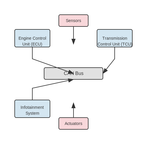
2. Features of CAN Protocol
2.1 Features of CAN Protocol
The Controller Area Network (CAN) protocol, originally developed for automotive applications, has evolved into a versatile communication standard utilized in various fields such as industrial automation, medical instrumentation, and aerospace. The robustness and efficiency of CAN are attributed to several key features, enhancing its reliability and practical applicability.Reliability and Error Management
At the core of the CAN protocol is its ability to ensure high reliability through various error-detection mechanisms. Each node continuously monitors the quality of the messages transmitted over the network. When a node detects a dominant bit (logical '0') or a recessive bit (logical '1') during transmission based on what it sent, it can identify discrepancies associated with bit errors, frame errors, and acknowledgment errors. Some key error management features include:- Bit Monitoring: Each node in the network monitors the signal level on the bus and compares it against its own transmitted bit. A mismatch triggers an automatic error signal.
- Frame Check Sequence (FCS): Each transmitted frame includes a checksum that allows receiving nodes to verify the integrity of the received data.
- Error Frames: If an error is detected, an error frame is transmitted to inform other nodes, prompting them to discard the erroneous message.
High Speed and Efficiency
Advancements in CAN technology have enabled communication speeds up to 1 Mbps in standard CAN networks and even greater in CAN FD (Flexible Data-rate) networks. This capability is achieved through a well-defined message structure that reduces overhead while allowing multiple nodes to transmit simultaneously without collision. Moreover, the use of Non-Return-to-Zero (NRZ) encoding further improves transmission efficiency by ensuring that bit timing is maintained precisely, which is crucial for high-speed data transfer. The priority-based message arbitration algorithm ensures that nodes can send critical messages with minimal delay.Flexible Network Topology
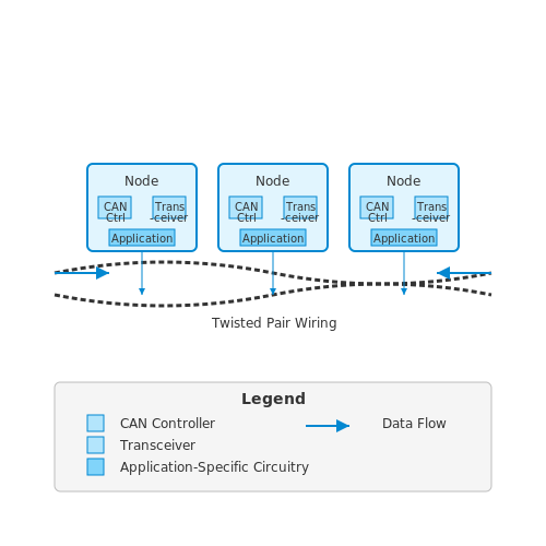
The CAN protocol supports a variety of wiring configurations, most commonly a twisted-pair cable that allows for a multi-master configuration. This flexibility not only simplifies installation and reduces material costs but also enhances the system's resilience against failure. Nodes can be added or removed from the network without necessitating significant downtime, making CAN highly adaptable to changing requirements, such as in automotive environments where sensor types and configurations may evolve.Real-World Applications
The application of the CAN protocol is extensive and spans across several industries. In automotive engineering, CAN is utilized for engine management, safety systems, and infotainment. In industrial automation, it connects various sensors and actuators within machinery, enhancing both efficiency and safety in manufacturing processes. Furthermore, medical devices employ CAN to ensure reliable communication between critical components, while aerospace systems utilize it to manage avionics and engine control systems. Each of these applications exemplifies CAN's inherent advantages in high-reliability environments. In summary, the features of the CAN protocol, notably its reliability, efficiency, flexibility, and broad range of applications, position it as a critical technology in modern communication systems across diverse sectors. As industries continue to evolve, the CAN protocol will undoubtedly play a central role in enabling increasingly complex inter-device communications.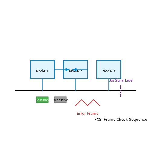
2.2 Data Frame Structure
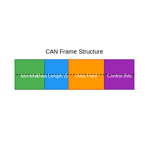
The Controller Area Network (CAN) bus communication system has become a critical protocol in automotive and industrial applications due to its simplicity, fault tolerance, and efficiency. At the heart of this protocol lies the data frame, which is crucial for message transmission between nodes. Understanding the structure of a CAN data frame is fundamental for developing applications that rely on the protocol. The CAN data frame consists of several key components, each serving a vital role in ensuring effective communication. A typical CAN data frame can be broken down into the following fields:Components of a CAN Data Frame
To facilitate a comprehensive understanding, let's enumerate the main components:- Start of Frame (SOF): A single dominant bit that indicates the beginning of the frame.
- Identifier: A unique identifier (11 or 29 bits) that determines the priority and the source of the message.
- Control Field: This contains information like the data length code (DLC), which indicates the size of the data being transmitted.
- Data Field: The actual data being transmitted, with a length of 0 to 8 bytes.
- CRC Field: A 15-bit cyclic redundancy check value that validates the integrity of the message.
- Acknowledge (ACK) Field: This field indicates whether the received frame was accepted, containing a single bit.
- End of Frame (EOF): A sequence that signals the end of the data frame.
Data Frame Structure Visualization
To visualize the structure of a CAN data frame, consider the following representation, where each component is clearly identified: svg This visual representation illustrates how the various components fit together within a single data frame. Each field plays a distinct role in ensuring that the data is transmitted accurately and efficiently.Real-World Relevance
Understanding the structure of the CAN data frame is not merely an academic exercise; it has significant implications in real-world applications. For instance, in automotive systems, where unambiguous communication between multiple electronic control units (ECUs) is paramount, a well-structured CAN frame ensures quick data exchange and responsiveness. Moreover, in industrial applications, such as robotics and automation systems, a robust CAN data frame structure allows for seamless integration of multiple devices, fostering an interconnected environment that enhances operational efficiency. In summary, mastering the CAN data frame structure equips engineers and researchers with the necessary knowledge to design, implement, and troubleshoot systems reliant on this versatile communication protocol. Understanding each component's role ultimately leads to more effective application development and innovation in fields that leverage the CAN bus system.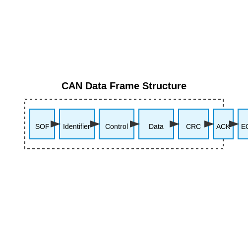
2.3 Error Detection Mechanisms
In the realm of Controller Area Network (CAN) bus communication, ensuring data integrity is critical. The CAN protocol incorporates multiple error detection mechanisms that safeguard against transmission errors, which can arise from various sources such as electromagnetic interference, bit-shifting, and noise within the physical layer. This section delves into the key error detection techniques utilized in CAN, reinforcing the reliability of data transmission.
Bit Error Detection
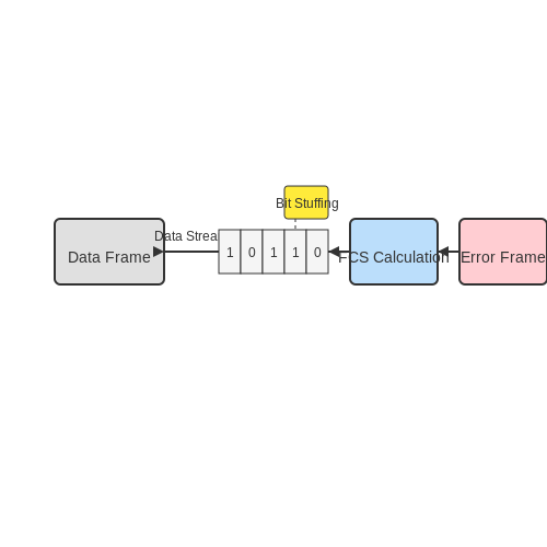
The CAN protocol employs bit stuffing as its primary technique for bit error detection. In this process, a sequence of five consecutive bits of the same value is followed by the opposite bit. This is done to ensure that the receivers can synchronize correctly with the data stream. If a receiver detects more than five consecutive bits, it recognizes it as a potential error. After the sender encodes a sequence, the receiver decodes it, validating its accuracy through a margin of error established during the transmission.
Frame Check Sequence (FCS)
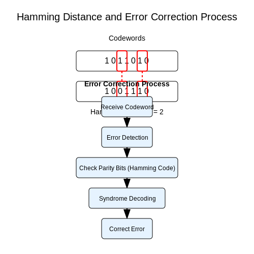
A more sophisticated form of error detection is the Frame Check Sequence (FCS), utilizing a 15-bit cyclic redundancy check (CRC). The sender computes a CRC value based on the entire data frame, appending it to the frame before transmission. The receiver subsequently recalculates the CRC on the received data and compares it to the attached FCS. If the two values do not match, an error is detected.
This method serves two purposes: it detects errant bits and helps in identifying the precise location of the error, thus facilitating recovery processes if necessary. The effectiveness of CRC in detecting errors lies in its ability to catch all single-bit errors and most burst errors, making it a robust choice for CAN communications.
In the equation above, \( d_i \) represents the data bits and \( P(x) \) is the polynomial used for CRC calculations.
Error Frame and Error Handling
In addition to CRC, the CAN protocol incorporates an error frame mechanism which is triggered whenever a node detects a transmission error. This error frame consists of six dominant bits followed by eight recessive bits, effectively signaling to other nodes that an error has occurred. By generating this frame, the system alerts all nodes in the network to discard the erroneous message and thus maintain system integrity.
Moreover, the CAN protocol recognizes two types of errors: transmission errors and reception errors. When an error is detected, the node responsible can transition to an error state to limit its influence on the network. This self-regulation helps prevent cascading failures and ensures that the communication remains reliable even in the presence of errors.
Practical Applications of Error Detection in CAN
The significance of these error detection mechanisms can be observed in real-world applications. For instance, in automotive systems where CAN is extensively used for communication between various electronic control units (ECUs), maintaining data integrity is critical for the operation of safety features and advanced driver-assistance systems (ADAS).
In more industrial contexts, such as factory automation, the reliability provided by CAN's error detection can be linked to ensuring uninterrupted operations. Here, the cost of downtimes due to communication errors can be significantly mitigated by the prompt detection and correction capabilities embedded within the CAN protocol.
Thus, the combination of bit stuffing, CRC, and error frames forms a formidable suite of tools that enhance the robustness of CAN bus communications, crucial for both automotive and industrial applications.
3. Electrical Characteristics
3.1 Electrical Characteristics
The Controller Area Network (CAN) bus has become a standard in industrial and automotive systems due to its robust communication capabilities. Understanding the electrical characteristics of CAN is vital for engineers and researchers in designing reliable systems. The essential parameters that govern the electrical interface of CAN communication include voltage levels, signal integrity, and transmission rates, each of which contribute significantly to the overall performance of the network.Voltage Levels
At its core, CAN utilizes a differential signaling method across a twisted pair of wires. This signifies that the CAN bus transmits signals based on voltage differences between the two lines - CAN High (CANH) and CAN Low (CANL). Under normal operating conditions, the voltage levels are as follows: - The dominant state, indicated by the sending of '0', is characterized by a signal where the voltage on CANH is approximately 2.5V to 3.5V, while CANL holds a value around 1.5V to 2.5V. - Conversely, the recessive state, indicative of '1', flips these conditions; thus, CANH typically ranges between 1.0V to 1.5V and CANL between 2.5V to 3.5V. These specifics allow for robust signal transmission while mitigating noise, as any voltage fluctuation due to interference is detected relatively easily due to the differential nature of the signaling.Signal Integrity and Rise/Fall Times
The integrity of the transmitted data hinges on several interrelated electrical specifications, particularly the rise and fall times of signals. CAN protocol stipulates that the maximum rise and fall times must be around 20% of the bit time to maintain signal integrity. This characteristic ensures that transmitted data adequately complies with required standards, minimizing signal distortion due to voltage changes. In practical systems, maintaining an impedance matching is also crucial as reflected signals can severely affect communication quality. The typical CAN bus operates with a characteristic impedance of 120 ohms, and it is essential that all nodes maintain this impedance to avoid reflections that can corrupt messages.Transmission Rates and Bit Timing
The speed at which data passes through a CAN bus interface is quantified as the bit rate, commonly set at various standards such as 125 Kbps, 250 Kbps, and up to 1 Mbps. Choosing the appropriate bit rate is vital as it directly impacts the transmission distance and network reliability. Shorter segments of wire can support higher bit rates; however, this advent comes at the cost of increased susceptibility to errors. The bit timing configuration is also essential, as this governs how bits are sampled against time. The configuration typically involves setting a bit time divided into segments—sync, propagation, phase buffer, and data segment. Each segment serves a specific purpose and must align perfectly to enhance the reliability of data reception.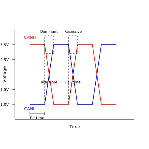
3.2 Wiring and Topology
The Controller Area Network (CAN) bus protocol is a robust vehicle bus standard designed for reliable communication in noisy environments. A critical aspect of implementing CAN bus systems involves understanding how wiring and topology contribute to performance, reliability, and scalability. In this section, we will discuss the wiring requirements, the topology configurations, and their practical implications in real-world applications.
Wiring Requirements
To ensure effective transmission of data over a CAN bus, the choice of wiring material and configuration is vital. The standard wiring typically utilizes twisted-pair cables, which greatly reduce electromagnetic interference (EMI). The characteristics of these cables are crucial:
- Impedance: The cables should have a characteristic impedance of around 120 ohms. Mismatched impedance can lead to reflections and signal degradation.
- Capacitance: Low-capacitance cables (~30 pF/m) help in preserving signal integrity over long distances.
- Shielding: Shielded twisted-pair (STP) cables are advantageous in highly electrically noisy environments, reducing the likelihood of external interference.
Wiring length also plays a critical role in a CAN system. For a standard CAN network operating at typical speeds (up to 1 Mbps), the maximum cable length without repeaters is defined by the following empirical relationship:
Consequently, for a CAN bus operating at 1 Mbps, the maximum length can reach up to 100 meters. This equation illustrates how baud rate limits the distance, emphasizing the importance of selecting the appropriate baud rate based on network requirements.
CAN Bus Topology
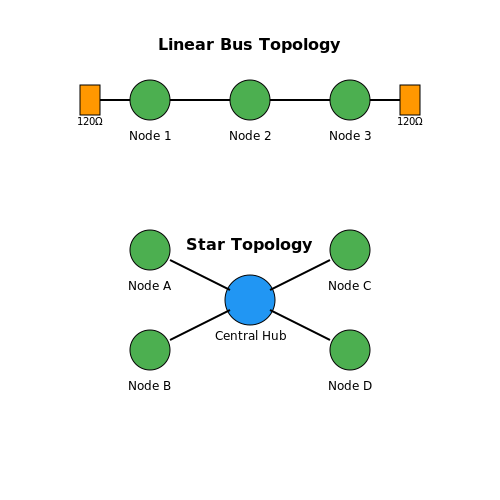
The physical layout of the CAN bus, often referred to as the topology, significantly affects the network performance. The most common topologies used in CAN bus implementations include the linear bus and the star topology. Each has its advantages and applications:
Linear Bus Topology
In the linear bus topology, nodes are connected along a single communication line. This design is cost-effective and straightforward to implement. However, it is essential to ensure that the network ends are terminated properly with 120-ohm resistors to prevent signal reflections. The configuration can be visualized as follows:
While the linear bus is suitable for smaller networks, it has limitations regarding fault tolerance; a break in the bus will disrupt communication across the entire network.
Star Topology
The star topology, although less common in CAN systems, involves connecting all nodes to a central hub or switch. This layout allows for better fault tolerance since a failure in one branch does not affect the entire network. However, it typically incurs higher installation costs and can introduce latency due to the central point of communication. The star topology can be depicted as:
Practical Applications and Considerations
Understanding wiring and topology is crucial for various applications of CAN bus, especially in automotive, industrial automation, and aerospace. In automobiles, CAN bus facilitates communication between critical systems such as the engine control unit and safety features like anti-lock braking systems (ABS).
From a practical standpoint, engineers must carefully assess the physical configuration, cable quality, and layout to ensure the optimal functioning of CAN networks. Future advancements might include hybrid topologies or enhanced wiring materials to further improve performance and resilience against interference.
In essence, selecting the right wiring scheme and topology forms the foundation of any successful CAN bus implementation, making it a vital consideration in the design process.
3.3 Termination and Signal Integrity
In the realm of Controller Area Network (CAN) Bus communication, maintaining signal integrity is paramount for ensuring reliable and accurate data transmission. One critical aspect of preserving signal integrity is the proper termination of the CAN Bus. This subsection will deeply explore the significance of termination, the mechanisms of signal degradation, and the practical implications of these concepts.
Understanding Termination
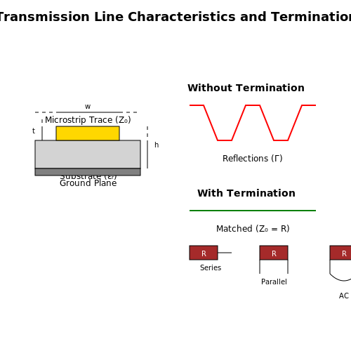
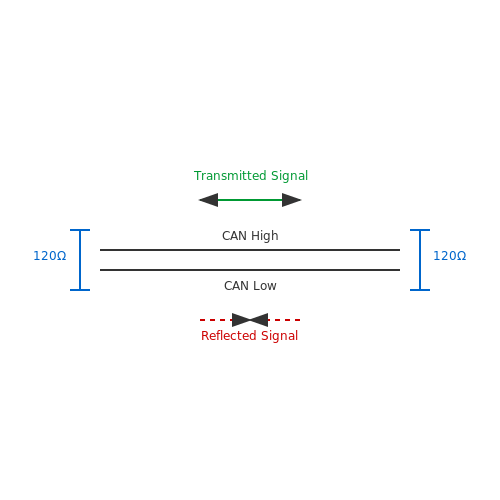
Termination refers to the practice of placing resistors at both ends of the CAN Bus to prevent signal reflections, which can distort the transmitted signals. This is particularly important in a differential signaling environment like CAN, where signals are transmitted as voltage differences between two wires (CAN High and CAN Low).
The standard termination resistor value for a CAN Bus is typically 120 ohms. This value is determined by the characteristic impedance of twisted pair cables commonly used in CAN networks. Placing equal resistors at both ends of the bus ensures that the signal sees a load that matches its inherent impedance, effectively minimizing reflections that can lead to data errors.
Signal Integrity and Its Challenges
Signal integrity encompasses various phenomena that can affect the quality and reliability of transmitted signals, including:
- Reflections: When signals encounter a change in impedance along the transmission line, some of the signal is reflected back towards the transmitter, causing interference.
- Attenuation: As signals travel along the cable, they lose strength due to resistance in the wire, leading to weakened signals that may not be recognized by receivers.
- Crosstalk: In multi-wire setups, signals from one wire can induce voltage in adjacent wires, causing further degradation of the intended signal.
The combination of reflections and attenuations is typically visualized in a time domain reflectometer (TDR) graph, which shows the behavior of signal waves as they traverse through the bus. A well-terminated bus will show clear signal integrity without oscillations indicative of reflections.
The Role of Cable Length and Data Rate
The physical length of the CAN Bus and the data rate employed are crucial factors in determining the effectiveness of termination. Longer cable lengths and higher data rates exacerbate the issues of signal integrity:
- Data Rate: The CAN protocol supports various baud rates, typically ranging from 10 kbps to 1 Mbps. As speed increases, the time it takes for signals to travel becomes significant relative to the time between signal transitions, increasing the risk of reflection interference.
- Cable Length: The maximum recommended length for a standard CAN Bus is 40 meters at 1 Mbps. Exceeding this length activates more pronounced signals degradation due to both attenuation and increased reflection occurrences.
Practical Application: CAN Bus Systems
In practical scenarios, such as automotive applications, termination and signal integrity are critical as the bus can be subject to harsh environmental conditions, including temperature fluctuations and electromagnetic interference. Proper implementation of 120-ohm termination resistors, strategic bus layouts that minimize cable lengths, and the careful selection of cable types contribute to maintaining robust communication systems.
In summary, recognizing the importance of termination in the context of CAN Bus communication is essential for designing reliable systems. Engineers and designers must adhere closely to established standards and conduct thorough testing to ensure that signal integrity is preserved. Failure to address these considerations can lead to system failures, communication errors, and additional costs.
4. Message Prioritization and Arbitration
4.1 Message Prioritization and Arbitration
The Controller Area Network (CAN) bus is integral to modern automotive and industrial communications, enabling robust and deterministic packet transmission between nodes. A crucial aspect of maintaining the integrity and efficiency of this network lies in the techniques of message prioritization and arbitration. Understanding these foundational concepts is essential for engineers and researchers developing systems that utilize CAN protocols.
Understanding Message Prioritization
In CAN bus communication, each message is assigned a unique identifier, referred to as a CAN identifier (CAN ID). This ID not only identifies the message's source and purpose but also determines its priority during data transmission. Lower numerical values of the CAN ID equate to higher priority. For instance, a message with a CAN ID of 11 will have a higher priority than one with an ID of 20. The prioritization scheme effectively ensures that critical messages are transmitted in a timely manner, especially during instances of network congestion.
Arbitration Process
To maintain seamless communication and avoid data collisions on the bus, CAN employs a method called *arbitration*. Arbitration occurs when multiple nodes attempt to transmit messages simultaneously. Instead of relying on a master-node structure, CAN uses a distributed approach wherein all nodes are capable of initiating transmission.
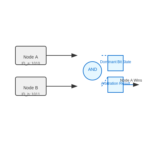
The arbitration mechanism works based on the identifier's value. During transmission, each node sends its bits onto the network one by one. The bus utilizes a logical AND operation to determine which node's message has the highest priority. If two nodes transmit simultaneously, the one with the lower priority ID will detect that the dominant level is present (a logical '0' is dominant over a logical '1') and thus will cease transmission, allowing the higher-priority message to take precedence.
Mathematical Representation of Arbitration
To analyze the arbitration mathematically, consider the arbitration of two nodes attempting to send messages with CAN IDs \(ID_a\) and \(ID_b\). Assuming \(ID_a < ID_b\) implies higher priority, the results of the arbitration can be evaluated:
This straightforward comparison illustrates the deterministic nature of CAN arbitration. The outcome determines which node will gain access to transmit data when conflicts arise, thus ensuring that messages are sent according to their priority levels.
Practical Applications
CAN bus communication, with its message prioritization and arbitration system, is particularly advantageous in various applications. In automotive systems, for example, messages related to engine performance or safety mechanisms (e.g., airbags) are given higher priority over less critical information like infotainment controls. This capability minimizes risks and optimizes performance by ensuring that essential data transmission takes precedence in real-time scenarios.
Moreover, industries relying on automation and control systems deploy CAN due to its resilience against noise and its fault-tolerant characteristics. Whether in robotics, manufacturing, or even medical devices, understanding and leveraging message prioritization and arbitration can lead to significant advancements in efficiency and reliability.
In summary, the mechanism of message prioritization and arbitration in CAN bus communication enables efficient, reliable, and deterministic communication patterns, vital in any critical control environment.
4.2 Sending and Receiving Messages
Understanding how to send and receive messages over a Controller Area Network (CAN) bus is pivotal for engineers and researchers working on automotive systems, industrial automation, or robotics. The CAN protocol, originally developed for automotive applications, enables multiple electronic devices to communicate without complex centralized control. This subsection delves into the essential mechanisms for effective CAN message transmission and reception.
Message Structure
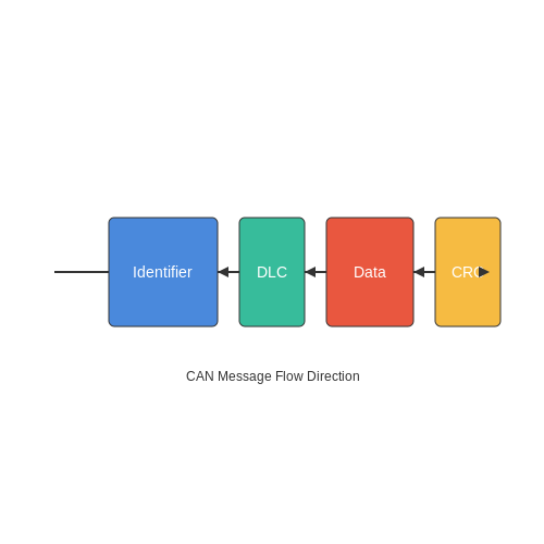
CAN messages are defined by a specific structure, which includes several key components. At its core, each message comprises:
- Identifier: A unique value that determines message priority.
- Data Length Code (DLC): Indicates the number of data bytes in the message, ranging from 0 to 8.
- Data: The actual message content, which can carry any type of information needed for communication.
- CRC: A checksum that facilitates error detection, ensuring data integrity during transmission.
For example, a typical CAN message can be structured as follows:
Sending Messages
To initiate communication, a node must format a message according to the CAN protocol specifications. The process of sending messages involves:
- Preparing the Message: The node constructs the message with the appropriate identifier, length, and data content.
- Transmitting the Message: Once formatted, the message is sent to the CAN bus. The physical layer of the CAN protocol utilizes differential signaling to transmit data, enhancing noise immunity.
This method allows for simultaneous message broadcasts and prioritizes higher-priority messages to ensure timely data delivery. To assess the network load and manage the message transmission effectively, the CAN protocol implements a bus arbitration mechanism.
Receiving Messages
Upon transmission, each node on the CAN network is responsible for monitoring the bus and receiving messages. The reception process comprises the following steps:
- Monitoring the Bus: Nodes continuously listen to the CAN bus for incoming messages that match their identifier.
- Receiving Valid Messages: Upon detecting a message, the node checks the identifier and CRC to verify message integrity.
- Processing the Data: Once a valid message is received, the node processes the data according to its function within the system.
This decentralized approach not only enhances the flexibility of communication but also minimizes the need for complex wiring harnesses that often characterize traditional communication systems.
Practical Applications
The versatility and reliability of CAN bus communication have made it a staple in various industries. In automotive applications, it efficiently manages communication among the engine control unit, transmission, and other onboard systems. Beyond vehicles, CAN is also prevalent in:
- Industrial Automation: Facilitating communication between sensors and actuators in manufacturing environments.
- Robotics: Enabling data exchange between robotic components and controllers for seamless operation.
This subsection has outlined the necessary components and processes for sending and receiving messages over a CAN bus, highlighting its operational significance across diverse technological domains.
4.3 Message Filtering and Acceptance
As the Controller Area Network (CAN) has become a staple in automotive as well as industrial applications, the management of message flow through the network has emerged as a critical area of focus. Specifically, the mechanisms behind message filtering and acceptance play pivotal roles in organizing the data being transmitted across CAN networks. This capability is especially vital given the limited bandwidth available in a multi-node system, ensuring that nodes only process messages that are relevant to their respective functions.
Understanding Message Acceptance
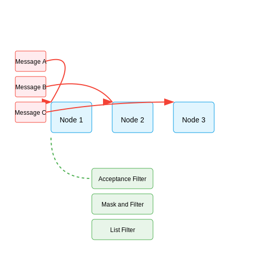
Message acceptance refers to the process by which a receiving node determines whether to accept a received message. The acceptance criteria typically hinge on the message identifier, which can take the form of either a standard identifier (11 bits) or an extended identifier (29 bits). A critical aspect of this process is the Acceptance Filter, which every node employs to evaluate incoming messages against predefined criteria.
The basic operation of message acceptance can be visualized as follows: imagine a postal system where each piece of mail (message) is accompanied by an address (identifier). Each mailbox (node) has a list of addresses it will accept mail from. Only messages matching these criteria are "delivered" for further processing.
Types of Acceptance Filters
There are primarily two types of acceptance filter methods utilized in CAN systems:
- Mask and Filter: This method utilizes a combination of a filter and a corresponding mask, allowing multiple identifiers to be accepted with varying degrees of granularity. The mask determines which bits of the identifier are relevant for acceptance, effectively streamlining decision-making.
- List Filter: This is a more straightforward approach where specific identifiers are directly listed for acceptance. While simpler to implement, it is less adaptable compared to the mask and filter method.
Practical Relevance and Applications
The practical implications of efficient message filtering are significant, particularly in applications where real-time processing is essential, such as in automotive safety systems. For instance, an Anti-lock Braking System (ABS) may need to receive messages from various sensors while ignoring irrelevant data that could slow down system response time. Without effective filtering, data overloading could lead to critical system failures, emphasizing the necessity of these mechanisms in design.
Summary
In summary, the message filtering and acceptance mechanisms in CAN Bus communication are essential components that enable efficient, reliable, and real-time data exchange in complex systems. Understanding how acceptance filters operate—both in terms of their design and practical application—can significantly enhance the robustness and efficacy of CAN-based solutions.
5. CAN Bus Controllers
5.1 CAN Bus Controllers
The Controller Area Network (CAN) bus is an essential protocol widely used in automotive and industrial applications due to its robustness and efficiency. Central to the successful implementation and operation of a CAN bus system are the CAN bus controllers, which function as the brain of the communication network. In this section, we will explore the function, architecture, and implementation of these controllers, providing a detailed overview for advanced readers.
Understanding CAN Bus Controllers
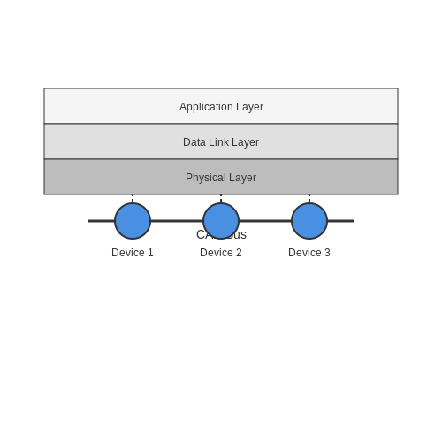
A CAN bus controller is a microcontroller or integrated circuit that manages the transmission and reception of messages over the CAN bus. It encapsulates the lower layers of the OSI model, specifically the physical and data link layers, allowing seamless communication between nodes on the network. The primary responsibilities of a CAN bus controller include:
- Message Framing: Controllers define the structure of CAN messages, ensuring that data formats comply consistently across various devices.
- Error Handling: They implement robust error detection mechanisms such as cyclic redundancy check (CRC) and acknowledge (ACK) bits to maintain communication integrity.
- Priority Management: CAN employs a priority-based system for message arbitration, wherein the controller facilitates the identification of message priority based on the identifier field, allowing higher-priority messages to take precedence.
Architecture of a CAN Bus Controller
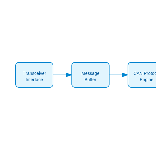
The architecture of a CAN bus controller typically consists of several key components:
- Transceiver Interface: This component interfaces the controller with the physical medium of the CAN network, ensuring proper voltage levels and signal integrity.
- Message Buffer: To manage data flow, controllers use message buffers to temporarily store incoming and outgoing messages, which aids in efficient data transmission and minimizes the risk of message loss.
- CAN Protocol Engine: This hardware module is responsible for implementing the protocol’s rules, including message framing, bit stuffing, and error detection.
For visual clarity, consider a simplified block diagram of a CAN bus controller, illustrating these components and their interconnections. The transceiver, for example, forms a bridge between the controller and the physical bus, while the protocol engine processes the data according to CAN standards.
Examples of CAN Bus Controllers
Several manufacturers provide CAN bus controllers, each with unique specifications and capabilities tailored for different applications. Some of the most recognized controllers include:
- MCP2515: A widely used stand-alone CAN controller that communicates via SPI, suitable for various embedded applications.
- STM32F4 Series: Microcontrollers that include integrated CAN controllers, offering rich processing power along with peripheral functionalities.
- TJA1050: A high-speed CAN transceiver which works seamlessly with CAN controllers to ensure reliable communication.
Practical Applications of CAN Bus Controllers
Understanding CAN bus controllers goes beyond academic interest; these controllers have a broad spectrum of real-world applications. In the automotive industry, for instance, they are integral to vehicular communication systems involving engine management, safety systems, and infotainment. Furthermore, in industrial automation, CAN bus technology can efficiently link sensors and actuators, facilitating real-time data processing and control.
Conclusion
The role of CAN bus controllers is vital in deploying robust communication networks for myriad applications. Their design and implementation dictate not only the efficiency of data exchange but also the overall reliability of the systems they support. As technology continues to evolve, so too will the capabilities and sophistication of CAN bus controllers, paving the way for increased complexity and functionality in interconnected systems.
5.2 Transceivers and Interfaces
The successful operation of a Controller Area Network (CAN) relies heavily on the role of transceivers and interfaces. These components facilitate the physical layer of CAN communication, enabling reliable data transmission in electrically noisy environments typically found in automotive and industrial applications. In this section, we will explore the functionality, types, and implementation of transceivers, as well as the various interfaces they use to connect to different microcontrollers or processing units.
Transceivers: The Heart of CAN Communication
At the core of CAN communication are transceivers that convert digital signals from a microcontroller into the differential signals required for the CAN bus. This differential signaling technique is crucial for minimizing electromagnetic interference from external sources and maintaining data integrity over long cable distances.
A typical CAN transceiver operates by translating the digital logic levels of the microcontroller into voltage levels that represent the dominant (logical '0') and recessive (logical '1') states on the bus. The dominant state is characterized by one CAN line being more positive than the other, whereas in the recessive state, both lines are at the same voltage level.
CAN Transceiver Standards
The CAN transceivers are generally compliant with various standards such as ISO 11898-2, which specifies the physical layer for high-speed CAN networks and sets the limits for signal levels, timing, and electromagnetic compatibility. The study of these standards is essential for ensuring compatibility across different devices and applications. Popular models like the MCP2551 and TJA1040 are commonly used due to their robust performance in automotive environments.
Key Characteristics of Transceivers
Several key characteristics define the effectiveness of CAN transceivers:- Data Rate: Most transceivers support data rates up to 1 Mbps, but variations exist for low-speed CAN systems.
- Voltage Levels: The typical voltage levels for the CAN bus are 0 to 5V, with thresholds for dominant/recessive determined by the transceiver specifications.
- Fault Tolerance and Robustness: CAN transceivers exhibit high noise immunity and can allow for a single-point failure in a linked CAN network, maintaining the integrity of communication.
Interfaces: Bridging the Transceiver and Microcontroller
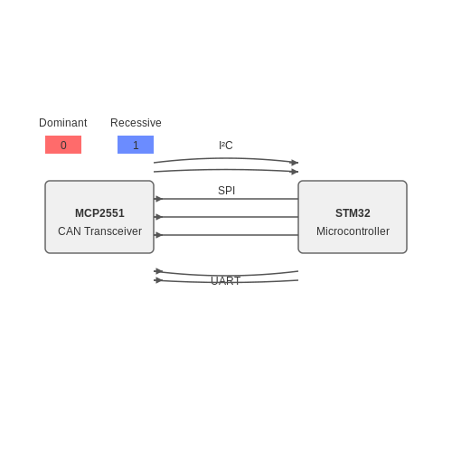
While the transceiver is critical for transmitting data onto the physical bus, it requires a suitable interface to connect with a microcontroller or processor. This interface often comes in the form of a serial peripheral interface (SPI), inter-integrated circuit (I²C), or universal asynchronous receiver–transmitter (UART).
Common Interface Types
Several approaches exist for interfacing CAN transceivers with microcontrollers:
- SPI Interface: Many high-speed applications utilize SPI for rapid data transfer between the microcontroller and the CAN controller, allowing for high bandwidth in real-time applications.
- I²C Interface: Used for lower-speed applications, I²C offers a simple two-wire connection, which can be beneficial in systems with multiple peripherals that share the same bus.
- UART Interface: This is often selected when ease of implementation is prioritized. UART communication can simplify the task of initializing and configuring CAN devices through readable, serial communication.
Practical Implementation
In deploying CAN communication systems, understanding the selection criteria for transceivers and their interfacing mechanisms is essential. For example, designing a robust automotive CAN network requires careful consideration of signal integrity, desired communication speed, and compatibility with existing systems. Engineers often run simulations using tools such as SPICE to validate their designs prior to implementation, factoring in worst-case scenarios to ensure reliability.
As an illustration, consider integrating a Microchip MCP2551 transceiver with an STM32 microcontroller via an SPI interface. In this arrangement, the STM32 can transmit and receive messages efficiently while benefiting from high data rates and lower electromagnetic interference, making it suitable for complex applications in modern automotive systems.
In summary, understanding the nuances of transceivers and interfaces in CAN bus communication is crucial for developing reliable, efficient, and fault-tolerant distributed networks. As we delve deeper into CAN protocols and applications in subsequent sections, the interplay of transceiver technology and interfacing will continue to highlight its importance in the realm of industrial and automotive communication systems.
5.3 Programming CAN Bus Applications
The Controller Area Network (CAN) Bus is a robust vehicle bus standard designed for reliable communication among various devices without a host computer. As automotive and industrial systems become more complex, programming applications that effectively utilize CAN Bus technology is essential. This section delves into key programming considerations and practical approaches for developing CAN Bus applications.
Understanding the CAN Protocol
Before embarking on programming CAN Bus applications, it is vital to have a solid grasp of the underlying protocol. At its core, CAN uses a messaging format that supports multi-master configurations, meaning that multiple nodes can send and receive messages without prior coordination. Each message consists of an identifier, which determines the priority during message arbitration—a crucial factor for avoiding data collisions.
The primary message types in CAN include:
- Data frames
- Remote frames
- Error frames
- Overload frames
Understanding the structure of these frames is essential for effective programming and communication across the network.
Programming Environments and Tools
Several software environments and libraries are available for developing CAN Bus applications. Most of these tools provide support for CAN interfaces, allowing easy integration with microcontrollers or embedded systems. Some popular options include:
- SocketCAN: A set of open-source CAN drivers and a networking stack for Linux.
- CANopen: A higher-layer protocol for CAN, often used in automation.
- Microchip’s MCP2515: A CAN controller used in various embedded applications.
Choosing the right environment largely depends on the application requirements and existing hardware. It is beneficial to become familiar with the documentation and libraries pertinent to your chosen toolset.
Basic Program Structure
Regardless of the tool, most CAN Bus applications follow a similar structure, which usually includes:
- Initialization of the CAN driver
- Configuration of message filters
- Sending and receiving messages
- Error handling and management
Let’s consider a simple example illustrating the initialization and message sending in C using SocketCAN:
#include
#include
#include
#include
#include
#include
#include
#include
#include

int main() {
    int socketCAN = socket(PF_CAN, SOCK_RAW, CAN_RAW);
    struct ifreq ifr;
    strcpy(ifr.ifr_name, "can0");
    ioctl(socketCAN, SIOCGIFINDEX, &ifr);

    struct sockaddr_can addr;
    addr.can_family = AF_CAN;
    addr.can_ifindex = ifr.ifr_ifindex;
    bind(socketCAN, (struct sockaddr *)&addr, sizeof(addr));

    struct can_frame frame;
    frame.can_id = 0x123; // CAN identifier
    frame.can_dlc = 8;    // Data length
    strcpy((char*)frame.data, "Hello"); // Sending message

    write(socketCAN, &frame, sizeof(struct can_frame));

    close(socketCAN);
    return 0;
}
This example serves as a foundation for further development. The program initializes a CAN socket, configures necessary settings, sends a CAN frame, and finally closes the socket.
Testing and Debugging CAN Applications
Developing effective tests and debugging processes for CAN Bus applications is crucial. Software tools such as CAN analyzers and simulators can be employed to monitor the CAN traffic and diagnose potential issues. Leveraging these tools enables engineers to ensure the integrity and reliability of their communication systems.
Additionally, implementing robust error handling mechanisms is essential to maintain system stability. The CAN protocol defines various error frames which can be utilized for detecting and managing errors in real time.
In summary, programming for CAN Bus applications requires an understanding of the protocol, careful selection of development tools, a structured approach to coding, and diligent testing. As the demand for advanced automotive and industrial communication systems grows, mastering CAN Bus development becomes increasingly relevant.
6. Common Issues in CAN Communication
6.1 Common Issues in CAN Communication
In the realm of Controller Area Network (CAN) communication, engineers and researchers often encounter various challenges that can affect performance and reliability. Understanding these common issues is pivotal for robust system design and implementation. One central aspect of CAN communication is its inherent reliance on a multi-master topology, which enables multiple devices to communicate efficiently over a single bus. However, this decentralized nature also introduces a host of potential complications.Error Handling Mechanisms
To mitigate data integrity issues, CAN systems implement sophisticated error handling protocols. These include hardware and software mechanisms such as automatic retransmission, message acknowledgement, and error counters. The primary types of errors encountered in CAN systems are:- Bit Errors: Occur due to electrical noise or signal distortion, leading to incorrect bit transmission.
- Frame Errors: Triggered when a message does not conform to the defined CAN frame structure, often detected during reception.
- Stuff Errors: Relate to violations of the bit stuffing protocol, where additional bits are inserted to maintain signal integrity.
- CRC Errors: Caused by mismatches in the Cyclic Redundancy Check, indicating potential data corruption.
Bus Termination and Signal Reflection
Another common issue arises from improper bus termination. In CAN, the termination resistors are critical for preventing signal reflections that can lead to data corruption. Typically, a 120-ohm resistor is placed at both ends of the bus. Without this termination, signals may bounce back, creating interference that degrades the clarity of communication. To visualize this, think of a water pipe: if the pipe isn't sealed properly at the ends, the pressure can lead to turbulence, making it challenging for water (data) to flow steadily.Network Load and Bandwidth Limitations
As the number of nodes on a CAN bus increases, the load on the network grows. Each node introduces potential for message collisions, requiring the CAN protocol to dynamically manage access to the bus via a priority-based scheme. However, when too many nodes are attempting to transmit simultaneously, the risk of delays and communication failures increases. For real-world systems, such as automotive networks, maintaining an optimal node count and message frequency can be critical. Engineers must carefully balance these factors to ensure messages are transmitted within the time constraints dictated by the application.Electromagnetic Interference (EMI)
Lastly, environmental factors such as electromagnetic interference can significantly impact CAN communication. Since CAN employs differential signaling to enhance robustness against noise, it is usually resilient; however, extreme EMI from motors or other devices can still lead to erroneous messages. Effective strategies such as shielded cables, twisted pairs, and ensuring adequate grounding can serve as mitigative measures against EMI, preserving the integrity of communication across the network.Conclusion
By recognizing and addressing these common issues—error handling, termination, bandwidth limitations, and EMI—engineers can design more reliable CAN systems. Each challenge presents an opportunity to employ innovative solutions that enhance performance and ensure seamless communication, reinforcing the essential role of robust design principles in modern networked environments. Understanding these nuances not only prepares one for troubleshooting existing systems but also informs the design of future CAN applications, driving advancements in automotive, industrial automation, and beyond.6.2 Using Diagnostic Tools
In the realm of the Controller Area Network (CAN) Bus communication, the role of diagnostic tools is paramount for optimizing performance and ensuring reliability. As engineers and researchers delve deeper into embedded systems, the ability to analyze and debug CAN Bus communication becomes crucial. This subsection explores various diagnostic tools available for CAN Bus communication, emphasizing their functionality and practical usage.
Understanding Diagnostic Tools
Diagnostic tools for CAN Bus come in various forms, ranging from software applications to hardware interfaces. These tools facilitate real-time monitoring, fault detection, and performance optimization by providing insights into the data transmitted over the bus. Some widely utilized tools include:
- CAN Bus Analyzers: These devices capture, decode, and display the messages being transmitted across the network. They can reveal issues such as message collisions or loss of communication.
- Diagnostic Software: Programs like CANalyzer or CANoe serve as comprehensive suites for monitoring, testing, and simulating CAN networks.
- Logic Analyzers: While primarily used for digital signals, logic analyzers can also be configured to analyze CAN signals, providing an additional layer of troubleshooting capability.
Real-Time Monitoring with CAN Analyzers
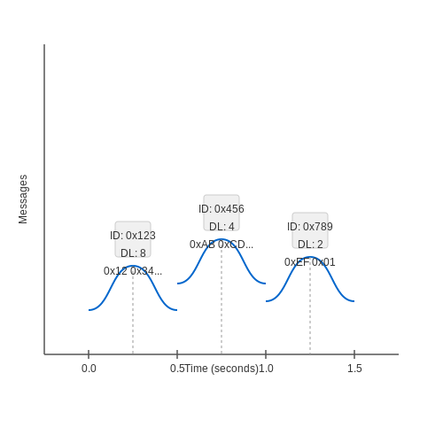
To effectively utilize CAN Bus diagnostic tools, engineers often turn to CAN Bus analyzers. These devices act as intermediaries between the CAN network and a computer, offering a visual representation of data traffic. For instance, a CAN analyzer can display message identification (ID) along with data length and content. It typically interfaces with software that provides graphical user interfaces (GUIs) for further analysis.
One might visualize a CAN Bus analyzer’s data output in a typical waveform view, where each message is represented as a time-sequenced series of bits, with the ID and message painted against a backdrop of time. This provides immediate feedback on whether the bus is operating normally or experiencing issues.
Case Study: Utilizing CANopen Tools in Automotive Diagnostics
In automotive applications, successful implementation of diagnostic tools can enhance both safety and efficiency. Consider the case study of a passenger vehicle employing CANopen—an application layer for CAN that is designed for embedded control systems. Here, engineers used CAN Bus diagnostic tools to isolate faults in the vehicle stability control system. By monitoring CAN messages throughout a driving cycle, they were able to identify erroneous sensor messages, leading to the quick rectification of potential safety hazards.
Interpreting Data Traffic
Understanding the data traffic captured by diagnostic tools allows engineers to swiftly pinpoint communication failures. For example, if an analyzer reveals a regular message pattern but detects an absence of a critical ID, it signifies a fault that may stem from either a disconnected sensor or a malfunctioning module. Therefore, proficient use of diagnostic tools not only expedites troubleshooting but refines overall system design by informing future modifications.
Conclusion
The application of diagnostic tools in CAN Bus communication empowers engineers to proactively address potential issues, enhancing performance and reliability. As the integration of complex systems increases, mastering these tools will be essential for anyone involved in embedded systems, automotive technology, and robotics.
6.3 Analyzing CAN Bus Traffic
Analyzing CAN Bus traffic is essential for understanding how data is transmitted within a network of embedded systems. The Controller Area Network (CAN) protocol is used extensively in automotive and industrial applications due to its robustness and efficiency in transmitting messages among nodes. A clear grasp of CAN Bus traffic offers significant insights into system performance, fault diagnosis, and protocol compliance.
Understanding CAN Frame Structure
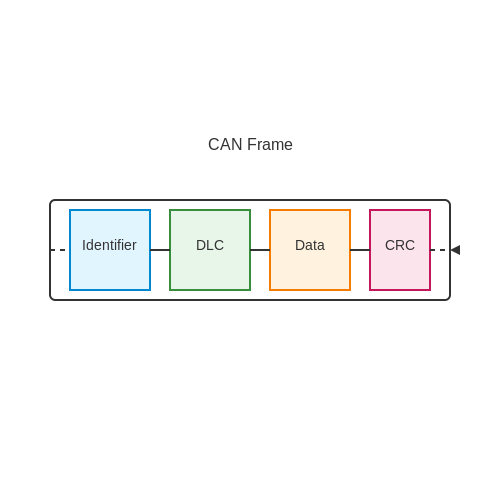
The first step in analyzing CAN Bus traffic involves understanding the structure of CAN frames. A CAN frame contains several fields, including the Identifier, Data Length Code (DLC), Data, and CRC. Below is a brief overview of significant fields:
- Identifier: Specifies the priority of the message, with lower numerical values indicating higher priority.
- DLC: Indicates the number of bytes in the data field (0 to 8 bytes for standard CAN).
- Data: The actual payload transmitted in the frame.
- CRC: Used for error detection, ensuring the integrity of the received messages.
Tools for CAN Bus Traffic Analysis
To effectively analyze CAN Bus traffic, engineers rely on various software tools and hardware devices. Some popular tools include:
- CANalyzer: A professional tool offered by Vector Informatik that allows visualization and logging of CAN messages.
- PCAN-View: A free tool for monitoring CAN traffic and testing communication through an interface to the CAN network.
- Kvaser CANLIB: A library designed for Windows environments, allowing real-time analysis of CAN messages.
These tools enable engineers to monitor live traffic, filter messages, and diagnose errors effectively. As you dive deeper into the analysis, understanding the timing and frequency of messages can lead to further insights into system performance. For instance, high-frequency messages may indicate a critical system operation, while unexpected message delays could signify errors or bottlenecks.
Analyzing Message Patterns and Traffic Load
Once you have established a method for capturing and visualizing CAN data, the next step is to analyze message patterns. This analysis can be approached statistically:
- Message Frequency: Determining how many times a specific message is sent within a given timeframe can reveal operational priorities.
- Traffic Load: Calculating the load on the CAN Bus can help identify potential issues such as network saturation or message collisions. This involves considering the total number of transmitted messages against the bandwidth capacity of the bus.
For more complex systems, message Filtering can also be introduced. Filters can be applied based on identifiers, message types, or any data characteristics, allowing for easier identification of issues related to specific functionalities.
Case Study: Diagnosing a CAN Network Fault
To ground this discussion in a practical scenario, consider a case study involving an automotive manufacturer facing intermittent communication issues among its control modules. Using a CAN traffic analyzer, engineers discovered that a particular module was sending an unusually high number of error frames. Following this leads to:
- Identifying Faulty Hardware: By correlating error frames with physical inspections, faulty connectors were identified.
- Network Optimization: Post-repair, analysis showed significant improvements in frame delivery times and reduced error rates.
This example illustrates the power of effective CAN Bus traffic analysis and its implications for enhancing system reliability. Through systematic analysis, one can not only diagnose faults but also optimize overall network performance.
Conclusion
In conclusion, analyzing CAN Bus traffic is a multifaceted approach that requires technical understanding and the right tools. By focusing on frame structure, utilizing powerful analytical tools, and applying statistical methods, engineers can significantly improve their systems' functioning and reliability.
7. CAN FD and CAN XL
7.1 CAN FD and CAN XL
The Controller Area Network (CAN) has evolved significantly since its introduction, responding to the demands for higher bandwidth and more sophisticated communication methods in automotive and industrial applications. Among the notable advancements in this evolution are the CAN Flexible Data-rate (CAN FD) and CAN XL protocols. These protocols aim to enhance the original CAN, providing higher data rates and increased payloads, thus enabling more complex data exchanges.
The Need for CAN FD
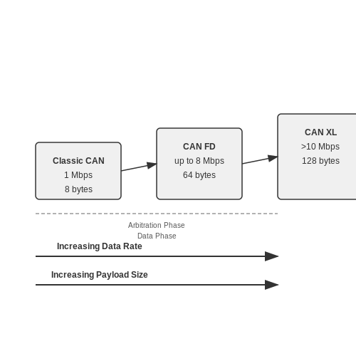
Before diving into CAN FD and CAN XL, understanding the limitations of the classic CAN protocol is essential. The original CAN specification allowed for a maximum data rate of 1 Mbps and a payload size of up to 8 bytes. However, as automotive systems and industrial machinery grew in complexity, the need for faster communication and larger data payloads became apparent.
CAN FD arose to address these requirements, introducing a flexible data rate mechanism. This allows higher data transfer rates of up to 8 Mbps in certain configurations. Furthermore, CAN FD permits a payload size that can extend to 64 bytes per message, significantly improving the data capacity per transmission.
Technical Specifications of CAN FD
To comprehend the enhancements CAC FD offers, it's crucial to look at its technical architecture:
- Flexible Data Rate: CAN FD allows for a faster data rate in the data phase of communication. The transition from the arbitration phase to the data phase enables this change, effectively separating the two phases for optimal performance.
- Increased Payload Size: By extending the payload capability, CAN FD allows larger sets of data to be transferred in a single message, which is ideal for complex systems where multiple sensor data points must be combined.
- Backward Compatibility: CAN FD maintains compatibility with classic CAN, ensuring legacy systems can still operate while leveraging new features.
Mathematical Implications and Dynamics
The flexibility of the bitrate in CAN FD can be described mathematically. Considering the time division of the CAN frame and the respective segments, we can characterize the effective bitrate as follows:
Where:
- R: Effective bitrate (bps)
- D: Data size in bits
- T: Total transmission time in seconds
The ability to adjust the bitrate and payload allows for a dynamic performance adjustment depending on the network conditions, which is a significant leap from the fixed configuration of classic CAN.
Introducing CAN XL
Following the introduction of CAN FD, which marked a substantial step forward, the development of CAN XL represents the next evolution in CAN technology. CAN XL builds upon the capabilities of CAN FD by further increasing the data payload, extending it to 128 bytes per message and potentially supporting data rates exceeding 10 Mbps. This increase in capacity is crucial for future applications that require the transmission of high-density data, such as in advanced driver-assistance systems (ADAS) and automated driving systems.
Key Features of CAN XL
- Larger Payloads: Enhances the maximum message size, thus allowing for more comprehensive data communication, crucial for complex applications.
- Higher Data Rates: Facilitates quicker data exchanges, reducing latency in communication, which is critical in time-sensitive environments such as automotive safety.
- Advanced Error Handling: Integrates sophisticated error-checking mechanisms that increase reliability and robustness in data transmission.
Real-World Applications
The advancements presented by CAN FD and CAN XL make these protocols particularly relevant in the modern automotive landscape, where safety, efficiency, and real-time data communication are paramount. For instance:
- In vehicular networking, the ability to communicate data from multiple advanced sensors simultaneously enhances the functionality of systems like automatic braking and adaptive cruise control.
- In industrial automation, the integration of CAN FD or CAN XL in robotics allows for faster communication between control units and robots, facilitating improved performance in manufacturing processes.
In conclusion, CAN FD and CAN XL represent pivotal advancements in the capabilities of the CAN protocol, addressing the increasing demand for high-speed, high-capacity communication. Their implementation ensures that CAN technology remains relevant in an era of escalating data requirements.
7.2 Emerging Applications in Autonomous Systems
The Controller Area Network (CAN) bus, originally designed for automotive applications to enable communication between microcontrollers without a host computer, is witnessing a resurgence in interest due to its integration into autonomous systems. These systems, characterized by their ability to operate independently of human intervention, demand robust and reliable communication protocols to achieve safety and efficiency. This subsection explores the various emerging applications of CAN bus communication within autonomous systems and examines its pivotal role in advancing technology.
Integration in Autonomous Vehicles
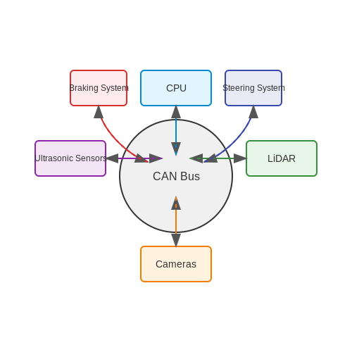
Autonomous vehicles leverage an extensive array of sensors, control units, and computing modules. The CAN bus plays a critical role in ensuring real-time data transfer among these components, which is essential for intricate functions such as navigation, obstacle detection, and route optimization. For instance, communication between the vehicle's braking and steering systems must occur with minimal latency, as safety is paramount in any driving scenario.
- Sensor Fusion: CAN bus facilitates seamless integration of multiple sensor data (LiDAR, cameras, ultrasonic sensors) to provide a holistic view of the vehicle's environment.
- Control Systems: Commands from the central processing unit (CPU) regarding steering and acceleration are rapidly communicated to the respective mechanical systems via the CAN bus.
Application in Robotics
In the realm of robotics, the versatility of CAN bus communication is recognized in applications ranging from industrial automation to service robots. With the push towards Industry 4.0, many manufacturers utilize CAN bus to interlink robotic arms and control systems, enhancing coordination and efficiency on the shop floor.
- Real-time Control: The low-latency nature of CAN facilitates real-time control of robotic movements, essential for tasks requiring precise timing and synchronization.
- Modular Design: A modular approach in robotics enables easy expansion. Adding new components or sensors to the system is merely a matter of connecting them to the CAN bus, reducing downtime and engineering effort.
Impact on Unmanned Aerial Vehicles (UAVs)
Unmanned Aerial Vehicles (UAVs) are also benefitting from the CAN architecture. The communication needs of UAVs often require transmitting commands and telemetry between various subsystems such as propulsion, navigation, and payload management. CAN bus facilitates this intercommunication efficiently.
- Flight Control: Modern UAVs depend on CAN bus for flight control commands and telemetry, adjusting flight paths dynamically based on real-time data.
- Payload Management: Information from the payload (such as cameras or sensors) can be rapidly communicated back to the flight control unit, allowing for immediate adjustments in operation.
Future Directions and Challenges
The implementation of CAN bus in emerging autonomous systems presents promising possibilities. However, challenges remain, particularly concerning data security and bandwidth limitations. Innovations in CAN protocols, such as CAN-FD (Flexible Data-rate), offer solutions by enabling larger data payloads and higher speeds, thereby addressing some of the inherent limitations of traditional CAN systems.
As we move towards a future where autonomous systems proliferate across multiple sectors—transportation, manufacturing, and even agriculture—the importance of robust communication frameworks like the CAN bus cannot be understated. The combination of reliability, efficiency, and versatility positions the CAN bus as a cornerstone for the development of not just smarter vehicles but smarter industries overall.
Future research may focus on enhancing security protocols tailored for CAN communications in autonomous environments, ensuring that as autonomy progresses, so too does the safety and integrity of these systems.
7.3 Overview of Alternative Communication Protocols
The Landscape Beyond CAN Bus
The Controller Area Network (CAN) bus protocol has been a cornerstone of communication in automotive and industrial applications, enabling efficient real-time data transmission. However, as technological advancements increase demand for higher bandwidths, lower latencies, and more complex communication frameworks, alternative protocols have emerged to complement or in some cases, replace CAN. Understanding these alternatives is crucial for engineers and researchers who wish to design robust systems that meet the diverse needs of modern applications.
Beyond CAN: Alternative Protocols
Among the notable alternatives to the CAN bus are protocols like LIN (Local Interconnect Network), FlexRay, Ethernet, and RS-485. Each offers distinct advantages tailored to specific use cases, ranging from in-vehicle networks to industrial control systems.
LIN - The Low-Cost Option
LIN operates at lower speeds (up to 20 Kbps) compared to CAN and is characterized by its simplistic architecture, featuring a master-slave configuration. This protocol is often used in applications such as body control functions (e.g., window control, interior lighting) where cost-effectiveness is paramount.
FlexRay - The High-Speed Connector
FlexRay provides a significant leap in performance, enabling data rates of up to 10 Mbps and deterministic communication. It utilizes a time-triggered approach, making it suitable for applications requiring high reliability, such as advanced driver assistance systems (ADAS). The architecture includes both static and dynamic segments, allowing a blend of timing precision and flexibility.
Ethernet - The Future of Networking
As industries push for higher data throughput, Automotive Ethernet has gained traction, particularly with the advent of connected vehicles. With speeds up to 1 Gbps, Ethernet supports complex data-rich applications like real-time video processing in autonomous systems. Additionally, the Ethernet framework allows an integration of various protocols, creating a versatile platform for future developments.
RS-485 - A Robust Communication Standard
RS-485 stands out for its long-distance communication capabilities and reliability in noisy environments. It supports multi-drop configurations, allowing up to 32 devices on a single bus, making it highly effective for industrial automation tasks. Its simplicity and robustness have led to widespread use in factory settings for monitoring and control.
Comparative Analysis: Protocol Selection Criteria
When selecting a communication protocol, engineers must consider a range of factors:
- Speed: Evaluate the necessary data rate for the intended application.
- Topology: Determine if a master-slave or peer-to-peer configuration is required.
- Cost: Assess budget constraints, which heavily influence protocol choice.
- Scalability: Consider the future scalability of the network in terms of device addition and data throughput.
- Environmental Resilience: Ensure the chosen protocol can withstand the physical and electrical conditions of the application environment.
The implications of these choices can affect system performance, reliability, and maintenance costs, thus warranting a careful analysis based on specific project requirements.
Practical Application Cases
For instance, in the automotive sector, LIN might be selected for managing simpler subsystems, while FlexRay could be the choice when addressing safety-critical functions. Conversely, Ethernet's rising prominence showcases a trend toward higher data throughput needs, reflecting broader technological trends toward connectivity and integration.
Ultimately, while CAN bus remains a stalwart in the communication landscape, the emergence of diverse alternatives allows engineers to tailor solution architectures that best fit their functional and operational requirements. By understanding these protocols, professionals can make informed decisions that significantly enhance system capabilities and efficiency.
This deeper insight into alternative communication protocols emphasizes not just their intrinsic technical specifications but also their contextual relevance, aligning theoretical knowledge with real-world application in an increasingly interconnected environment.
8. Recommended Books
8.1 Recommended Books on CAN Bus Communication
- Controller Area Network Projects: Practical Applications with Embedded Systems — This book offers a thorough examination of practical applications for CAN systems with a focus on embedded systems. With extensive case studies and real-world examples, it provides a hands-on approach to learning about CAN bus communication.
- Controller Area Network (CAN) Basics and Practice — A comprehensive guide for engineers wishing to deepen their understanding of the CAN network. This work covers not only the basics but also advanced features and future trends in CAN technology.
- Automotive Networking: Driving the Future of Embedded Systems — This book delves into the application of CAN in automotive environments, illustrating how networking is driving the future of automotive technology. It provides both theoretical knowledge and practical applications relevant to current industry practices.
- CAN System Engineering: From Theory to Practical Applications — Geared towards researchers and engineers, this book provides a detailed exploration of both the theoretical and practical aspects of CAN systems, with emphasis on design, implementation, and future challenges.
- Controller Area Network: Automotive Electronics Resource Book — This title serves as a resourceful compendium on the use of CAN in automotive applications. It includes contributions from industry experts and covers both foundational concepts and innovative deployments.
- CAN Bus Design and Safety — Focuses on the design and safety considerations of CAN bus systems. The book is ideal for advanced readers interested in understanding the reliability and security aspects critical to the deployment of CAN in safety-critical applications.
- The Automotive IATF: A Comprehensive Introduction to CAN — A resource tailored for those in the automotive industry looking to better understand the role of CAN technologies and standards. It provides a comprehensive introduction to the CAN protocol within the context of automotive functional safety.
8.2 Academic Journals
For those looking to deepen their understanding of CAN Bus Communication, numerous academic journals provide rigorous, research-backed insights into its complexities and applications. Here is a curated list of high-quality academic resources to explore:
- IEEE Xplore Digital Library — Explore an array of scholarly articles on electronic systems, including cutting-edge research papers on CAN Bus technology.
- SAGE Journals - International Journal of Electrical Engineering & Education — This journal hosts numerous peer-reviewed papers and case studies focusing on advanced communication protocols like CAN Bus.
- Automatica Journal — Access papers on systems and control, featuring studies on CAN Bus applications in automotive and industrial settings.
- ACM Transactions on Embedded Computing Systems — Dive into articles addressing the complexities of embedded systems, including developments in CAN Bus technologies.
- Control Engineering Practice Journal — Find applied research articles related to control engineering, with relevant insights into CAN Bus system implementations.
- Mechatronics Journal — Offers research articles examining the integration of mechanical, electrical systems with CAN Bus applications spotlighted in mechatronic designs.
- International Journal of Robotics Research — This journal includes studies on robotic systems that utilize CAN Bus frameworks, providing both theoretical and practical perspectives.
- Springer - Journal of Control, Automation and Electrical Systems — Provides valuable insights into the electrical systems and automation technologies, featuring advancements in CAN Bus systems.
8.3 Online Resources
- CAN in Automation (CiA) — This organization is the international users' and manufacturers' group supporting the CAN protocol. It provides resources, technical specifications, and guidelines for implementation.
- Vector CAN Protocol Tutorial — A comprehensive introduction to CAN Bus Protocol. Vector provides extensive technical papers, including use cases and implementation guidance.
- NXP CAN Protocol Summary — This application note from NXP provides a detailed overview of the CAN protocol, including its history, message formatting, and error handling.
- Kvaser CAN Protocol Tutorial — Kvaser offers an in-depth tutorial on the core elements of CAN Bus, covering its structure, advantages, and practical implementation tips.
- Microchip's CAN Tips and Tricks — Provides practical insights and tips for designing robust CAN applications, focusing on hardware considerations and network design.
- Vector CAN e-Learning — Offers a variety of online learning modules on CAN, including video tutorials and interactive courses tailored for engineers and professionals.
- Texas Instruments: Understanding CAN Protocol — A technical document from Texas Instruments explaining the CAN protocol's operational details, fitting for advanced users seeking in-depth technical understanding.