Breadboarding

#breadboard #jumper wires #prototyping #circuit setup #terminal strips #power rails #troubleshooting #components connection #electronics prototyping #basic circuits
1. What is a Breadboard?

1.1 What is a Breadboard?

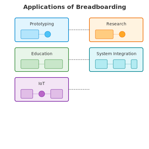
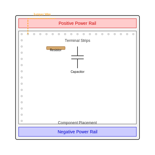
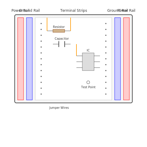
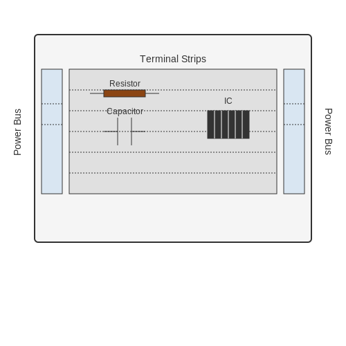
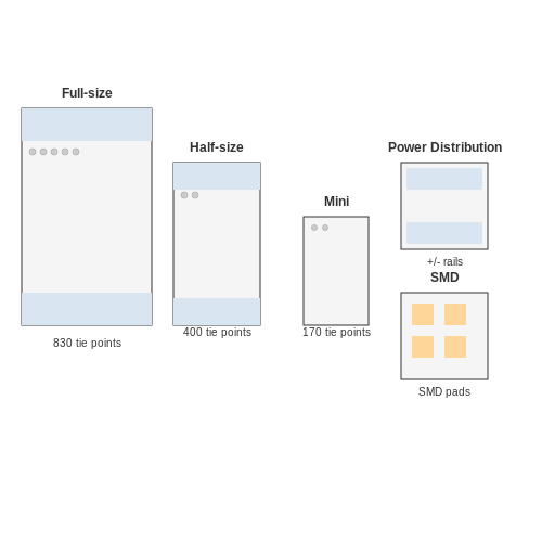
Breadboarding is an essential technique used in the rapid prototyping and testing of electronic circuits. At its core, a breadboard is a reusable platform that allows engineers and designers to construct electronic circuits without the need for soldering. This versatility makes it an invaluable tool in both educational and professional settings. The basic structure of a breadboard consists of a grid of holes arranged in rows and columns, typically with conductive metal strips underneath the plastic surface. These strips are wired in such a way that they connect various holes vertically or horizontally, providing a convenient way to insert component leads into the board and create connections. The ease of connection allows engineers to quickly assemble a circuit, test functionality, and make adjustments in real-time. One of the most common configurations includes the power rails, which run along the top and bottom of the board, designated for positive and negative voltage connections. These rails simplify the process of distributing power to multiple components without the need for individual connections to a power source. Additionally, the central area of the board is where the actual components, such as resistors, capacitors, and integrated circuits (ICs), are inserted. Historically, breadboards were literal boards made of wood or a solid material that allowed for components to be mounted and soldered. The evolution to the modern, plastic breadboard has facilitated a significant decrease in timeframe and complexity, transforming how engineers prototype circuits. Real-World Applications The applications of breadboarding extend across various fields, including audio electronics, microcontroller interfacing, and signal processing. In academic settings, students often use breadboards to solidify their theoretical understanding of circuit design. For professionals, breadboards are critical in the research and development phase, where valid concepts can be explored and validated through empirical testing. Breadboarding also plays a vital role in embedded systems development, where programmers and engineers work with microcontrollers and sensors. The ability to quickly iterate designs without the need for soldering allows teams to reduce time-to-market for their products. As we delve deeper into breadboarding techniques, it is essential to explore how to effectively select and organize components on the breadboard, optimize circuit designs, and troubleshoot common issues encountered during prototyping. Understanding these aspects will empower engineers to leverage breadboarding as a flexible tool in their electronic design toolkit. To facilitate this discussion, we will explore specific strategies for component arrangement and circuit design in the subsequent sections.
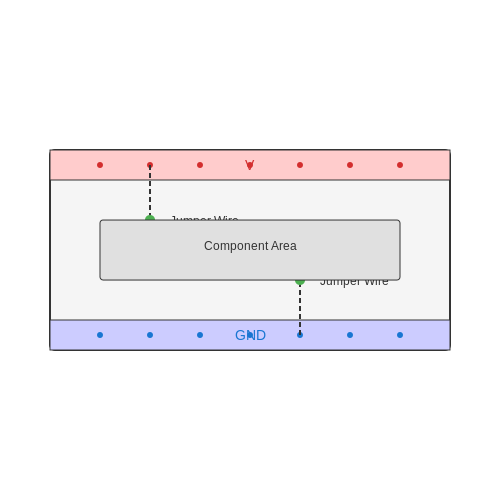
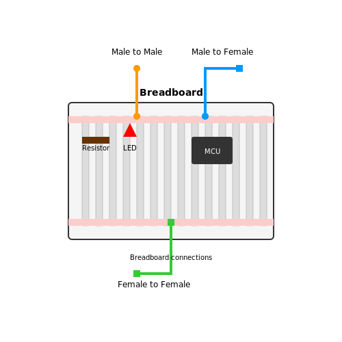
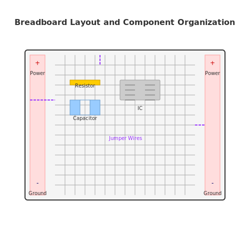
Breadboard Layout Diagram Top-down view of a typical breadboard with labeled power rails, rows, and columns, showing components like resistors and capacitors inserted. + Power Rail - Power Rail Diagram Description: The diagram would illustrate the layout of a breadboard, showing the arrangement of holes, power rails, and how components are connected. This visual representation would clarify the spatial relationships and functionalities that text alone may not convey effectively.