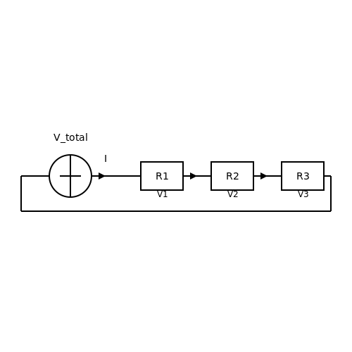
Applied Breadboarding
1. What is Breadboarding?
1.1 What is Breadboarding?
Breadboarding is a fundamental practice in electronics that allows for the rapid prototyping of electronic circuits without the need for soldering. This technique utilizes a breadboard, a reusable device featuring a grid of interconnected points to facilitate the assembly of electronic components. The benefits of breadboarding extend beyond mere convenience; it represents an essential pedagogical tool for engineers, physicists, and researchers, providing a dynamic platform for experimentation and innovation.
The history of breadboarding can be traced back to the early days of electronics, where wooden boards were literally used to hold circuits together. Modern breadboards have evolved significantly, often composed of plastic and featuring metal "americana" clips that enhance connectivity and ease of use. Historically, this innovation enabled designers to test and iterate their ideas rapidly, reflecting the iterative nature of electronic design that we see today.
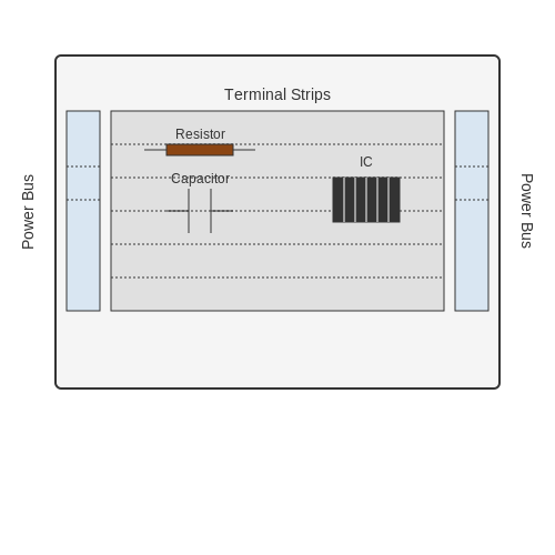
At its core, a breadboard consists of two main sections: the terminal strips and the power bus. The terminal strips are arranged in rows and columns, with horizontal and vertical connections that allow components such as resistors, capacitors, and integrated circuits to be easily placed and rearranged. The power bus typically runs along the top and bottom of the board, providing a convenient means to connect power to different parts of the circuit.
When designing with a breadboard, it is essential to consider factors such as component placement and wiring to ensure that the circuit functions correctly. For instance, power supply connections must be clearly marked, and components must be oriented correctly to prevent short circuits or incorrect operation. The breadboard encourages a visual representation of the circuit that aids not only in debugging but also in understanding the flow of signals and power within the design.
The real-world applications of breadboarding span various domains. In academic settings, it serves as an effective teaching tool, allowing students to grasp complex concepts such as Ohm's law, Kirchhoff's laws, and the behavior of operational amplifiers through hands-on experimentation. In the industry, engineers use breadboards for initial testing phases of product development before transitioning to more permanent solutions, such as printed circuit boards (PCBs).
Furthermore, breadboarding supports the transition from concept to prototype, offering a platform to verify design specifications and integrate various functionalities. For example, a designer might test a microcontroller's I/O capabilities on a breadboard before finalizing the layout on a PCB. Such iterative testing provides invaluable data, ensuring that the final product meets performance expectations and regulatory standards.
As the landscape of electronics continues to evolve, particularly with the rise of embedded systems and the Internet of Things (IoT), the role of breadboarding remains crucial. The ability to experiment with and prototype devices quickly allows for greater innovation and adaptability in a fast-paced technological environment.
Conclusion
In conclusion, breadboarding represents more than just a method of assembling electronic components; it encapsulates the spirit of experimentation fundamental to engineering and physics. By providing a flexible and accessible means to create and test circuits, breadboards empower engineers, researchers, and students alike to explore, innovate, and refine their ideas efficiently.
1.2 Common Components and Tools
In the realm of applied breadboarding, familiarity with common components and tools is essential for engineers, physicists, and advanced practitioners. Understanding these elements facilitates effective prototyping and iterative design, enabling the realization of complex electronic systems. Let us delve into the essential components and tools that form the backbone of any breadboarding experience.
Passive Components
Passive components are fundamental elements in circuit design that do not require an external power source to operate. Their functionality lies in modifying voltage and current within a circuit. The most commonly used passive components include:
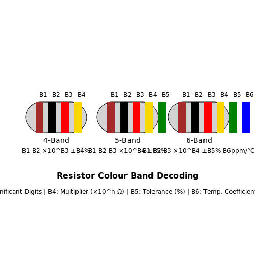
- Resistors: These components limit the flow of electric current and are characterized by their resistance value measured in ohms (Ω). The behavior of resistors is described by Ohm’s Law, which can be expressed as follows:
- Capacitors: Capacitors store and release electrical energy in a circuit, characterized by their capacitance value measured in farads (F). They are vital for filtering, timing, and smoothing voltage fluctuations. The voltage-current relationship for a capacitor is described as:
- Inductors: Similar to capacitors, inductors store energy but in a magnetic field. Their inductance is measured in henries (H), and they resist changes in electric current. The relationship can be similarly described by:
where V is the voltage across the resistor, I is the current flowing through it, and R is the resistance.
This formula illustrates how the current I through a capacitor is proportional to the rate of change of voltage, V.
where L is the inductance and I is the current flowing through the inductor.
Active Components
Active components require an external power source to function and are crucial for amplification and signal processing. Common active components include:
- Transistors: These semiconductor devices are used for switching and amplification. They can be classified as bipolar junction transistors (BJTs) and field-effect transistors (FETs). The current-voltage relationship in a BJT can be approximated by the following equation for the collector current IC:
- Operational Amplifiers (Op-Amps): Op-amps are high-gain voltage amplifiers with differential inputs. They are widely used in various configurations such as amplifiers, filters, and oscillators. The output voltage Vout for a simple non-inverting amplifier configuration can be expressed as:
where IB is the base current and β is the current gain.
where Rf is the feedback resistance and Ri is the input resistance.
Basic Tools for Breadboarding
In addition to components, the right tools are crucial for effective breadboarding. These tools assist in constructing prototypes and experimenting with circuit designs:
- Breadboards: These prototyping boards provide a grid of holes into which components can be inserted without soldering. Their layout allows for easy modification and testing of circuits.
- Power Supplies: A reliable power supply is essential for providing the necessary voltage and current for experiments. Adjustable power supplies are particularly useful for testing various circuit conditions.
- Multimeters: Multimeters measure voltage, current, and resistance, providing critical information about circuit performance. Advanced multimeters can also test various component functionalities, aiding in troubleshooting.
- Wire Strippers and Cutters: Efficient wiring is vital. A good set of wire strippers and cutters simplifies the preparation of wires for connections on the breadboard.
- Oscilloscopes: For analyzing signal waveforms, oscilloscopes provide a visual representation of voltage changes over time, useful for debug and performance evaluation.
Assembling a successful breadboard prototype hinges not only on the components used but also on the mastery of these essential tools. Real-world applications range from basic educational projects to complex system designs, making proficiency in these areas indispensable. Ultimately, continuous experimentation and learning through breadboarding can lead to the development of innovative electronic solutions in a multitude of fields.
1.3 Understanding Breadboard Layout
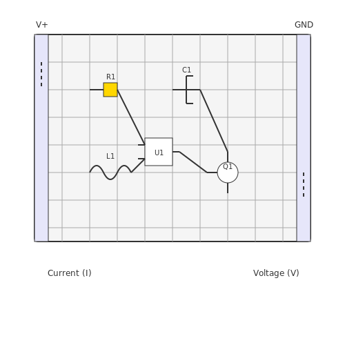
The breadboard is an essential tool for prototyping electronic circuits, allowing for quick adjustments and experimentation without soldering. Its layout supports the easy connection of components such as resistors, capacitors, and integrated circuits (ICs), lending itself to various educational and professional applications in electronics design and testing.
Basic Layout Configuration
The conventional breadboard is organized into a grid of interconnected terminal strips. Understanding this structure is critical for establishing reliable connections. Typically, a breadboard features:
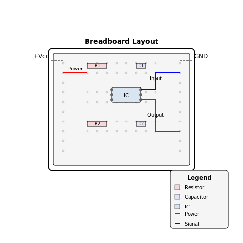
- Power Rails: Located along the top and bottom sides, these horizontal rows provide dedicated paths for positive and negative voltage connections. They are often marked with red and blue lines, respectively, to indicate polarity.
- Terminal Strips: Vertical strips situated centrally within the breadboard. Each strip is subdivided into smaller sections, with each column typically connected electrically in groups of five. This arrangement supports multiple connections in a compact space.
For illustrative purposes, consider a typical breadboard layout. Each segment within the terminal strips is interconnected, forming a conceptual grid that highlights how components can be placed within specific columns for efficiency.
Connection Points and Their Importance
Every connection made on the breadboard becomes crucial when considering signal integrity and circuit performance. The organization of terminal strips ensures that components designed to work closely together can be placed adjacent to each other, reducing potential connection problems.
As a practical exercise, it is advisable to familiarize oneself with the layout by constructing simple circuits. Start with basic components like LEDs and resistors, which facilitate the understanding of current flow and voltage distribution while utilizing limited space effectively.
Common Challenges and Best Practices
While working on breadboards, several challenges often arise. A frequent issue is unintentional short circuits, which occur when components or wires inadvertently touch adjacent strips. To mitigate this risk, follow these best practices:
- Organized Wiring: Use different colored wires for ground, signal, and power connections. This practice enhances clarity and ease of troubleshooting.
- Component Placement: Arrange components logically, ideally starting from the power source and moving outward to minimize wire crossings.
Furthermore, ensure to use a multi-meter to verify connections while debugging circuits, as this can quickly identify erroneous links or open connections without the guesswork.
Conclusion
A thorough understanding of the breadboard layout empowers engineers and researchers to design effective and reliable circuits more adeptly. Mastery of the breadboarding process can lead to enhanced experimental outcomes and innovations in the field of electronics.
2. Simple LED Circuit
2.1 Simple LED Circuit
Understanding the fundamentals of circuit assembly is crucial for anyone delving into applied electronics. One of the simplest yet most illuminating projects is a basic LED circuit. This not only serves as a practical introduction to the principles of circuit design, but it also paves the way for more complex designs involving various electronic components.
Overview of the LED Circuit
An LED (Light Emitting Diode) is a semiconductor device that emits light when an electric current flows through it. For engineers and researchers, grasping the behavior of LEDs in different circuit configurations is essential for applications ranging from simple indicators to sophisticated lighting systems. The circuitry involved tends to be straightforward yet provides a wealth of information about current, voltage, and the combination of these elements.
Circuit Components
The basic components required to set up a simple LED circuit include:
- LED: The light-emitting diode, which will produce light when current flows through it.
- Resistor: A passive component that limits the current flowing through the LED to prevent burnout.
- Power Supply: A voltage source (such as a battery or DC power supply) to provide the necessary forward voltage for the LED.
- Connecting Wires: Conductive pathways that connect the components on the breadboard.
Circuit Schematic
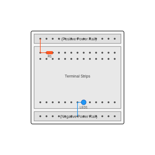
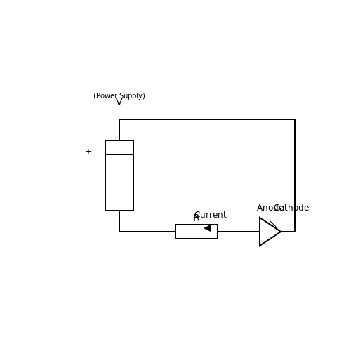
Visualizing the arrangement of the components in a circuit is critical for understanding its operation. In our simple LED circuit, the LED is connected in series with a resistor and a power source. The anode of the LED connects to the positive terminal of the power supply, while the cathode connects to one end of the resistor. The other end of the resistor connects back to the negative terminal. This configuration ensures that the current flows effectively through the LED.
Calculating the Resistor Value
To prevent damage to the LED, it's vital to compute the appropriate resistor value. This can be achieved using Ohm's Law, which states:
Where:
- V: Voltage across the resistor (Vr)
- I: Current flowing through the LED (typically 20 mA for standard LEDs)
- R: Resistance (in ohms)
Assuming a standard LED with a forward voltage of 2V and powered by a 9V battery, the voltage drop across the resistor will be:
Next, applying Ohm's Law allows us to solve for R:
Thus, a resistor of approximately 350 ohms is required to safely limit the current through the LED. Standard values can be chosen (such as 360 ohms) to fit within the tolerances of readily available resistors.
Practical Applications
Once the basic LED circuit has been mastered, enthusiasts can delve deeper into its practical applications. Examples include:
- Indicators: Utilized in consumer electronic interfaces to signal power status or faults.
- Illuminated Displays: A fundamental component in numerals and symbols in electronic displays.
- Light Sensors: Incorporated in photonic devices that adjust light based on ambient conditions.
This simple LED circuit thus serves as a foundational step into more complex electronics, where principles of voltage, current, and resistance recur across various applications. Mastery in creating this circuit opens doors to innovation in electronic design and applications.
2.2 Resistor and LED Series Circuit
In the realm of applied breadboarding, the series circuit configuration of resistors and light-emitting diodes (LEDs) represents a fundamental yet potent concept that intertwines theory with practical application. This subsector delves into the crucial principles governing this configuration, providing a deep understanding that is vital for any advanced-level engineer, physicist, or researcher. With a grasp of these principles, readers can innovate upon classic designs and find application in everything from basic signaling to complex illumination systems.
Understanding the Series Circuit Concept
A series circuit entails connecting devices end-to-end, resulting in a single pathway for current flow. As such, the same current traverses through each component, leading to shared voltage among the circuit elements. This configuration is particularly relevant when utilizing resistors in conjunction with LEDs, as it governs both the functionality and longevity of the components involved.
Key Considerations:
- Current Consistency: The current remains constant across all components.
- Voltage Distribution: The total voltage provided by the power source is divided among the components based on their resistances.
Designing the Resistor and LED Series Circuit
The fundamental requirement for operating an LED safely is to control the current flowing through it. LEDs typically have a specified forward voltage drop, depending on their color and type, which must be accounted for in the design. Adding a resistor in series helps to limit the current, preventing the LED from exceeding its maximum rated current.
This section proceeds to derive the relationship governing the design of a series resistor-LED circuit. Consider a simple circuit with a voltage source, an LED, and a resistor as shown below:
Here, \( V_s \) is the source voltage, \( V_{LED} \) is the forward voltage drop across the LED, and \( V_R \) is the voltage across the resistor. The relationship can also be expressed in terms of current, \( I \), flowing through the circuit:
By Ohm's Law, we have:
Substituting back into the first equation gives:
Now, solving for the resistor value \( R \):
Through this equation, one can determine the resistance necessary to ensure the LED operates within safe parameters. It is essential to select an appropriate resistor based on the available supply voltage, the LED's forward voltage, and the desired current.
Practical Applications
The versatility of the resistor and LED series circuit extends beyond mere illumination. They serve as critical components in:
- Indicator Lights: Used to convey system statuses in various electronic devices such as appliances and computers.
- Visual Alerts: Employed in alarms or notifications systems that require visual indication.
- Decorative Lighting: Widely utilized in decorative setups and artistic displays.
Illustratively, consider a prototype where a series-circuit arrangement of resistors and LEDs is used in a simple signaling system. Controlling multiple LEDs using varying resistors can provide different brightness levels, thus enabling a clear visual feedback mechanism.
Conclusion
In conclusion, mastery of the series circuit configuration involving resistors and LEDs is indispensable for advanced-level practitioners. It lays the groundwork for designing intricate electronic devices while fostering a comprehensive understanding of current, voltage, and resistance interactions. Furthermore, this knowledge feeds into higher-level concepts, facilitating progress through both theory and practical implementation, ultimately driving innovation in electrical engineering.

2.3 Parallel Circuit Configuration
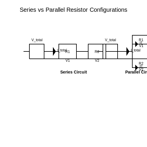
In electronic circuits, parallel configurations are fundamental in the design for various applications ranging from power distribution to signal processing. Understanding how components behave in a parallel arrangement is crucial for any engineer or physicist, especially when precise control over voltage and current is required. In a parallel circuit, each component is connected across the same two points, meaning that all components experience the same voltage. However, the current through each component may vary, allowing for an intricate balancing of load, which is essential in many practical applications.
Fundamentals of Parallel Circuits
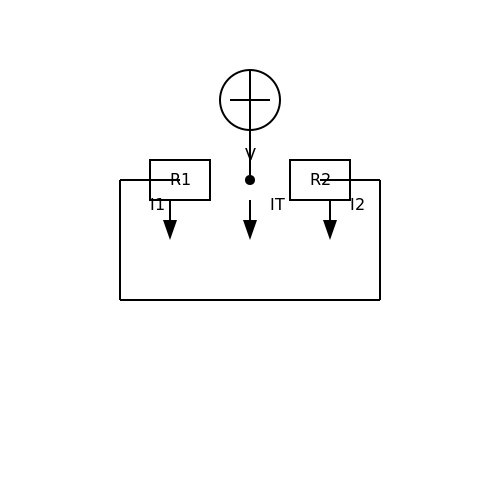
To describe a parallel circuit mathematically, let’s consider a simple scenario where we have two resistors, \( R_1 \) and \( R_2 \), connected in parallel across a voltage source, \( V \). The voltage \( V \) across both resistors is the same. According to Ohm's Law, the current through each resistor can be expressed as:
The total current \( I_T \) entering the junction where the resistors meet can be found by summing the individual currents:
Factoring out \( V \), we can derive an expression for total current:
From this, we can see that the equivalent resistance \( R_{eq} \) for resistors in parallel can be derived as:
This equation illustrates a key characteristic of parallel configurations: the equivalent resistance is always less than the smallest resistor in the network, allowing for greater total current to flow through the circuit.
Real-World Applications
Parallel circuits are extensively used in electrical wiring systems, such as residential homes and commercial buildings. For instance, multiple appliances can be connected in parallel to ensure that each device receives the full line voltage regardless of the other devices' states. This configuration is essential for ensuring reliability and functionality in practical scenarios.
Another notable application is found in power supply systems. In power distribution networks, transmission lines often run in parallel to minimize losses and optimize power delivery over large distances. Each line can be controlled and adjusted individually to manage load requirements effectively.
Design Considerations
While parallel circuits offer numerous advantages, they also require careful design considerations. For example, if one component fails (open circuit), the remaining components continue to operate, which is beneficial. However, if a parallel component creates a short circuit, it can lead to excessive current flow, potentially damaging the system. Thus, implementing proper fuses and circuit breakers is essential in circuit design to mitigate such risks.
When breadboarding a parallel circuit, it is crucial to ensure good connections and to verify the characteristics of each component before deployment. Using simulation tools can help predict circuit behavior, providing a valuable platform for experimenting with various configurations.
Through an understanding of parallel circuit configurations, engineers and researchers can harness the power of these arrangements in diverse applications, enhancing both efficiency and performance in electronic designs.
3. Modular Circuit Design
3.1 Modular Circuit Design
The concept of modular circuit design is pivotal for enhancing the usability and flexibility of electronic development. By partitioning complex systems into manageable modules, engineers can design, test, and iterate individual components without compromising the integrity of larger systems. This approach not only improves efficiency in prototyping but also facilitates clearer organization and troubleshooting.
The Principle of Modular Design
Modular design is grounded in the principle of separation of concerns, which dictates that a system—or in this case, a circuit—should be divided into distinct components, each responsible for specific functions. This isolation allows for easier debugging, as failures in one module can be diagnosed without excessive interaction with other modules.
Historically, modular design has roots in software engineering, where it emerged from the need for code reusability and maintainability. In electronics, similar concepts have led to the development of standardized components, such as Integrated Circuits (ICs) and expansion boards, that can be effortlessly integrated into various projects.
Benefits of Modular Circuit Design
- Increased Flexibility: Modules can be added, removed, or replaced as required, facilitating rapid prototyping and design iterations.
- Improved Collaboration: Teams can work on different modules simultaneously, streamlining the design process and improving project timelines.
- Enhanced Troubleshooting: Isolating components simplifies the debugging process, as issues can be traced back to specific modules rather than an entire circuit.
- Reusability: Well-designed modules can be reused across different projects, saving time and resources in future designs.
Designing Modules
When designing a modular circuit, consider the interface between modules, focusing on both electrical and physical connections. For example, a well-defined pinout specification can prevent misconfigurations while ensuring compatibility across varying modules. Additionally, standardizing power requirements—such as voltage levels and currents—across modules can greatly simplify power management within a design.
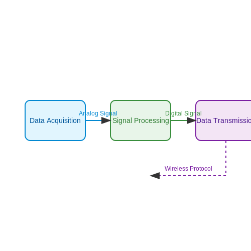
Let's consider a practical example: developing a sensor readout system where separate modules handle data acquisition, signal processing, and data transmission. Each module performs its operation independently and communicates through a well-defined interface, ensuring clear data flow and system functionality.
Case Study: Sensor Readout System
In a case study involving a temperature sensor, the data acquisition module consists of an analog-to-digital converter (ADC) that converts the analog output of the sensor into a digital format. The signal processing module uses a microcontroller to filter and analyze the data, while the transmission module communicates the processed data to a monitoring system using a wireless protocol. This clear separation not only enhances reliability but also allows teams to work on each module concurrently.
Challenges in Modular Circuit Design
While modular circuit design offers substantial advantages, it also presents challenges. The interaction between modules needs careful attention to mitigate issues such as compatibility, signal integrity, and noise isolation. Additionally, the increased number of interfaces can complicate troubleshooting if not properly documented.
In conclusion, the modular approach in circuit design provides remarkable benefits, including flexibility, improved collaboration, and better use of resources. As electronic systems become increasingly complex, the need for effective modular design strategies will only grow. Embracing this methodology, while being aware of the associated challenges, will empower engineers to build sustainable and scalable electronic systems.
3.2 Using Integrated Circuits
In modern electronic design, integrated circuits (ICs) have significantly revolutionized the complexity and efficiency of circuit architectures. Unlike discrete components, ICs integrate numerous active and passive components into a single chip, enabling compact circuit designs with enhanced performance. Their prevalence in applications ranging from consumer electronics to sophisticated industrial systems underscores their crucial role in contemporary engineering.
Understanding Integrated Circuits
At the core of integrated circuits lie processes that combine different functionalities, such as amplification, logic processing, and memory storage, onto a singular substrate. The historical context of ICs dates back to the 1950s, marking the transition from vacuum tubes and discrete components to solid-state technology. This shift not only improved reliability and efficiency but also paved the way for the rapid miniaturization of electronic devices.
Types of Integrated Circuits
ICs can be categorized into two main types: analog and digital. Analog ICs, such as operational amplifiers (op-amps) and voltage regulators, operate on continuous signals, making them essential in amplification, filtering, and signal conditioning tasks. Conversely, digital ICs, which encompass logic gates, microcontrollers, and memory chips, handle discrete signals and are foundational to computational tasks.
Operational Amplifiers: A Prime Example
Operational amplifiers exemplify the utility of analog ICs. Typically represented as a three-terminal device with inverting, non-inverting, and output terminals, op-amps boast an exceedingly high open-loop gain, making them ideal for applications that require precise signal amplification. The following equation governs their behavior in a typical non-inverting amplifier configuration:
Here, \( V_{out} \) is the amplifier's output voltage, \( V_{in} \) is the input voltage, \( R_f \) is the feedback resistor, and \( R_i \) is the input resistor. This relationship highlights the linear nature of op-amps under specific conditions, leading to widespread applicability in signal processing applications.
Practical Considerations for Breadboarding with ICs
When working with ICs on a breadboard, certain best practices enhance the reliability and functionality of designs:
- Power Supply Considerations: Always ensure that the voltage levels match the specifications of the IC. For example, a common op-amp like the LM358 operates typically at voltages from 3V to 32V, and exceeding these can damage the component.
- Pin Configuration: Familiarize yourself with the pin layout delineated in the IC's datasheet. Taking advantage of resources like pinout diagrams is essential for avoiding misplacements that can lead to circuit failure.
- Decoupling Capacitors: It is advisable to place decoupling capacitors (commonly 0.1 µF) near the power pins of digital ICs. This mitigates the effects of noise and ensures stable operation.
- The Use of Breadboards: Leverage the flexibility of breadboards for prototyping. However, keep in mind that breadboards introduce parasitic capacitance, potentially affecting high-frequency applications.
Conclusion
In summary, the incorporation of integrated circuits into breadboarding practices significantly enhances circuit design efficiency and effectiveness. Whether utilizing them for analog tasks such as amplification or digital functions like computation, understanding their functionalities and practical considerations can lead to innovative and robust electronic solutions. By mastering these components, engineers can push the boundaries of electronics, paving the way for future advancements in technology.

3.3 Signal Processing Circuits
Signal processing circuits encompass a vast domain of techniques and methodologies aimed at manipulating and analyzing signals to extract meaningful information. In the context of applied breadboarding, mastering signal processing circuits is invaluable for engineers and researchers as they transition from theoretical concepts to tangible implementations. This section delves into fundamental components and design techniques used in signal processing, enhancing both functionality and performance in practical scenarios.
Understanding Signal Types
At the core of signal processing lies the distinction between different signal types: analog and digital signals. Analog signals are continuous in nature and can take on any value within a given range, representing real-world phenomena such as sound, temperature, and light. Conversely, digital signals are discrete, represented by binary values (0s and 1s), which are crucial for computer-based systems and digital communication.
Every signal can be characterized by its frequency components, amplitude, and phase. Using Fourier analysis, we can transform a time-domain signal into its frequency-domain representation, which is foundational for various signal processing applications. Analyzing signals in the frequency domain provides insights that are often obscured in the time domain, leading to more efficient system designs.
Essential Components of Signal Processing Circuits
When constructing signal processing circuits on a breadboard, several components play pivotal roles:
- Filters: These circuits selectively amplify or attenuate certain frequency components of signals. Common types include low-pass, high-pass, band-pass, and notch filters. For instance, a low-pass filter allows frequencies below a certain cutoff while attenuating higher frequencies.
- Amplifiers: Used to increase the amplitude of signals. Operational amplifiers (op-amps) are widely utilized due to their versatility and high gain characteristics.
- Analog-to-Digital Converters (ADCs): These devices convert analog signals to their digital counterparts, essential for digital signal processing. Understanding their resolution and sampling rates is vital for accurate signal representation.
- Microcontrollers: These are integral for implementing digital signal processing algorithms. They can perform operations on the digital signals obtained from ADCs, allowing for complex processing tasks.
Designing Filters
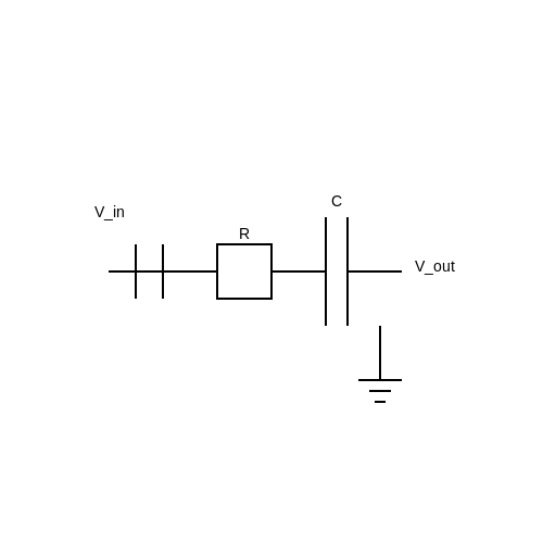
To illustrate the design of a low-pass filter, consider the following passive RC low-pass filter configuration:
The circuit consists of a resistor (R) and a capacitor (C) arranged in series. The output voltage is taken across the capacitor, and the input voltage is applied to the series combination of R and C.
The cutoff frequency \( f_c \) of the low-pass filter can be derived from the formula:
Where:
- R is the resistance in ohms (Ω),
- C is the capacitance in farads (F).
The frequency response of the filter shows that frequencies below \( f_c \) pass with minimal attenuation, while frequencies above \( f_c \) are increasingly attenuated. In practice, tweaking R and C values enables designers to customize the filter's characteristics for specific applications.
Implementing Circuits on a Breadboard
Building a signal processing circuit on a breadboard provides an excellent hands-on learning opportunity. For instance, one might set up a low-pass filter using an op-amp configuration along with resistors and capacitors. By changing component values and observing the output using an oscilloscope, one can grasp how the circuit alters the signal characteristics in real-time.
This tangible interaction with electronic components reinforces theoretical knowledge and enhances problem-solving skills. Experimenting with different configurations, one can explore applications ranging from audio processing to sensor signal conditioning.
Real-World Applications
The principles of signal processing have extensive applications across various fields:
- Audio processing: Enhancements in music systems, noise cancellation technology, and real-time audio effects.
- Telecommunications: Signal conditioning for better transmission of voice and data in communication systems.
- Image Processing: Filters are used to enhance image quality by removing noise and improving features.
- Biomedical Engineering: Signal processing techniques employed to analyze bio-signals such as ECG and EEG for medical diagnostics.
In summary, mastering signal processing circuits on a breadboard goes beyond basic electronics. It bridges theoretical knowledge with practical skills, equipping engineers and researchers to innovatively design and implement advanced signal handling systems.
4. Common Issues and Solutions
4.1 Common Issues and Solutions
When engaging in applied breadboarding, a prototyping technique paramount to electronic circuit design, engineers and researchers often encounter a range of issues. These challenges can arise from both the inherent nature of the prototyping process and the specific design choices made during development. Addressing these common issues requires a blend of foundational knowledge, practical reasoning, and sometimes, innovative problem-solving.
Intermittent Connections
One prevalent issue in breadboarding is intermittent connections, often caused by poor contact between components and the breadboard's sockets. Frequently, this results from:
- Misalignment of component leads within the breadboard.
- Contaminated or oxidized contacts, which can impede electrical flow.
- Wear and tear on the breadboard itself, leading to loose connections.
To mitigate these issues, it is advisable to regularly inspect all connections and ensure that component leads fit snugly into the breadboard. Additionally, using a contact cleaner can remove oxidation, and taking care to avoid mechanical stress on the components will prolong contact reliability.
Noise and Signal Integrity Issues
Signal integrity is often compromised in breadboard setups due to parasitic capacitance and inductance, which can introduce noise. Such issues are especially pronounced in high-frequency applications. The layout of the components plays a crucial role in managing these effects:
- Avoid long wiring runs, as they can act as antennas, picking up external noise.
- Minimize the use of jumper wires; where possible, opt for direct connections.
- Group related components closely to reduce the distance signals must travel.
To further examine this, consider the following snippet of analysis of coupled parasitic capacitance between two adjacent wiring paths:
Here, \(C_{total}\) represents the total parasitic capacitance that can drastically affect circuit performance, indicating that reducing distances and optimizing layout plays a significant role.
Power Supply Issues
Inadequate or fluctuating power supplies can lead to unstable circuit behavior. This can be caused by:
- The use of power supplies that do not provide adequate current for the circuit's demands.
- Noise generated in the power supply, introducing unwanted voltage variations.
To ensure stable performance, assess the power supply specifications against the circuit requirements. employing decoupling capacitors near the power pins of integrated circuits (ICs) can also help buffer voltage fluctuations.
Overheating Components
Overheating is another significant concern, often leading to component failure. This can occur for several reasons:
- Components are operated beyond their rated current or voltage specifications.
- Inadequate thermal management solutions, particularly in high-power applications.
To avoid overheating, familiarize yourself with component tolerances, ensuring that any experimental conditions remain within those limits. Consider implementing heatsinks or thermal pads for high-power components to improve thermal dissipation.
Debugging Techniques
Finally, debugging on a breadboard can prove difficult due to the complexity of interconnected components. A systematic approach is vital:
- Use an oscilloscope to visualize signal integrity across various nodes.
- Employ a multimeter to check voltages, ensuring power levels match expected values.
- Iteratively isolate sections of the circuit for detailed analysis.
These steps will help pinpoint issues more effectively, facilitating a cycle of rapid iteration and improvement.
By adopting these practices and preparing for common challenges, practitioners can enhance the efficacy of their breadboarding sessions, ultimately leading to successful prototyping and development of electronic circuits.
4.2 Testing Circuit Functionality
Testing circuit functionality is a vital step in verifying the design and performance of any electronic system. This process not only ensures that the circuit operates as intended under expected conditions but also aids in identifying potential issues before deployment. When engaging in circuit testing, an understanding of both theory and practicality is essential. For engineers and researchers, this phase often involves various methodologies including both analog and digital techniques, each chosen to match the specific characteristics of the circuit in question.Understanding the Basics of Circuit Testing
Before delving into testing methods, it's crucial to establish the parameters that define *correct functionality*. These typically include voltage levels, current magnitudes, signal integrity, and response times. The choice of measurement equipment, like oscilloscopes for time-domain analysis or multimeters for voltage and current measurement, plays a fundamental role in effectively assessing these parameters. Accurate testing also requires a reference point—a flawlessly designed circuit or a simulation model that represents the expected behavior. By comparing the measured output against this ideal standard, discrepancies can highlight malfunctioning components, wiring errors, or incorrect configurations.Testing Techniques and Methodologies
A broad spectrum of testing techniques exists, including:- Functional Testing: This approach verifies that the circuit performs its designed functions. For example, if testing an amplifier, one would assess the gain, bandwidth, and distortion levels.
- Parametric Testing: This focuses on measuring specified parameters under various conditions. One might apply a range of frequencies to a filter and observe the cutoff behaviors.
- Stress Testing: Evaluating the circuit’s performance during extreme conditions (e.g., high temperatures, over-voltage) aids in assessing reliability and robustness.
- Boundary Testing: This technique investigates circuit behavior at its operational limits, ensuring stability and functionality at threshold values.
Implementing Testing Solutions
To implement effective testing, one must follow a structured plan: 1. Preparation: Gather necessary tools such as probes, function generators, and oscilloscopes. 2. Setup: Ensure all equipment is calibrated and ready. Connect probes to the correct nodes as indicated in the circuit schematic. 3. Testing Procedure: Execute tests sequentially, recording measurements meticulously. For example, applying a known input and measuring the corresponding output helps validate transfer characteristics. 4. Analysis and Comparison: Analyze the recorded data against expected values to identify any deviations. 5. Iterative Testing: Revisit tests after modifications to verify that adjustments enhance functionality rather than detract from it. A practical application of these techniques can be observed in designing signal processing circuits. Engineers often perform series of tests on filters, amplifiers, and modulators to ensure fidelity and efficacy before integration into larger systems.Utilizing Software Tools for Advanced Testing
Simulation software, such as SPICE or MATLAB, provides invaluable support before and during physical testing. These platforms allow for the creation of robust circuit models that facilitate the evaluation of different scenarios without the need for iterative physical prototyping. By adjusting parameters in a digital environment, designers can predict responses, identify potential pitfalls, and optimize designs more swiftly. Further enhancement of testing can be achieved through automated test equipment (ATE). These systems automate the testing process, ensuring reproducibility and efficiency, ultimately allowing for comprehensive data collection across numerous samples or units.Conclusion: Bridging Theory and Practice in Circuit Testing
In summary, testing circuit functionality encompasses a blend of theoretical understanding and practical implementation. Mastery of both allows one to identify flaws in designs, affirm component functionality, and streamline the engineering process. As technology advances, enhancing testing methods with tools and automation will continue to refine this critical aspect of electronics. Overall, rigorous testing not only fosters confidence in the circuit's functionality but also cultivates innovation in design practices, ultimately leading to more sophisticated and reliable electronic systems.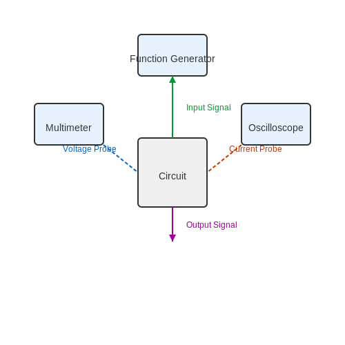
4.3 Maintaining Breadboard Integrity
In advanced electronics prototyping, maintaining the integrity of the breadboard is essential for ensuring reliable circuit performance. This involves managing both the physical condition of the breadboard and the electrical characteristics of connections.
Physical Integrity of the Breadboard
A breadboard consists of a matrix of interconnecting strips of metal that create a grid for inserting electronic components. Over time, the metal connectors can lose their elasticity due to repeated insertion and removal of components, leading to unreliable connections. To maintain the physical integrity of a breadboard:
- Avoid Excessive Force: When inserting components, apply gentle pressure to prevent damage to the internal connections.
- Regularly Clean the Surface: Dust and debris can compromise conductive pathways. Using isopropyl alcohol and a lint-free cloth can help keep the breadboard clean.
- Rotate Components: Change the orientation of components regularly to distribute wear evenly across the breadboard connections.
Electrical Integrity Considerations
Besides physical maintenance, paying attention to the electrical pathways is equally crucial. Overloading sections of a breadboard can lead to increased resistance and potential failure. To safeguard electrical integrity:
- Check Connection Quality: Use a multimeter to periodically test resistance across connections. This can help identify worn-out pathways before they cause failures.
- Limit Current Flow: Calculate the expected current loads carefully and ensure that they do not exceed the breadboard’s rated capacity, typically around a few amps.
- Use Appropriate Voltage Levels: Exceeding the rated voltage can lead to breakdown of the breadboard material, thus compromising connections and safety.
Practical Applications of Proper Maintenance
Maintaining breadboard integrity is not only a matter of prolonged usage but also of achieving consistency in experimental results, especially in sensitive applications such as:
- Signal Processing Circuits: Variations in component connectivity can lead to erratic signals.
- Test Measurements: Accurate data acquisition is reliant on stable connections across the test setup.
- Prototyping Complex Systems: For advanced systems like microcontroller-based designs, a malfunction in any part can lead to cascading failures in interconnected components.
By recognizing and maintaining both the physical and electrical attributes of breadboards, engineers and researchers can ensure their prototypes function accurately and consistently, thereby enhancing the reliability of the final designs.
5. Prototyping for Electronics Projects
5.1 Prototyping for Electronics Projects
Prototyping stands at the intersection of theory and practice in electronics development, serving as a critical phase where concepts are translated into functional designs. This section delves into advanced techniques and best practices for effective breadboarding—an essential skill for engineers and researchers working on electronic circuits.
Understanding the Breadboard
A breadboard provides a temporary platform for assembling electronic circuits without soldering. By allowing components to be easily inserted and removed, it facilitates rapid iteration. Components connect via metal strips beneath the board, which are arranged in a grid pattern, typically allowing for a multitude of configurations.
Types of Breadboards
- Solderless Breadboards: Widely used for prototyping, they allow components to be fit into a socket without soldering, fostering a rapid testing environment.
- Specialty Breadboards: These include versions tailored for specific applications such as Arduino or Raspberry Pi, which integrate additional features like power rails and mounting points.
- Custom Breadboard: Engineers often design custom breadboards for unique circuit configurations, which can streamline testing specific designs.
Configuration Techniques
Before diving into component placement, it's critical to understand how to best utilize the breadboard's layout. A systematic approach not only promotes clarity but also aids troubleshooting.
Power Distribution
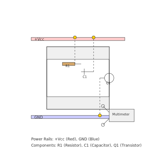
At the core of any electronics project is a reliable power distribution system. All breadboards typically feature two power rails running the length of the board, designated for positive and negative voltage supply. When beginning a project, it is essential to connect power supplies consistently.
Component Layout
When positioning components, a strategic layout can make a significant difference in debugging and modifying your circuit. Consider these guidelines:
- Group Components: Place related components physically close together. For instance, keep resistors near their corresponding capacitors or transistors.
- Signal Routing: Utilize straight paths for connections, avoiding unnecessary twists and turns which can lead to confusion.
- Labeling: Use labeling for power, input, and output connections to streamline communication, especially in complex circuits.
Testing and Debugging
Once the prototype is assembled, the following testing processes should be employed to verify functionality:
- Static Testing: Before applying power, conduct an inspection of the connections for any potential errors.
- Dynamic Testing: Use multimeters or oscilloscopes to monitor electrical characteristics, ensuring that components are operating under designed parameters.
- Iterative Modifications: Be prepared to make adjustments as inconsistencies arise, which is an inherent part of the prototyping phase.
Moreover, iterative testing informs the redesign process and leads to enhanced performance in the final product. The ability to prototype quickly helps in rapidly developing solutions to unexpected issues or design flaws.
Real-World Application: Case Study
The development of medical devices often begins on a breadboard. For instance, a team working on a portable ECG (electrocardiogram) machine will initially prototype the analog front-end circuit on a breadboard. This allows for testing sensitivity to noise, power consumption, and overall ergonomics before moving on to final PCB layouts. The iterative nature of breadboarding helps ensure that the final product is both functional and reliable.
In conclusion, effective prototyping through the use of breadboards plays a pivotal role in the electric circuit design process. Understanding best practices in component arrangement, power distribution, and testing procedures not only enhances project outcomes but also hones engineering skills by fostering a systematic approach to electronic design.
5.2 Educational Uses in Learning
Applied breadboarding serves as a powerful pedagogical tool in the domains of electronics and physics. Understanding the practical applications of breadboarding not only enhances theoretical knowledge but also cultivates hands-on skills essential for engineers and researchers. This section endorses the view that breadboarding is paramount in bridging the gap between conceptual learning and practical application, establishing a deeper understanding of fundamental principles.
Connecting Theory with Practice
At its core, breadboarding facilitates the tangible exploration of complex electronic theories. For instance, complex circuit configurations can be constructed without the permanence of soldering, allowing students to prototype and modify designs swiftly. This iterative process is crucial for enhancing critical thinking as students assess circuit behavior in real-time and refine their designs accordingly.
Fostering Innovation and Creativity
Furthermore, breadboarding encourages students to experiment beyond standard curricula. The ability to rapidly assemble circuits promotes innovation, as students feel empowered to test unconventional ideas or integrate interdisciplinary projects, such as combining electronics with robotics or computer science. Such cross-pollination of ideas mirrors real-world engineering scenarios where multifaceted problems require creative solutions.
Developing Debugging Skills
Inadequate testing methodologies often lead to faulty prototypes and setbacks. Breadboarding offers a hands-on approach to troubleshooting; students learn to identify errors in component placement, connections, and circuitry logic. This excursive learning experience imparts valuable debugging skills critical for any engineering professional, enhancing their capacity to diagnose issues under variable conditions.
Visual Learning and Conceptual Clarity
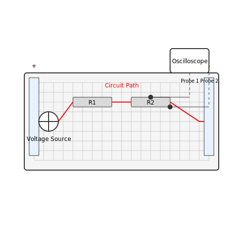
The visual nature of breadboarding aligns well with established educational theories that advocate for multimodal learning approaches. Students can observe voltage levels and phase relationships using oscilloscopes, which not only reinforces their understanding of theoretical constructs but also sharpens their observational skills. For example, rather than solely reading about Ohm's Law, students actively experiment with resistances, currents, and voltage drops, allowing for a more profound comprehension of relationships articulated by the law.
Here, \\(V\\) represents the voltage (volts), \\(I\\) denotes current (amperes), and \\(R\\) signifies resistance (ohms). This relationship becomes more practical when students actively manipulate resistors on a breadboard, generating real-time data and experiencing firsthand the implications of theoretical principles.
Case Studies and Practical Applications
Several institutions have successfully integrated breadboarding into their curricula. Institutions such as Stanford University have implemented lab courses focusing on rapid prototyping techniques, significantly improving student engagement and retention of complex concepts. Graduates have reported enhanced confidence in their technical abilities and a smoother transition into professional environments where rapid prototyping is a daily norm.
In summary, the educational uses of applied breadboarding extend beyond mere assembly; they encapsulate a holistic approach to learning that meshes academic theory with practical engineering skills, essential for fostering the next generation of innovators and problem-solvers.
5.3 Professional Applications in Product Development
In contemporary electronics design and engineering, breadboarding serves as a crucial step in the product development cycle. It enables engineers to prototype, test, and iterate on concepts rapidly without committing to more permanent solutions. This subsection explores various professional applications of breadboarding within product development, focusing on its practical relevance in both consumer electronics and highly specialized fields such as medical devices and aerospace systems.
Prototyping Innovative Electronics
The ability to quickly prototype circuits is perhaps one of the most significant advantages of breadboarding. Engineers can test various configurations of components such as resistors, capacitors, and integrated circuits rapidly. As a result, they can observe the intended functionality in real-time, making adjustments to circuit parameters and layouts.
For example, in consumer electronics, companies like Apple and Samsung utilize breadboards to evaluate new product ideas, such as novel user interfaces or advanced sensor integration, before finalizing the design. The iterative process allows for real-time user feedback, leading to enhanced user experience and product feasibility.
Implementation in Rapid Prototyping Environments
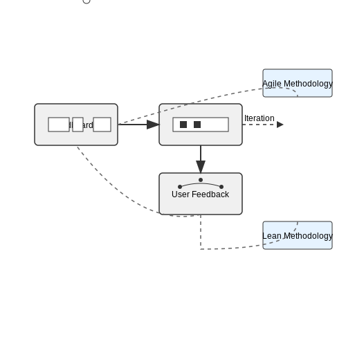
Modern product development increasingly adopts methodologies such as Agile and Lean, which encourage iterative development and rapid prototyping. Breadboarding allows teams to embrace these methodologies by providing a flexible platform for testing and validating concepts with ease.
For instance, a development team deploying Agile methodologies may utilize breadboards during sprint reviews to demonstrate working prototypes of their latest features. This interaction not only improves internal communication but also creates a feedback loop with stakeholders, directly influencing the final product outcome.
Industry-Specific Applications
Beyond consumer products, breadboarding plays a vital role in specialized fields. In medical device development, engineers often create prototypes of wearable health monitors that incorporate sensors for real-time data tracking. During the design process, engineers can explore various sensor configurations on a breadboard, decoding the complexities of biomedical signals before finalizing a PCB design.
In aerospace, the stakes are even higher, with strict regulations and safety standards. Engineers utilize breadboards to simulate the control systems directly controlling flight dynamics. Rigorous testing on a breadboard allows engineers to identify and rectify potential failures early in the design process, mitigating risks before full-scale production.
Educational and Research Applications
Another critical aspect of breadboarding is its usability in academic and research settings. Graduate students and researchers often use breadboards for experimentation, proving hypotheses, and demonstrating principles of electronics. The flexibility of breadboarding allows students to engage in hands-on learning, thereby solidifying theoretical knowledge through practical application.
Moreover, research initiatives aimed at developing cutting-edge technological innovations, such as IoT devices or AI-based systems, frequently rely on breadboarding. It allows researchers to explore complex interactions between hardware and software, facilitate testing and troubleshooting, and ultimately refine their prototypes. This practice emphasizes the importance of iterative design in advancing technology and products.
Conclusion
In summary, breadboarding serves as an indispensable tool in professional product development, fostering innovation and facilitating rigorous testing across various industries. Whether in consumer electronics, medical devices, aerospace, or academia, the versatility and efficiency of breadboarding empower engineers and researchers to push the boundaries of technology while ensuring reliability and safety.
6. Books on Breadboarding Techniques
6.1 Books on Breadboarding Techniques
- Practical Electronics for Inventors — This is a comprehensive guide to electronics, including detailed discussions on breadboarding. It covers essential topics in analog and digital electronics, complemented by practical experiments and illustrations.
- Make: Electronics — This book introduces electronics through engaging hands-on projects, with a focus on breadboarding as a primary method for prototyping and experimentation.
- The Illustrated Beginner's Guide to Electronics — A book designed for newcomers and intermediate users, offering projects and explanations about circuits on a breadboard, utilizing a visual approach to learning.
- Basics of Electronics — This text covers foundational electronic principles and provides practical examples, including breadboarding exercises that help solidify the learning process.
- The Art of Electronics — Widely considered a definitive guide, this book delves into the nuances of electronic circuits with practical insights on breadboarding techniques and design strategies.
- Electronics For Dummies — A user-friendly introduction to electronics, complete with breadboarding tips and tricks, offering both newcomers and experienced users useful guidance in a straightforward style.
- Analog Electronics — Focused on the principles of analog electronics, this book includes practical breadboarding applications that help in understanding complex circuit behavior through real-world examples and hands-on projects.
6.2 Online Resources and Tutorials
- SparkFun: Using a Breadboard — This comprehensive guide by SparkFun offers insights into breadboard basics, including connections and layout. It provides essential tips for both beginners and advanced users to build more efficient circuits.
- All About Circuits: Getting Started with Breadboards — This resource explains the fundamental concepts of breadboarding with detailed projects and examples, making it a great tool for advancing your prototype design skills.
- Electronics Tutorials: Breadboard Basics — A deep dive into how breadboards work, from pinouts to the internal structure. This site walks both novices and experts through advanced breadboarding concepts.
- YouTube: Breadboarding for Advanced Users — A video tutorial designed for advanced users, offering practical tips and demonstrations on advanced breadboarding techniques and troubleshooting.
- Circuit Basics: 8 Common Breadboarding Mistakes — This webpage highlights frequent errors encountered in breadboarding and offers solutions, making it easier for engineers to refine their prototyping skills.
- Amazon Kindle: Breadboarding Practice for DIY Electronics Projects — A detailed eBook offering advanced breadboarding strategies and projects, tailored for dedicated hobbyists and professionals seeking extensive practice.
- Instructables: How to Breadboard Advanced Projects — Instructables offers a plethora of innovative project ideas for advanced breadboard applications, guiding users through complex designs with images and step-by-step instructions.
- Mouser Electronics: Breadboards Design Tools & Tutorials — This page aggregates various tutorials and tools for breadboard designing, perfect for researchers and engineers wanting to perfect their breadboarding craftsmanship.
6.3 Research Papers on Circuit Prototyping
- Design and Application of a Modular Breadboard-Based System for Rapid Prototyping — Explores innovative modular breadboard systems for rapid prototype development in electronic circuits, offering insights into efficient design processes.
- Rapid Prototyping for Electromechanical Devices — Discusses the use of rapid prototyping techniques in designing electromechanical devices, underscoring the integration of breadboards in experimental setups.
- Using Breadboards to Teach Circuit Prototyping Skills — A valuable resource focusing on educational techniques using breadboards to enhance circuit prototyping skills among engineering students.
- Developing Breadboard Prototypes for Wireless Sensor Networks — Investigates the use of breadboards in developing prototypes for wireless sensor network applications, highlighting practical advantages and challenges.
- Prototyping Techniques for Embedded Systems — Provides a comprehensive review of various prototyping techniques within embedded systems design, emphasizing the role of breadboards in the iterative process.
- Circuit Prototyping for Control Applications: A Practical Approach — Offers a practical guide to circuit prototyping specifically for control applications, detailing breadboard usage and performance assessment.
- Modern Trends in Circuit Prototyping — Analyzes current trends in circuit prototyping, providing insights into the integration of breadboards with software tools to streamline the design process.