Resistor Tutorial
1. Definition and Purpose of Resistors
1.1 Definition and Purpose of Resistors
A resistor is a passive two-terminal electrical component that implements electrical resistance as a circuit element. Its fundamental property is opposition to the flow of electric current, quantified by Ohm's Law:
where V is the voltage across the resistor, I is the current through it, and R is its resistance value measured in ohms (Ω). This linear relationship holds for ideal resistors under all conditions, though real resistors exhibit additional parasitic properties at high frequencies or extreme temperatures.
Microscopic Origin of Resistance
At the atomic scale, resistance arises from electron scattering by lattice vibrations (phonons), impurities, and defects in the material. The resistivity ρ of a homogeneous material relates to its macroscopic resistance by:
where L is the length of the conductor and A is its cross-sectional area. For non-ideal cases, resistivity becomes temperature-dependent:
with α being the temperature coefficient of resistivity, which is positive for metals and negative for semiconductors.
Key Functional Roles
Resistors serve multiple critical functions in electronic circuits:
- Current limiting: Protect sensitive components by restricting current flow, as in LED driver circuits.
- Voltage division: Create reference voltages through resistive dividers, essential for biasing transistors and ADCs.
- Power dissipation: Convert electrical energy into heat in controlled manner, used in braking systems and dummy loads.
- Impedance matching: Minimize signal reflections in RF circuits by matching source and load impedances.
- Signal conditioning: Shape frequency response in combination with capacitors/inductors (RC/RL filters).
Non-Ideal Characteristics
Practical resistors exhibit several second-order effects that become significant in precision applications:
- Parasitic inductance (L): Wirewound resistors exhibit significant series inductance (nH to μH range).
- Parasitic capacitance (C): Distributed capacitance between turns or terminals (pF range).
- Voltage coefficient: Resistance variation with applied voltage, particularly in thick-film resistors.
- Noise: Thermal (Johnson-Nyquist) noise and current-dependent (excess) noise contributions.
The total impedance Z of a real resistor at frequency ω can be modeled as:
Material Technologies
Different resistor types are optimized for specific applications:
| Type | Composition | Tolerance | Temp. Coeff. (ppm/°C) |
|---|---|---|---|
| Carbon Film | Carbon/polymer | 5% | 250-1000 |
| Metal Film | NiCr/TaN | 1% | 50-100 |
| Foil | Cu-Ni alloy | 0.005% | 0.2-2 |
| Wirewound | Manganin | 0.1% | 10-50 |
1.2 How Resistors Work: Basic Principles
Fundamental Mechanism of Resistance
Resistance arises from the interaction between charge carriers (typically electrons) and the atomic lattice of a material. In conductors, electrons move under an applied electric field, but their motion is impeded by collisions with lattice ions, impurities, and thermal vibrations. The macroscopic effect is quantified by Ohm's Law:
where V is voltage, I is current, and R is resistance. At a microscopic level, resistance depends on the material's resistivity (ρ), length (L), and cross-sectional area (A):
Quantum Mechanical Perspective
In quantum terms, resistance emerges from electron scattering. The mean free path (λ) of electrons—determined by lattice imperfections and phonon interactions—directly influences resistivity. For metals, Matthiessen's Rule decomposes resistivity into temperature-dependent (phonon) and temperature-independent (impurity) components:
At low temperatures, ρphonon vanishes, revealing the residual resistance ratio (RRR), a key metric for material purity.
Thermal Effects and Noise
Resistors exhibit Johnson-Nyquist noise due to thermal agitation of charge carriers, with spectral noise density given by:
where kB is Boltzmann's constant, T is temperature, and Δf is bandwidth. This limits precision in high-gain circuits.
Frequency-Dependent Behavior
At high frequencies, parasitic inductance (L) and capacitance (C) dominate, forming an RLC network. The impedance (Z) becomes complex:
This necessitates careful modeling in RF applications, where skin effect further increases effective resistance.
Nonlinear and Specialized Resistors
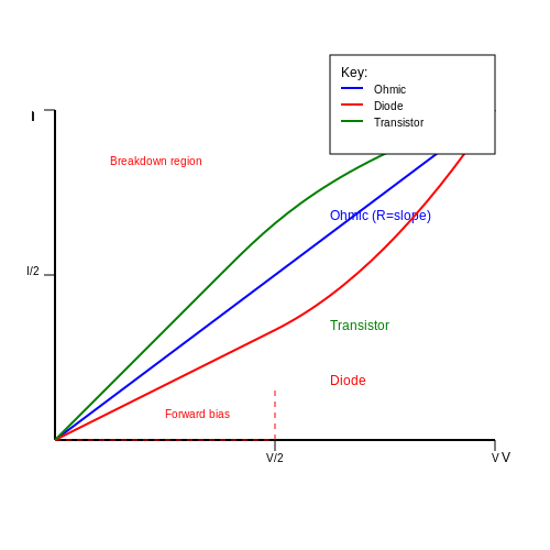
Some resistors exhibit nonlinear I-V characteristics:
- Varistors: Voltage-dependent resistance for surge protection.
- Thermistors: Temperature-sensitive resistance (NTC/PTC types).
- Memristors: Resistance depends on charge history, enabling neuromorphic computing.
Practical Considerations
In circuit design, power dissipation (P = I²R) dictates resistor sizing. Pulse handling requires derating based on thermal mass. Precision resistors (e.g., Vishay Bulk Metal Foil) achieve ±0.001% tolerance with TCRs below 0.1 ppm/°C for metrology applications.
Units of Resistance: Ohms (Ω)
The Fundamental Definition
The ohm (Ω), the SI unit of electrical resistance, is defined as the resistance between two points in a conductor when a constant potential difference of 1 volt applied across them produces a current of 1 ampere. This relationship is derived directly from Ohm's Law:
where R is resistance in ohms, V is voltage in volts, and I is current in amperes. The dimensional analysis reveals that:
Quantum Resistance and the von Klitzing Constant
In mesoscopic systems and quantum Hall effect research, resistance becomes quantized. The quantum resistance unit is given by:
where h is Planck's constant and e is the elementary charge. This fundamental constant provides an absolute resistance standard traceable to quantum mechanical principles rather than material artifacts.
Practical Realization and Standards
The ohm is maintained through quantum Hall resistance standards in national metrology institutes. A practical realization involves:
- GaAs/AlGaAs heterostructures at cryogenic temperatures (~1.5 K)
- Magnetic fields of ~10 Tesla
- Precision current sources with 10⁻⁸ relative uncertainty
Modern resistance standards achieve reproducibility better than 0.02 ppm, enabling calibration of working standards used in industry and research.
Common Multiples and Submultiples
Resistance values span over 30 orders of magnitude in practice:
| Prefix | Symbol | Magnitude | Typical Applications |
|---|---|---|---|
| microohm | μΩ | 10⁻⁶ Ω | Contact resistance measurements |
| milliohm | mΩ | 10⁻³ Ω | Current shunt resistors |
| kiloohm | kΩ | 10³ Ω | Voltage dividers |
| megaohm | MΩ | 10⁶ Ω | Insulation testing |
| gigaohm | GΩ | 10⁹ Ω | Electrometer circuits |
Temperature Dependence and Material Properties
The resistance of materials varies with temperature according to:
where α is the linear temperature coefficient of resistance (TCR) and β accounts for nonlinear effects. For precision resistors:
- Metal film: α ≈ ±5 ppm/°C to ±50 ppm/°C
- Bulk metal foil: α ≈ ±0.2 ppm/°C to ±2 ppm/°C
- Carbon composition: α ≈ -500 ppm/°C to +1200 ppm/°C
Noise Considerations
Resistors generate thermal (Johnson-Nyquist) noise with spectral density:
where kB is Boltzmann's constant and Δf is the bandwidth. For a 1 kΩ resistor at 300 K in a 1 Hz bandwidth, this amounts to approximately 4 nV/√Hz.
2. Fixed Resistors
2.1 Fixed Resistors
Fixed resistors are passive electronic components designed to introduce a predetermined resistance into a circuit, opposing current flow in a precisely controlled manner. Unlike variable resistors, their resistance remains constant under normal operating conditions, making them fundamental in biasing, signal conditioning, and power dissipation applications.
Material Composition and Construction
Fixed resistors are categorized based on their material composition and manufacturing techniques:
- Carbon Composition: Early resistors composed of carbon particles mixed with a binder. Exhibited high noise and poor stability but were widely used in mid-20th-century electronics.
- Carbon Film: A carbon layer deposited on a ceramic substrate, laser-trimmed to precise values. Offers improved tolerance (±5%) and lower noise compared to carbon composition.
- Metal Film: Thin metal (often nickel-chromium or tantalum nitride) deposited via sputtering. Provides tight tolerances (±1% or better), low temperature coefficients (50 ppm/°C), and superior stability.
- Metal Oxide Film: Similar to metal film but uses oxidized metals for higher power handling and surge resistance.
- Wirewound: A resistive wire (e.g., nichrome) wound around a core, used for high-power applications. Inductive behavior limits high-frequency use.
- Foil Resistors: Precision components with near-zero temperature coefficients (±1 ppm/°C), used in metrology and instrumentation.
Mathematical Characterization
The resistance R of a fixed resistor is determined by its geometry and material resistivity ρ:
where L is the conductive path length and A is the cross-sectional area. For thin-film resistors, sheet resistance Rs (in Ω/□) simplifies calculations:
where W is the film width.
Parasitic Effects and Non-Ideal Behavior
Real fixed resistors exhibit parasitic properties that become significant at high frequencies or precision applications:
- Parasitic Inductance: Wirewound and thick-film resistors suffer from self-inductance due to helical current paths.
- Parasitic Capacitance: Inter-electrode capacitance (1–5 pF) affects high-frequency impedance.
- Temperature Coefficient of Resistance (TCR): Expressed as:
Metal film resistors typically achieve TCRs below 100 ppm/°C, while foil resistors reach sub-ppm levels.
Power Derating and Thermal Considerations
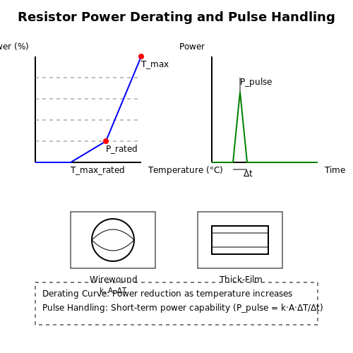
The maximum power dissipation Pmax is specified at 25°C and must be derated at elevated temperatures. For example, a 1 W resistor follows:
where Tmax is the maximum operating temperature (often 155°C for metal film).
Practical Selection Criteria
Engineers prioritize parameters based on application:
- Precision Circuits: Metal film or foil resistors with ±0.1% tolerance and low TCR.
- High-Frequency Systems: Non-inductive thin-film or carbon composition types.
- Power Electronics: Wirewound or metal oxide resistors with adequate heat sinking.
2.2 Variable Resistors (Potentiometers and Rheostats)
Fundamental Operation and Construction
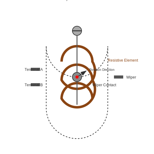
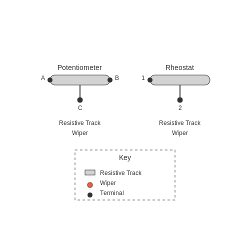
Variable resistors are passive components designed to provide adjustable resistance in a circuit. The two primary types are potentiometers (pots) and rheostats, differentiated by their terminal configurations and applications. A potentiometer is a three-terminal device with a resistive track and a sliding contact (wiper), allowing voltage division. A rheostat, typically a two-terminal device, functions as an adjustable resistor, often used for current control.
The resistance R of a potentiometer is distributed along a conductive track, with the wiper position x (normalized between 0 and 1) determining the output voltage Vout:
Mathematical Derivation of Taper Laws
Potentiometers follow a taper law, defining how resistance varies with wiper position. Linear taper potentiometers exhibit a direct proportionality:
Logarithmic (audio) and anti-logarithmic tapers use exponential relationships, modeled as:
Rheostats and Power Dissipation
Rheostats, often wire-wound for high-power applications, dissipate power as heat. The power rating P must satisfy:
where I is the current through the rheostat. Failure to adhere to this limit risks thermal runaway.
Practical Applications
- Potentiometers: Volume controls (log taper), sensor calibration (linear taper), voltage dividers in op-amp feedback networks.
- Rheostats: Motor speed control, dimmer circuits (historically), laboratory current limiting.
Non-Ideal Behavior and Compensation
Real-world variable resistors exhibit:
- Contact Resistance: Wiper-to-track resistance introduces nonlinearity, mitigated via gold-plated contacts in precision pots.
- Temperature Coefficients: TCR (Temperature Coefficient of Resistance) affects stability; cermet and conductive plastic tracks offer lower TCR than carbon.
2.3 Specialized Resistors (Thermistors, LDRs, etc.)
Thermistors: Temperature-Dependent Resistors
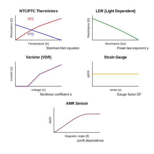
Thermistors exhibit a highly nonlinear resistance-temperature relationship, making them ideal for precision temperature sensing. Their behavior is governed by the Steinhart-Hart equation:
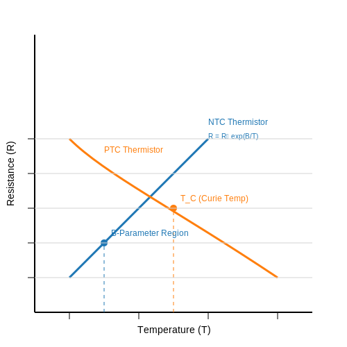
where T is temperature in Kelvin, R is resistance, and A, B, C are device-specific coefficients. Negative temperature coefficient (NTC) thermistors decrease resistance with rising temperature, while positive temperature coefficient (PTC) variants exhibit the opposite behavior.
Practical applications include:
- Medical-grade temperature monitoring with ±0.1°C accuracy
- Inrush current limiting in power supplies (PTC types)
- Battery pack thermal management in EVs
Light-Dependent Resistors (LDRs)
LDRs utilize photoconductive materials like cadmium sulfide (CdS) or lead sulfide (PbS) whose resistance varies with incident light intensity. The response follows an approximate power law:
where E is illuminance and γ ranges from 0.7 to 0.9 for CdS cells. Key performance metrics include:
- Dark resistance (typically 1-10 MΩ)
- Response time (10-100 ms for CdS)
- Spectral sensitivity peaking at 520-620 nm
Modern applications span from automatic street lighting to precision spectrophotometry, though they're being gradually replaced by photodiodes in high-speed applications.
Varistors and Voltage-Dependent Resistors
Metal-oxide varistors (MOVs) provide nonlinear voltage clamping through their polycrystalline ZnO structure. The V-I characteristic follows:
where α typically ranges 20-50. Key parameters include:
- Clamping voltage (18V to 1kV ranges)
- Energy absorption (0.1 to 10 kJ)
- Response time (< 25 ns)
They serve critical roles in:
- Transient voltage suppression (IEC 61000-4-5 compliance)
- Power line surge protection
- ESD protection in high-speed circuits
Strain Gauges and Piezoresistive Effects
Strain gauges exploit the piezoresistive effect where mechanical deformation alters a material's resistivity. The gauge factor GF quantifies sensitivity:
where ϵ is strain. Metal foil gauges achieve GF ≈ 2, while semiconductor types reach 100-200. Wheatstone bridge configurations enable microstrain (με) resolution. Applications include:
- Structural health monitoring in civil engineering
- Force/torque sensors in robotics
- Microelectromechanical systems (MEMS) accelerometers
Magnetoresistors and Spintronic Variants
Magnetoresistive materials exhibit resistance changes under magnetic fields. The anisotropic magnetoresistance (AMR) effect follows:
where θ is the angle between current and magnetization. Giant magnetoresistance (GMR) and tunneling magnetoresistance (TMR) devices now enable:
- Hard drive read heads with areal densities > 1 Tb/in²
- Non-contact angle sensors with 0.01° resolution
- Magnetic random-access memory (MRAM) cells
3. Standard Color Code Chart
3.1 Standard Color Code Chart
The resistor color code is a standardized system used to denote the resistance value, tolerance, and sometimes temperature coefficient of axial-lead resistors. The system employs a sequence of colored bands, each representing a specific numerical value or multiplier. For precision applications, additional bands may indicate reliability or thermal characteristics.
Four-Band vs. Five-Band vs. Six-Band Coding
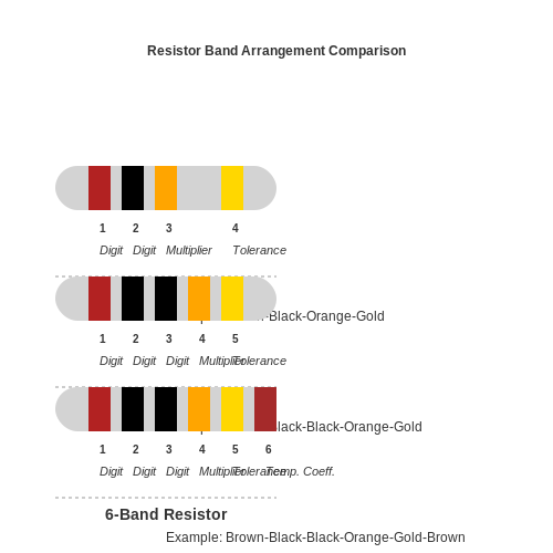
Resistors typically use four, five, or six bands, with each variation providing increasing levels of detail:
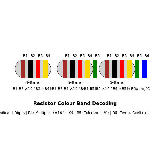
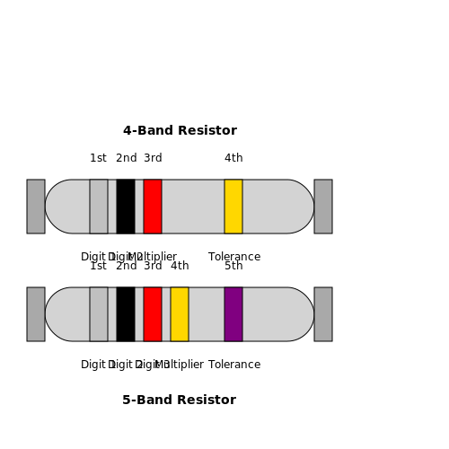
- Four-band resistors: The first two bands represent significant digits, the third is the multiplier, and the fourth indicates tolerance.
- Five-band resistors: The first three bands are significant digits, the fourth is the multiplier, and the fifth is tolerance. This allows for higher precision.
- Six-band resistors: Adds a temperature coefficient (ppm/°C) as the sixth band, critical in high-stability applications.
Color-to-Value Mapping
The following table describes the standard color assignments:
| Color | Digit | Multiplier | Tolerance | Temp. Coeff. (ppm/°C) |
|---|---|---|---|---|
| Black | 0 | 100 | — | 250 |
| Brown | 1 | 101 | ±1% | 100 |
| Red | 2 | 102 | ±2% | 50 |
| Orange | 3 | 103 | — | 15 |
| Yellow | 4 | 104 | — | 25 |
| Green | 5 | 105 | ±0.5% | 20 |
| Blue | 6 | 106 | ±0.25% | 10 |
| Violet | 7 | 107 | ±0.1% | 5 |
| Gray | 8 | 108 | ±0.05% | — |
| White | 9 | 109 | — | — |
| Gold | — | 10-1 | ±5% | — |
| Silver | — | 10-2 | ±10% | — |
Practical Interpretation Example
Consider a five-band resistor with colors Yellow, Violet, Black, Red, Brown:
- First three bands (Yellow, Violet, Black): 4, 7, 0 → 470
- Fourth band (Red): Multiplier of 102 → 470 × 100 = 47 kΩ
- Fifth band (Brown): Tolerance of ±1%
Thus, the resistor value is 47 kΩ ±1%.
Special Cases and Exceptions
Military-spec resistors (MIL-PRF-55342) may use an additional band for failure rate. Zero-ohm resistors, often used as jumpers, are denoted by a single black band.
where \(d_1, d_2\) are significant digits and \(m\) is the multiplier exponent.
Historical Context
The color code system was formalized in the 1920s by the Radio Manufacturers Association (now part of EIA) to standardize resistor identification. Prior methods included numerical stamps, which were impractical for small components.
Reading 4-Band and 5-Band Resistors
Color Code System Fundamentals
The resistor color code system, standardized by IEC 60062, provides a compact method for indicating resistance values and tolerances. Each color corresponds to a specific digit, multiplier, or tolerance value. The system's origins trace back to the 1920s when the increasing miniaturization of components made numerical printing impractical.
For 4-band resistors, the first two bands represent significant digits, the third is the multiplier, and the fourth indicates tolerance. 5-band resistors add an additional significant digit for improved precision, with the first three bands as digits, the fourth as multiplier, and the fifth as tolerance.
Decoding 4-Band Resistors
The resistance value R of a 4-band resistor is calculated as:
where d₁ and d₂ are the first two digits, m is the multiplier exponent, and t is the tolerance percentage. Consider a resistor with color bands Yellow (4), Violet (7), Red (10²), and Gold (±5%):
Decoding 5-Band Resistors
5-band resistors follow a similar convention but with higher precision:
For a resistor with bands Brown (1), Black (0), Black (0), Orange (10³), and Brown (±1%):
Tolerance and Reliability Considerations
The tolerance band indicates the maximum allowable deviation from the nominal value. Common tolerance colors include:
- Gold: ±5% (general purpose)
- Silver: ±10% (older or less critical applications)
- Brown: ±1% (precision applications)
- Red: ±2%
- Green/Blue/Violet: ±0.5%/±0.25%/±0.1% (high-precision)
In military and aerospace applications, resistors often include an additional band indicating reliability (failure rate per 1000 hours of operation).
Practical Measurement Verification
When working with high-precision circuits, always verify resistor values with a calibrated multimeter. Consider the following error sources:
- Parasitic inductance in leaded resistors above 1MHz
- Temperature coefficient effects (indicated by additional bands in some models)
- Voltage coefficient in high-voltage applications
For surface-mount resistors, the alphanumeric EIA-96 code system is typically used instead of color bands, though some manufacturers still employ color coding for larger packages.
3.3 Tolerance and Temperature Coefficient
Resistor Tolerance
The tolerance of a resistor defines the permissible deviation from its nominal value, expressed as a percentage. For example, a 1 kΩ resistor with a 5% tolerance may have an actual resistance between 950 Ω and 1050 Ω. High-precision resistors, such as those used in medical or aerospace applications, may have tolerances as tight as 0.1% or better. The tolerance is determined during manufacturing and is influenced by material uniformity, deposition accuracy, and trimming processes.
The statistical distribution of resistor values within a batch typically follows a Gaussian distribution centered around the nominal value. For a ±5% tolerance, 99.7% of resistors should fall within three standard deviations of the mean. However, real-world distributions may exhibit skewness due to process variations.
Temperature Coefficient of Resistance (TCR)
The Temperature Coefficient of Resistance (TCR) quantifies how a resistor's value changes with temperature, defined as:
where R0 is the nominal resistance at a reference temperature (usually 25°C) and dR/dT is the rate of change of resistance with temperature. TCR is expressed in parts per million per degree Celsius (ppm/°C). For example, a TCR of 100 ppm/°C means the resistance changes by 0.01% per °C.
The TCR of a resistor depends on its material composition:
- Carbon composition: High TCR (≈1500 ppm/°C), highly nonlinear.
- Metal film: Low TCR (≈50–100 ppm/°C), nearly linear.
- Precision foil resistors: Ultra-low TCR (<1 ppm/°C), used in metrology.
Thermal Effects in Practical Circuits
In high-precision analog circuits, TCR-induced drift can introduce errors in voltage dividers, feedback networks, and sensor interfaces. For instance, in a Wheatstone bridge, unmatched TCRs between resistors create a temperature-dependent offset voltage:
To mitigate this, designers use resistors with matched TCRs or implement active temperature compensation. In power electronics, Joule heating exacerbates TCR effects, requiring derating or forced cooling for stability.
Advanced TCR Modeling
For critical applications, a second-order TCR model improves accuracy:
where α is the linear coefficient and β the quadratic coefficient. Thin-film resistors often exhibit a parabolic TCR curve, with β ranging from 0.1 to 5 ppm/°C2.
Case Study: Precision Voltage Reference
A 10.000 V reference using a 10 kΩ metal-film resistor with 50 ppm/°C TCR experiences a 5 mV shift over a 10°C temperature change. Replacing it with a 1 ppm/°C foil resistor reduces the drift to 0.1 mV, demonstrating the impact of TCR selection in metrology systems.
4. Current Limiting and Voltage Division
4.1 Current Limiting and Voltage Division
Fundamentals of Current Limiting
Resistors are fundamental in controlling current flow in electronic circuits. Ohm's Law governs this behavior:
where I is the current, V is the voltage, and R is the resistance. In a series circuit, the current through each component is identical, making resistors effective for limiting current to sensitive devices like LEDs. For instance, an LED with a forward voltage Vf and maximum current Imax requires a series resistor:
This ensures the LED operates within safe limits, preventing thermal runaway.
Voltage Division Principle
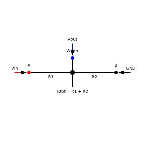
Resistors also enable precise voltage division, a cornerstone in analog circuit design. The voltage divider rule for two resistors R1 and R2 in series is derived from Kirchhoff's Voltage Law (KVL):
This relationship assumes negligible load current, as significant current draw alters the divider's effective resistance. For high-precision applications, Thévenin's theorem simplifies analysis by modeling the divider as a voltage source Vth = Vout with series resistance Rth = R1 || R2.
Practical Considerations
Non-ideal effects must be accounted for in advanced designs:
- Temperature dependence: Resistivity varies with temperature, quantified by the temperature coefficient of resistance (TCR).
- Power dissipation: Resistors must handle Joule heating P = I²R without exceeding their power rating.
- Frequency response: Parasitic capacitance and inductance affect performance at high frequencies.
Advanced Applications
Current limiting and voltage division underpin critical systems:
- Biasing networks: Stabilize transistor operating points in amplifiers.
- Sensor interfacing: Scale sensor outputs to ADC input ranges.
- Feedback loops: Set gain in operational amplifier circuits.
The diagram above illustrates a basic voltage divider. For dynamic loads, impedance matching ensures minimal signal reflection, critical in RF and transmission line applications.
4.2 Pull-Up and Pull-Down Resistors
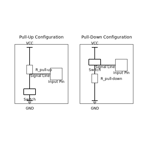
Pull-up and pull-down resistors are fundamental components in digital electronics, ensuring well-defined logic states in floating or high-impedance conditions. Their primary role is to bias an input signal to a known voltage level when no active driver is present, preventing undefined behavior in logic gates, microcontrollers, and communication buses.
Pull-Up Resistors
A pull-up resistor connects a signal line to the positive supply voltage (VCC), ensuring a default high logic level when the input is not actively driven low. The resistor value must be carefully selected to balance current consumption and noise immunity. Too low a resistance increases power dissipation, while too high a resistance makes the circuit susceptible to noise.
where:
- VIH is the minimum input voltage recognized as a logic high.
- IIH is the input leakage current.
Typical values range from 1kΩ to 10kΩ for 5V logic families like TTL and CMOS. For I2C buses, the resistor must satisfy the rise time requirement:
where tr is the maximum allowable rise time and Cb is the bus capacitance.
Pull-Down Resistors
Pull-down resistors connect a signal line to ground, ensuring a default low logic level when the input is not actively driven high. The resistor must be small enough to override leakage currents but large enough to avoid excessive power draw.
where:
- VIL is the maximum input voltage recognized as a logic low.
- IIL is the input leakage current.
Practical Considerations
In high-speed digital circuits, improper resistor selection can lead to signal integrity issues. For example, excessively large pull-up resistors in open-drain configurations increase RC time constants, degrading edge rates. Conversely, excessively small resistors increase power dissipation and may exceed driver current ratings.
In microcontroller applications, internal pull-up/pull-down resistors (often in the range of 20kΩ–50kΩ) are available but may lack precision. External resistors are preferred for critical timing or noise-sensitive applications.
Real-World Applications
- I2C and SMBus: Pull-up resistors set idle bus states and define logic levels.
- Button and Switch Debouncing: Pull-up/down resistors ensure a known state when the switch is open.
- Reset Circuits: Pull-up resistors maintain stable reset conditions until actively asserted.
For bidirectional buses like I2C, the pull-up resistor must account for the worst-case capacitive load:
where VOL is the maximum output low voltage and IOL is the driver’s sink current capability.
4.3 Filtering and Timing Circuits
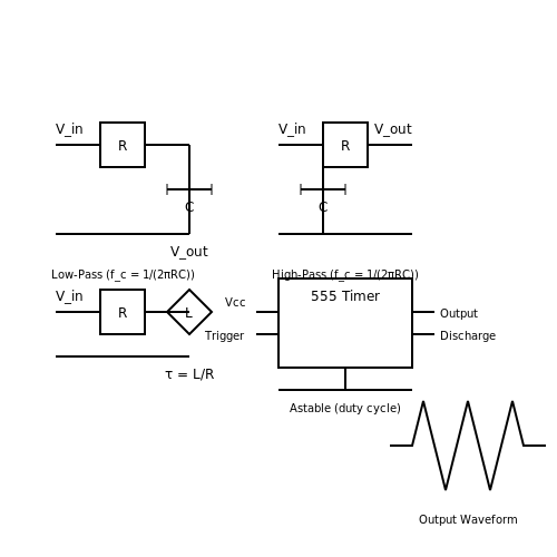
RC Low-Pass and High-Pass Filters
Resistors, combined with capacitors, form the backbone of first-order passive filters. The cutoff frequency fc of an RC filter is determined by:
For a low-pass filter, the resistor is placed in series with the input, while the capacitor shunts the output to ground. The transfer function H(s) in the Laplace domain is:
Conversely, a high-pass filter swaps the positions of R and C, yielding:
RL Filters and Quality Factor
When inductors replace capacitors, RL filters emerge. The quality factor Q for a series RL circuit is:
where ω0 is the resonant frequency. Higher Q indicates sharper roll-off but also increased susceptibility to component tolerances.
Timing Circuits and Pulse Shaping
In monostable and astable multivibrators, resistors control timing intervals. For a 555 timer in astable mode, the output frequency is:
Duty cycle adjustment requires precise resistor ratios. For pulse shaping, RC networks with time constants τ = RC modify rise/fall times, critical in digital signal integrity.
Higher-Order Active Filters
Sallen-Key and multiple-feedback topologies use resistors to set gain and cutoff frequencies. For a 2nd-order low-pass Sallen-Key filter:
Resistor matching (typically ≤1% tolerance) minimizes passband ripple. Active filters enable Q values unattainable with passive components alone.
Practical Considerations
- Thermal noise: Johnson-Nyquist noise (4kBTRB) limits dynamic range in high-impedance circuits
- Parasitics: Stray capacitance forms unintended filters with resistors >100kΩ
- Power rating: Pulse applications require derating to avoid thermal runaway
In RF applications, thin-film resistors exhibit lower parasitic inductance than carbon composition types. For precision timing, metal foil resistors provide optimal stability (±5ppm/°C).
5. Power Rating and Heat Dissipation
5.1 Power Rating and Heat Dissipation
The power rating of a resistor defines the maximum power it can safely dissipate without exceeding its thermal limits. This is determined by the resistor's material properties, physical size, and ambient operating conditions. Exceeding the rated power leads to excessive temperature rise, potentially causing catastrophic failure or parametric drift.
Thermal Derating and Maximum Operating Temperature
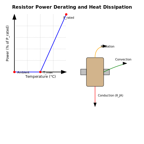
Resistors experience reduced power handling capability as ambient temperature increases. Manufacturers provide derating curves specifying the percentage of rated power that can be safely applied at elevated temperatures. The maximum operating temperature is typically 70-175°C for standard resistors, with military-grade components reaching up to 200°C.
where Trated is the temperature at which full power rating applies (usually 70°C), and Tmax is the absolute maximum temperature.
Heat Dissipation Mechanisms
Resistors dissipate heat through three primary mechanisms:
- Conduction: Heat transfer through physical contact with PCB or heatsink
- Convection: Airflow cooling dependent on surface area and orientation
- Radiation: Infrared emission proportional to the fourth power of absolute temperature
The thermal resistance (θJA) from junction to ambient characterizes overall heat dissipation capability. For surface-mount resistors, typical values range from 100-300°C/W, while power resistors may achieve 10-50°C/W with proper heatsinking.
Transient Power Handling
Resistors can temporarily withstand power surges exceeding their continuous rating due to thermal mass effects. The permissible overload depends on pulse duration and thermal time constant (τ):
where Rth is thermal resistance and Cth is thermal capacitance. For short pulses (<< τ), power handling may be 10-100x the continuous rating.
Practical Design Considerations
In high-power applications, designers must:
- Account for temperature coefficient of resistance (TCR) effects
- Consider thermal coupling between adjacent components
- Evaluate long-term reliability under thermal cycling conditions
- Implement derating factors (typically 50-80% of maximum rating) for safety margins
Power resistors often incorporate aluminum casings, heatsink mounting provisions, or forced air cooling to enhance dissipation. In precision circuits, temperature gradients across resistor bodies can introduce thermoelectric voltages exceeding 1μV/°C.
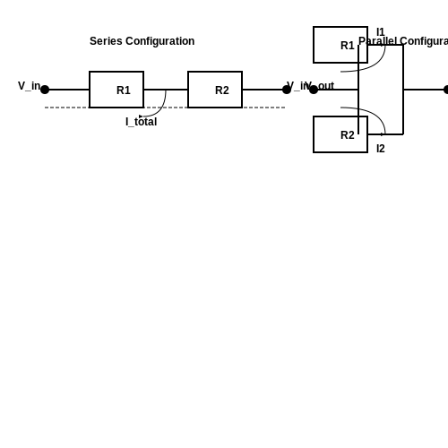
Series and Parallel Configurations
Resistors in Series
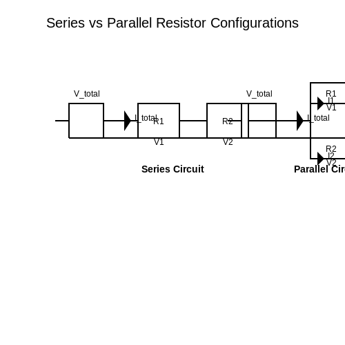
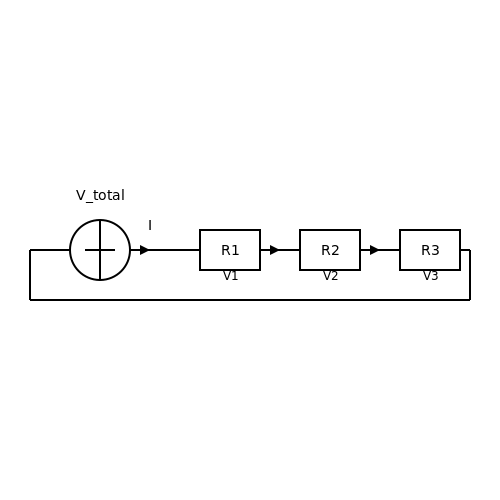
When resistors are connected in series, the same current flows through each resistor, while the total voltage is the sum of individual voltage drops. The equivalent resistance Req of N resistors in series is given by:
This additive property arises from Kirchhoff’s Voltage Law (KVL), which states that the sum of potential differences around a closed loop must be zero. In practical circuits, series configurations are often used for voltage division or current-limiting applications.
Resistors in Parallel
In a parallel configuration, resistors share the same voltage, while the total current is the sum of individual branch currents. The equivalent resistance Req for N parallel resistors follows the reciprocal sum rule:
For two resistors, this simplifies to:
Parallel arrangements are common in circuits requiring independent current paths, such as power distribution networks or shunt current measurement.
Current and Voltage Distribution
The behavior of series and parallel networks extends to current and voltage distribution:
- Series: Current is uniform; voltage divides proportionally to resistance.
- Parallel: Voltage is uniform; current divides inversely with resistance.
For example, in a voltage divider (series), the output voltage Vout across resistor R2 is:
Practical Implications
Real-world applications include:
- Series: Precision resistor chains in DACs (Digital-to-Analog Converters), where matching tolerances are critical.
- Parallel: Power dissipation sharing in high-current circuits, reducing thermal stress on individual components.
Non-ideal effects, such as parasitic inductance or capacitance, become significant at high frequencies, requiring careful PCB layout to maintain intended resistive behavior.
Derivation of Equivalent Resistance
The derivation for parallel resistors stems from Kirchhoff’s Current Law (KCL). For two resistors:
Since V = Itotal Req, substitution yields the reciprocal relationship.
Case Study: Mixed Configurations
Complex networks combine series and parallel elements. For instance, a ladder network’s equivalent resistance is solved by iterative simplification:
- Identify and collapse parallel/series sub-circuits.
- Recursively reduce the network until a single Req remains.
SPICE simulations often validate hand calculations, especially in circuits with >5 components.
5.3 Common Mistakes and Troubleshooting
Incorrect Power Rating Selection
A frequent error is underestimating the power dissipation in a resistor, leading to thermal failure. The power dissipated in a resistor is given by:
where P is power in watts, I is current in amperes, and R is resistance in ohms. Engineers often neglect to account for transient current spikes or RMS values in AC circuits, causing resistors to exceed their rated power. For pulsed applications, the transient thermal response must be considered, as the short-term power handling can differ significantly from the continuous rating.
Voltage Coefficient Effects
High-value resistors (typically above 1 MΩ) exhibit a voltage coefficient where resistance varies with applied voltage. This nonlinearity is often overlooked in precision circuits. The effect can be modeled as:
where R0 is the nominal resistance, V is the applied voltage, and αV is the voltage coefficient (typically in ppm/V). In high-voltage dividers or feedback networks, this can introduce unexpected gain errors.
Parasitic Inductance and Capacitance
All resistors exhibit parasitic elements that become significant at high frequencies. The impedance of a real resistor can be expressed as:
where L is lead inductance and C is parasitic capacitance. Carbon composition resistors show the least parasitic effects, while thin-film resistors may exhibit noticeable capacitive coupling at frequencies above 100 MHz. This is particularly problematic in RF circuits or fast-switching digital systems.
Thermal EMF and Noise
In precision DC applications, thermal EMFs generated at dissimilar metal junctions (e.g., resistor leads to PCB pads) can introduce offset voltages. For low-noise designs, the Johnson-Nyquist noise must be considered:
where kB is Boltzmann's constant, T is temperature in Kelvin, and Δf is bandwidth. Wirewound resistors, while stable, can generate microphonic noise in vibration-prone environments.
Soldering and Mechanical Stress
Excessive soldering heat can alter the resistance value, particularly in thin-film resistors. The temperature coefficient of resistance (TCR) becomes critical when:
where αT is TCR in ppm/°C. Mechanical stress from board flexure or improper mounting can also affect precision resistors, with strain gauge effects causing resistance variations up to 0.1% in extreme cases.
Troubleshooting Methodology
- Thermal Imaging: Use infrared cameras to identify hot spots indicating overstressed components.
- Four-Wire Kelvin Measurement: Eliminates lead resistance errors when measuring low resistances.
- Network Analyzer: Characterizes frequency-dependent behavior in RF applications.
- Noise Spectral Density: Measures Johnson and excess noise contributions.
Case Study: Precision Voltage Reference Failure
A 10 V reference circuit using 0.01% tolerance resistors showed 120 ppm drift after 6 months. Investigation revealed:
- Moisture ingress in conformal coating altered PCB surface resistance
- TCR mismatch between reference and divider resistors
- Thermal gradients causing Seebeck effect voltages
The solution involved hermetically sealed resistors with matched TCRs and symmetrical PCB layout to minimize thermal gradients.
6. Recommended Books and Articles
6.1 Recommended Books and Articles
- PDF Fundamentals of Electronic Circuit Design - University of Cambridge — Fundamentals of Electronic Circuit Design Outline Part I - Fundamental Principles 1 The Basics 1.1 Voltage and Current 1.2 Resistance and Power 1.3 Sources of Electrical Energy 1.4 Ground 1.5 Electrical Signals 1.6 Electronic Circuits as Linear Systems 2 Fundamental Components: Resistors, capacitors, and Inductors 2.1 Resistor 2.2 Capacitors
- Resistors - SpringerLink — Resistors never start with a metallic band on the left. If you have a resistor with a gold or silver band on one end, you have a 5% or 10% tolerance resistor. Position the resistor with this band on the right side and again read your resistor from left to right. (C) Basic resistor values range from 0.1-10 MΩ.
- PDF In this lecture, we will learn about resistors and resistor networks ... — provide resistors of ALL values. Let us suppose you have a 1kΩ resistor with a tolerance of 10%. This resistor could vary from 900Ω to 1.1kΩ in value. You want to guarantee that another resistor with lower nominal value is always lower in resistance. Therefore it does not make sense to provide any resistance with a value above 820Ω, say 850Ω.
- 6.1: Introduction - Engineering LibreTexts — The LibreTexts libraries are Powered by NICE CXone Expert and are supported by the Department of Education Open Textbook Pilot Project, the UC Davis Office of the Provost, the UC Davis Library, the California State University Affordable Learning Solutions Program, and Merlot. We also acknowledge previous National Science Foundation support under grant numbers 1246120, 1525057, and 1413739.
- The Resistor Handbook: Kaiser, Cletus J.: 9780962852558: Amazon.com: Books — This book provides practical guidance and application information when using resistors in electronic and electrical circuit design. This easy-to-use book covers the following resistor types: Composition, Film, Foil, Wirewound, Nonwirewound, Shunts, Current Shunts, Current Sensors, NTC Thermistors, and PTC Thermistors. ... Best Sellers Rank ...
- Learn Electronics/Resistors - Wikibooks, open books for an open world — No current flows through a resistor or equivalent, unless there is a voltage across the two terminals of the resistor. If there are at least 2 resistors, or equivalent, in series (like a river flowing via 3 points) then the voltage across each resistor is called voltage drop. Think of a river passing via points A, B, and C, where A is highest ...
- Readings | Circuits and Electronics | Electrical Engineering and ... — Agarwal, Anant, and Jeffrey H. Lang. Foundations of Analog and Digital Electronic Circuits. San Mateo, CA: Morgan Kaufmann Publishers, Elsevier, July 2005. ISBN: 9781558607354. View e-book version. Elsevier companion site: supplementary sections and examples. Readings with an asterisk (*) provide key intuitive analyses.
- PDF Basic Electronics for Scientists and Engineers — Basic Electronics for Scientists and Engineers Ideal for a one-semester course, this concise textbook covers basic electronics for undergraduate students in science and engineering. Beginning with basics of general circuit laws and resistor circuits to ease students into the subject, the textbook then covers a wide range of topics,
- (PDF) Hand Book of Electronics - ResearchGate — Hand Book of Electronics. January 2010; January 2010; ... 28.5 Resistor - Transistor Logic (RTL) ... Recommended publications. Discover more. Book.
- The Best Online Library of Electrical Engineering Textbooks — This book is intended to serve as a primary textbook for a one-semester introductory course in undergraduate engineering electromagnetics, including the following topics: electric and magnetic fields; electromagnetic properties of materials; electromagnetic waves; and devices that operate according to associated electromagnetic principles including resistors, capacitors, inductors ...
6.2 Online Resources and Datasheets
- Resistor Tutorial Summary - Basic Electronics Tutorials — Resistor Power Rating. The larger the power rating, the greater the physical size of the resistor to dissipate the heat. All resistors have a maximum power rating and if exceeded will result in the resistor overheating and becoming damaged. Standard resistor power rating sizes are 1/8 W, 1/4 W, 1/2 W, 1 W, and 2 W.
- Resistor Circuits Category Page - Basic Electronics Tutorials — Resistor Colour Code Wheel. This handy and simple resistor colour code wheel can be used as a reference for finding the correct resistor colour code of any 4-band or 5-band resistor. Resistor colour codes can sometimes be a little confusing until you understand how they work. But once you get the hang of t...
- 6.2 Resistors in Series and Parallel - Introduction to Electricity ... — In Figure 6.2.2, the current coming from the voltage source flows through each resistor, so the current through each resistor is the same.The current through the circuit depends on the voltage supplied by the voltage source and the resistance of the resistors. For each resistor, a potential drop occurs that is equal to the loss of electric potential energy as a current travels through each ...
- PDF Resistors - SparkFun Learn — For example, a 4,700Ω resistor is equivalent to a 4.7kΩ resistor, and a 5,600,000Ω resistor can be written as 5,600kΩ or (more commonly as) 5.6MΩ. Schematic symbol All resistors have two terminals, one connection on each end of the resistor. When modeled on a schematic, a resistor will show up as one of these two symbols:
- Understanding Resistors in Basic Electronics - Online Tutorials Library — A Resistor is an electronic component which has the property of resistance. Symbol and Units. The symbol for a Resistor is as shown below. The units of resistance is Ohms, which is indicated by Ω (omega). The formula for resistance is. R = V/I. Where V is Voltage and I is Current. It would really be difficult to manufacture the resistors with ...
- Standard Resistor Values and Tolerances - electronics.institute — The tolerances mentioned in the table above do not have to be the same for different manufacturers, so the datasheet should be checked. For example, the E24 resistor series also includes resistance values from the lower series E12, E6, and E3, which have wider tolerances.
- Common Denominator: 6.2 Rules for Resistance and Power — This is the second week of Module 6 in the Navy Basic Electricity and Electronics series, a module on parallel circuits. The first section was: 6.1 Rules for Voltage and Current This second section now addresses resistance and power in parallel circuits. 1. In a series circuit, the total resistance is the sum of the individual resistances.
- Resistors - SparkFun Learn — Resistor Basics. Resistors are electronic components which have a specific, never-changing electrical resistance.The resistor's resistance limits the flow of electrons through a circuit.. They are passive components, meaning they only consume power (and can't generate it). Resistors are usually added to circuits where they complement active components like op-amps, microcontrollers, and other ...
- Standard Resistor Values - Electronics Tutorials — Decades Scale for Standard Resistor Values. First one small reminder about decades. A decade is a tenfold increase (multiply by 10) or tenfold decrease (divide by 10) per unit value. That is, a decade is a 10 times (x10) change in value. Thus on the logarithmic scale, 0.1 to 1.0 represents one decade, whereas 1.0 to 100 represents two decades (1.0 to 10 (1 x 10) and then 10 to 100 (10 x 10)).
- PDF Voltage, Current, Resistance, and Ohm's Law - SparkFun Learn — Voltage, Current, Resistance, and Ohm's Law - SparkFun Learn
6.3 Advanced Topics for Further Study
- Chapter 6.3 Solutions | Lab Manual For Electronics Fundamentals ... - Chegg — Access Lab Manual for Electronics Fundamentals and Electronic Circuits Fundamentals, Electronics Fundamentals 8th Edition Chapter 6.3 solutions now. Our solutions are written by Chegg experts so you can be assured of the highest quality!
- Chapter 6 Review - Electrical Engineering Textbooks — is connected to a load resistor . As the battery ages, the internal resistance triples. How much is the current through the load resistor reduced? 3. Show that the power dissipated by the load resistor is maximum when the resistance of the load resistor is equal to the internal resistance of the battery. 6.2 Resistors in Series and Parallel. 4.
- PDF Fundamentals of Electronic Circuit Design - University of Cambridge — Fundamentals of Electronic Circuit Design Outline Part I - Fundamental Principles 1 The Basics 1.1 Voltage and Current 1.2 Resistance and Power 1.3 Sources of Electrical Energy 1.4 Ground 1.5 Electrical Signals 1.6 Electronic Circuits as Linear Systems 2 Fundamental Components: Resistors, capacitors, and Inductors 2.1 Resistor 2.2 Capacitors
- Readings | Introductory Analog Electronics Laboratory | Electrical ... — Cathey, Jimmie J. Schaum's Outlines Electronic Devices and Circuits. 2nd ed. New York, NY: McGraw-Hill, 2002. ISBN: 9780071362702. Further reading on a wide variety of analog electronics topics is suggested in this list of references, compiled by the course staff. Readings by Session
- Electric Circuits Review - Answers #3 - The Physics Classroom — For a series circuit, the expected voltage drop across each resistor (ΔV 1, ΔV 2, and ΔV 3 ) is the same as the total voltage drop. Thus, ΔV 1 = ΔV 2 = ΔV 3 = 120 Volts. In this circuit, the branch currents can be computed by using the ΔV = I•R equation for each resistor. This is shown below.
- 6.3: Resistors in Series and Parallel - Physics LibreTexts — The current through the circuit is the same for each resistor in a series circuit and is equal to the applied voltage divided by the equivalent resistance: \[I = \frac{V}{R_{S}} = \frac{9 \, V}{90 \, \Omega} = 0.1 \, A. \nonumber\] Note that the sum of the potential drops across each resistor is equal to the voltage supplied by the battery.
- The Resistor Guide: Fundamentals, Types, and Applications - studylib.net — Comprehensive guide on resistors: fundamentals, types, standards, applications, Ohm's Law, Kirchhoff's laws, and more. Ideal for electrical engineering students.
- (PDF) Advanced Practical Electronics - Circuits & Systems - ResearchGate — The first chapter is Introduction to Electronic Systems; Chapter 2 is on Power Supplies (using linear 7 switching regulators); Chapter 3 is on Power Devices; Chapter 4 is on the Theory of ...
- PDF ECE 311 LABORATORY MANUAL - Clemson University — instructors will select the most important topics for experimental confirmation. NOTE: Learning occurs differently for different students and no one approach is 100% effective. Laboratory work isan effectiveteaching tooland it isimportanttorealizethat itstands alone. There is no plan or need to have a lecture on a subject prior to a lab.
- PDF Diploma Eee Electrical Circuit Theory Impatant Notes — single voltage source and a single series resistor. Norton's Theorem: Any linear circuit can be reduced to an equivalent circuit consisting of a single current source and a single parallel resistor. Maximum Power Transfer Theorem: Maximum power is transferred from a source to a load when the load resistance equals the source resistance. 6. AC ...