Applied Karnaugh Maps
1. History and Development of Karnaugh Maps
1.1 History and Development of Karnaugh Maps
The Karnaugh map (K-map) is an essential tool in the realm of digital electronics and Boolean algebra, allowing engineers and physicists to simplify complex logical expressions. Its journey from theoretical outline to practical application highlights the interplay between mathematics and engineering, providing both historical context and techniques used today.
The concept of map-based simplification has its roots deep in the early 20th century, particularly in the foundational work of mathematicians like George Boole. His development of Boolean algebra laid the groundwork for logical reasoning in mathematics and set the stage for future innovations in computing. However, the K-map as we know it was first introduced by Marcel Karnaugh in his paper published in 1953, titled “The Map Method for Synthesis of Combinational Logic Circuits.”
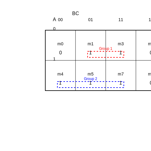
Karnaugh's motivation stemmed from a need to help simplify complicated logical designs and maximize efficiency via visual representation. His innovative approach represented minterms on a two-dimensional grid, where adjacent squares corresponded to terms differing by only one variable. This visual method allowed for easier grouping of 1s (true values) and 0s (false values), streamlining logical simplification and minimization efforts.
Development of Formal Techniques
As the field progressed throughout the 1950s and 1960s, Karnaugh maps became standard in the synthesis of digital circuits. The systematic approach enabled electrical engineers to optimize designs efficiently, significantly improving circuit efficiency—especially crucial during an era where component counts were high and space was limited.
From early applications in relay circuits to modern digital integrated circuits, the evolution of K-maps has mirrored advancements in technology. Thus, while they start as a method for manual simplification, *K-maps* are now incorporated into various simulation software and digital design tools, bridging the gap between manual techniques and automated processes.
Practical Applications
The practical relevance of Karnaugh maps extends beyond historical significance; they are implemented in various real-world applications, including:
- Digital circuit design and optimization
- Minimizing logic functions in integrated circuits and FPGAs
- Teaching fundamental concepts of Boolean algebra in academic environments
- Reducing the complexity of decision tables in design automation software
In conclusion, the history and development of Karnaugh maps illustrate a significant leap in the art and science of logical simplification. Their ongoing relevance in modern engineering applications continues to validate Karnaugh's original vision, supporting engineers and researchers in crafting more effective and efficient digital systems today.
1.2 Importance in Digital Circuit Design
Introduction to Karnaugh Maps
Karnaugh Maps (K-maps) serve as an invaluable tool in the realm of digital logic design, offering engineers and researchers a systematic method for minimizing Boolean functions without extensive mathematical computation. These maps facilitate visualization, aiding in recognizing patterns and relationships among variables, which can lead to significant reductions in logic circuit complexity.
Complexity Reduction
One of the principal advantages of deploying K-maps in digital circuit design is their effectiveness in reducing the complexity of Boolean expressions. A simplified Boolean expression translates directly into a less complex circuit design, which is crucial for several reasons:
- Cost-Effectiveness: A simpler circuit requires fewer components, thereby lowering material costs and enhancing reliability.
- Reduced Power Consumption: Fewer gates generally lead to lower power consumption, which is increasingly significant in battery-operated and portable devices.
- Increased Speed: Fewer gates in series can lead to faster signal propagation times, significantly boosting the performance of the circuit.
Real-World Applications
In practical applications, K-maps are frequently employed to design combinational circuits, such as adders, multiplexers, and encoders. For example, in the design of multiplexers that select among multiple input signals, K-maps can simplify the selection logic, ensuring that the operational speed and power efficiency are maintained. This is essential in systems where response time is critical, such as digital signal processors (DSPs) and real-time computing systems.
Case Study: Using K-maps in FPGA Designs
Field Programmable Gate Arrays (FPGAs) often benefit from the application of Karnaugh Maps. In a case study involving a digital frequency synthesizer, K-maps were utilized to optimize the logic necessary for phase detection and signal processing. The use of K-maps led to a more compact design, which fit within the constraints of the target FPGA architecture, demonstrating how efficient design solutions can lead to high-performing and resource-constrained digital systems.
Limitations and Considerations
Despite their numerous advantages, K-maps do have limitations. As the number of variables increases—specifically beyond five—the complexity of the map grows, making it less practical. Furthermore, for larger designs, automated tools often outperform manual simplification through K-maps due to the potential for human error in interpretation and grouping. It’s essential for engineers to strike a balance between manual methods and automated tools depending on the scale of the circuit.
Conclusion
The importance of Karnaugh Maps in digital circuit design lies not only in their ability to simplify complex Boolean functions but also in their practical benefits across several applications. As the field of digital electronics continues to advance, understanding and optimizing the use of K-maps remains a critical skill for engineers and researchers alike.
1.3 Basic Concepts and Terminology
Karnaugh Maps (K-Maps) serve as a vital tool in the simplification of Boolean expressions—an essential process in digital electronics design. Understanding the fundamental concepts and terminology associated with K-Maps enables engineers and researchers to optimize logic circuits more effectively. This detailed examination delves into essential concepts, facilitating a grasp of the K-Map methodology and its practical applications in circuit design.
Boolean Algebra and Logical Functions
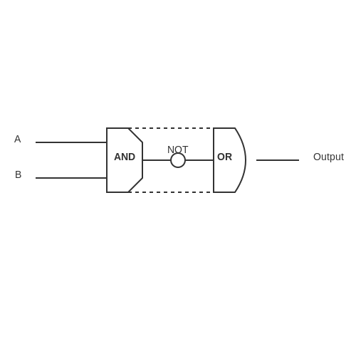
At the core of K-Maps lies Boolean algebra, a mathematical structure that captures the essence of digital logic. Boolean algebra operates on binary variables, typically represented with the values of 0 (false) and 1 (true). The key logical operations—AND, OR, and NOT—form the foundation of logical functions. In essence, a logical function maps combinations of binary inputs to a single binary output. These functions can be expressed using truth tables, which enumerate outputs for every possible combination of inputs, though this approach becomes cumbersome with increased variable count.
Karnaugh Maps Structure
A Karnaugh Map is a two-dimensional grid used to visually organize truth table data, simplifying the task of finding simplified expressions. Each grid cell corresponds to a different combination of input variables, while the arrangement of these cells reflects Gray code ordering, which changes only one variable at a time. This unique organization offers a valuable insight into relationships between variables, facilitating the identification of potential simplifications.
The general structure of a K-Map can be outlined as follows:
- Variables: K-Maps are typically designed for 2 to 6 variables, where the number of cells corresponds to 2n, with n being the number of variables.
- Cells: Each cell represents an output of the logical function defined by the relevant input combination.
- Grouping: Adjacent cells containing 1's are grouped together to simplify expressions using common variable factors.
Map Configuration and Grouping Strategies
Understanding how to configure and group K-Map cells is crucial for simplification. The following principles guide this process:
- Grouping Sizes: Groups can consist of 1, 2, 4, 8, or any power of 2 cells. Each group should be as large as possible while remaining rectangular.
- Overlap: Groups can overlap to allow for additional groupings, which can lead to further simplifications.
- Wraparound: The map can exhibit wraparound behavior, meaning cells on one edge are considered adjacent to those on the opposite edge.
Practical Applications
The application of K-Maps extends beyond theoretical exercises, finding real-world relevance in numerous fields:
- Digital Circuit Design: In designing combinational logic circuits, K-Maps assist engineers in minimizing gate counts, reducing costs, and enhancing circuit performance.
- Embedded Systems: K-Maps support the optimization of control logic in microcontroller applications, crucial for efficiency in resource-constrained environments.
- Signal Processing: In digital signal processing applications, K-Maps streamlining logical operations can lead to improved algorithm efficiency.
Thus, mastery of K-Maps equips professionals with robust tools for tackling complex digital logic design challenges, underscoring their critical role in modern engineering.
2. Representing Boolean Functions
2.1 Representing Boolean Functions
In the realm of digital electronics and computer science, the ability to manipulate and simplify Boolean functions is crucial. This subsection delves into the representation of Boolean functions through Karnaugh Maps (K-maps), a visual method that streamlines the process of minimizing logic expressions. Understanding these representations not only enhances computational efficiency but also provides a clearer insight into the logical flow of digital circuits.Understanding Boolean Functions
Boolean functions serve as the foundation for digital circuit design, expressing the relationship between binary variables. Each Boolean function can be represented in various forms, including truth tables, algebraic expressions, and graphical representations such as K-maps. The fundamental operations involved in Boolean functions are AND, OR, and NOT, which correspond to multiplication, addition, and negation in algebra, respectively. To illustrate this with a simple example, consider a Boolean function \( F(A, B, C) = A \cdot B + \overline{C} \). The variables \( A, B, \) and \( C \) can each take on the value of 0 or 1, leading to potential combinations that can be effectively organized using K-maps.Karnaugh Maps: A Visual Tool
Karnaugh Maps compile truth values derived from Boolean expressions into a two-dimensional grid, allowing for visual simplification. Each cell in a K-map corresponds to a minterm, representing a unique combination of the variables. For a function of three variables \( A, B, \) and \( C \), a K-map consists of 8 cells, organized in a specific order that reflects Gray code—the binary sequence where two successive values differ by only one bit. Consider a K-map for the function \( F(A, B, C) \):  The arrangement allows for an immediate visual assessment of adjacencies, which can be grouped to facilitate the simplification of the Boolean function.Constructing a Karnaugh Map
1. Determine the variables: Identify the number of variables in your Boolean function. 2. Set up the grid: Create a grid based on the number of variables, with 2^n cells (where n is the number of variables). 3. Fill in the K-map: Populate the K-map with 1s and 0s based on the truth table of the Boolean function you wish to simplify. 4. Group adjacent 1s: Form rectangles around groups of 1s, ensuring they are powers of two (1, 2, 4, 8, etc.). Each group corresponds to a simplified product term. 5. Derive the simplified expression: Translate the groups back into the simpler Boolean expression. As a practical application, this method is especially vital in the design of digital circuits such as multiplexers, demultiplexers, or finite state machines, where minimized forms translate to fewer gates and reduced manufacturing costs. By minimizing the complexity of Boolean functions through K-maps, engineers can enhance the performance and reliability of electronic systems. In summary, representing Boolean functions through Karnaugh maps provides a powerful tool for both analysis and design in digital systems. This method not only fosters a deeper understanding of Boolean algebra but also enables practical applications that resonate within the realm of modern computing and electronic engineering.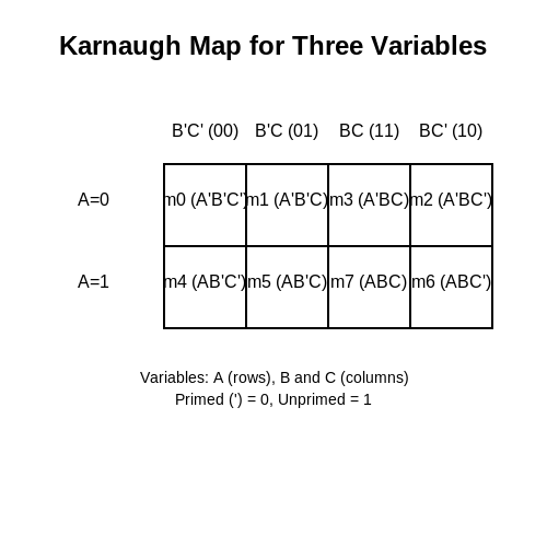
2.2 Setting Up the Grid
In the process of utilizing Karnaugh Maps (K-maps) for the simplification of Boolean expressions, the first crucial step is the precise configuration of the grid that represents the logical variables involved. This section aims to guide you through the setup of the K-map grid, ensuring you capture the necessary nuances pertinent to both theory and practical application.
Understanding the Layout of the Karnaugh Map
A K-map is essentially a two-dimensional representation of the truth table for a given logical function. The number of variables dictates the size of the K-map grid; specifically, a K-map for n variables features 2n cells. This layout allows for the straightforward visualization of adjacent cells that differ by only one variable, a key property in the simplification process.
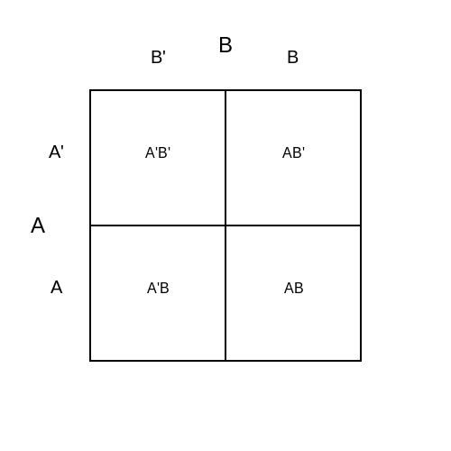
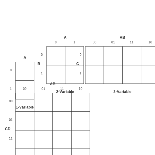
For example, a K-map for functions involving two variables consists of a grid with 22 = 4 cells arranged in a single row or a column, while a K-map for three variables comprises 23 = 8 cells, typically organized into two rows. The grid is structured as follows:
- The rows represent combinations of the first variable(s), while
- The columns denote combinations of subsequent variable(s).
Setting the Dimensions
To set up your K-map grid, begin by determining how many variables your Boolean expression includes:
- 1 Variable: A single cell (21)
- 2 Variables: 2 rows x 2 columns (22)
- 3 Variables: 2 rows x 4 columns (23)
- 4 Variables: 4 rows x 4 columns (24)
As you proceed to larger numbers of variables, the arrangement remains consistent: Maintaining adjacency properties becomes vital as you fill in the grid. For example, in a four-variable K-map, the layout resembles a square formatted grid, displaying all possible combinations of the variables while upholding Gray code, which ensures only one variable changes between adjacent cells.
Labeling the Rows and Columns
Each axis of the K-map grid must be labeled correctly to reflect the binary combinations they represent. The labels follow the Gray code pattern to preserve simplicity in adjacent comparisons:
- For 2 Variables: Label the rows as 00, 01, 11, and 10 for A and B
- For 3 Variables: Label rows as 000, 001, 011, 010, and columns as 00, 01, 11, 10 for A, B, and C
- For 4 Variables: Continue this labeling scheme across both dimensions, maintaining the Gray code sequence.
This process ensures that each cell can be indexed easily for further use in later operations, such as grouping 1s in the K-map for minimal expression development.
Practical Applications of K-map Grid Setup
The meticulous arrangement and labeling of the K-map grid have far-reaching implications in digital circuit design. In practice, engineers utilize K-maps to optimize logic circuits, leading to reduced hardware costs and enhanced performance. For instance, K-maps simplify the design of complex combinational logic circuits found in devices such as adders, multiplexers, and encoders, allowing for efficient design workflows in developing cutting-edge electronic systems.
In conclusion, the successful setup of a Karnaugh Map grid is paramount to its efficiency as a tool for simplifying Boolean functions. By mastering the grid setup, you prepare yourself for subsequent steps in logical minimization, which are essential in the fields of digital electronics and computer engineering.
2.3 Filling in the Karnaugh Map
The Karnaugh Map (K-map) is a critical tool in simplifying Boolean expressions and optimizing digital circuits. In this section, we will discuss the method of filling in the K-map, a vital skill for engineers engaged in combinatorial logic design, optimization, and minimization of logic functions. This technique is widely used not only in academic settings but also in industry practices, where efficiency and compactness in circuit design have a direct impact on performance and cost.
Understanding the Structure of a K-map
A K-map is a two-dimensional array that visually represents truth values (0 or 1) for various combinations of input variables. The arrangement of cells in a K-map is specifically designed based on Gray code ordering, which ensures that only one variable changes between adjacent cells. For instances with two variables, the K-map consists of four cells; for three variables, it contains eight cells; and for four variables, it can expand to sixteen cells. Each cell corresponds to a unique combination of variable states.
Step-by-Step Guide to Filling in the K-map
To fill in the K-map, follow these steps:
- Identify the Variables: Begin by identifying the number of variables in the Boolean function. This determines the size of the K-map.
- Create the K-map: Set up a K-map with the appropriate number of cells based on the number of variables. Each row and column corresponds to different combinations of variable states, leading to Gray code arrangement.
- Gather Truth Table Data: Construct a truth table for the desired Boolean function. This table will have a row for each potential combination of inputs and a corresponding output (1 or 0) indicating whether the function evaluates to true.
- Fill in the K-map: For each output of the truth table that is ‘1’, place a ‘1’ in the corresponding cell of the K-map. Conversely, populate the remaining cells with ‘0’. If using don’t-care conditions (often denoted as 'X'), include these properly based on the context.
- Verify the Filling: After completing the K-map, double-check the placement of ‘1’s to ensure it accurately reflects the truth table outputs.
Practical Example
Let us now illustrate the process by considering a function of three variables: \( A \), \( B \), and \( C \), with the following truth table:
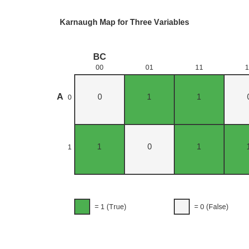
Based on this truth table, we fill out the K-map. For three variables, the K-map has eight cells. Fill each cell corresponding to the combinations listed to reflect the output states as shown.
Visual Representation:
For this specific function, after filling out the K-map, we would see a clear pattern where the cells filled with '1' help in identifying groups for simplification later.
The Importance of Grouping
Once the K-map is filled, the next crucial step involves grouping adjacent cells containing ‘1’s into rectangles. These groups, ideally containing 1, 2, 4, 8, and so forth, lead to simplified expressions that correspond to the original function. Each group represents a product term in the minimized Boolean expression, leading to more efficient circuit designs.
In conclusion, filling in a Karnaugh Map is not just about placing binary values into cells; it’s about understanding the relationships between variable states and honing the ability to simplify complex Boolean functions, a skill highly relevant in various fields such as electrical engineering, computer science, and systems design.
As you progress with K-maps, consider exploring tools and software that can handle extensive functions, as they often offer built-in K-map solvers that can assist in larger problems.
3. Identifying Groups
3.1 Identifying Groups
Karnaugh maps (K-maps) provide a visual method for simplifying boolean expressions and are widely used in digital circuit design. Once a K-map is constructed, the next crucial step is to identify groups within the map that will yield the simplest logical expression. Grouping involves identifying adjacent cells, or '1's, that can be combined to minimize the complexity of the logic function represented.
Understanding Grouping in K-maps
Grouping in K-maps follows specific rules that ensure the simplification process is both effective and efficient. The primary goal is to cover all the '1' entries in the map using the least number of groups, with each group adhering to certain criteria:
- Each group must contain 1, 2, 4, 8, etc. (powers of two) '1's. Grouping fewer or non-power-of-two cells disrupts the simplification process.
- Groups can wrap around. This means that the leftmost and rightmost columns, as well as the top and bottom rows, can be considered adjacent.
- Overlapping groups are permissible. Often, you may find that certain '1's are part of multiple groups, which can help achieve further simplification.
Types of Groups
Identifying groups can be approached in different ways, but common types include:
- Single '1' Groups: Used when a '1' cannot be combined with any adjacent cell.
- Pairs: Two adjacent '1's are grouped together to capitalize on their combined coverage.
- Quads: Four '1's are grouped in a rectangle, maximizing area usage.
- Octets: Eight '1's make the most comprehensive grouping, often leading to significant simplification.
Practical Example
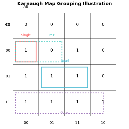
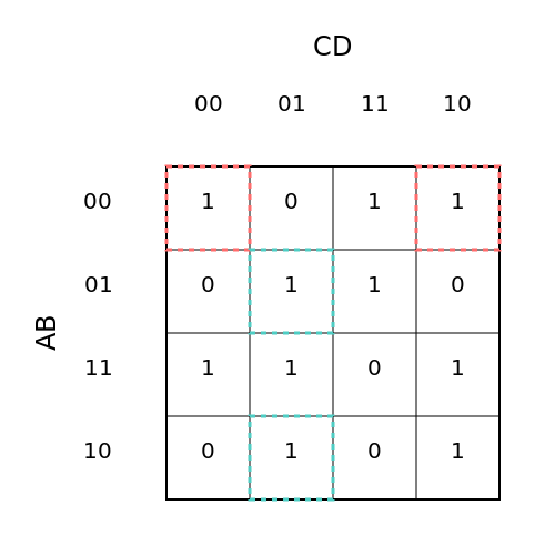
Consider a 4-variable K-map structured as follows:
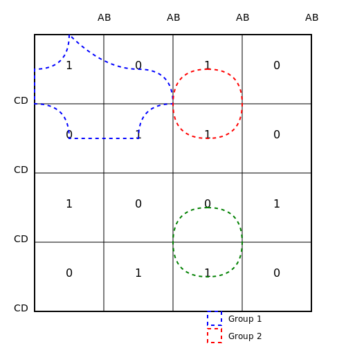
In the above K-map, we see a mix of '1's and '0's. You could identify a quad formed by (0,0) and (1,1) coordinates, as these positions can be covered while following the wrapping rule. Identifying and marking such groups simplifies the resulting boolean expression.
Real-World Applications
The capability to simplify boolean expressions through K-maps has significant implications in practical engineering applications, particularly in:
- DIP Design: Streamlining designs in Digital Integrated Circuits (DIPs) enhances efficiency and reduces silicon area.
- FPGA Development: Designers utilize K-maps to optimize logical functions and resource allocation in Field Programmable Gate Arrays (FPGAs).
- Embedded Systems: Simplified logic leads to enhanced performance in control systems, where every reduction counts.
As we move forward in this tutorial, the next section will explore how these identified groups translate into simplified boolean equations and practical circuit implementations.
3.2 Rules for Grouping
In the context of Karnaugh maps (K-maps), the correct application of grouping rules is essential for simplifying Boolean expressions effectively. With advanced applications ranging from digital circuit design to optimization in various computational fields, understanding these rules allows engineers and researchers to derive minimal forms that lead to reduced circuit complexity and improved performance.Understanding Grouping in K-Maps
Grouping in Karnaugh maps involves identifying adjacent cells that correspond to '1's (true values) in the Z-values of a truth table. The objective is to form the largest possible rectangular groups of these '1's, adhering to specific rules that not only streamline the simplification process but also enhance the overall efficiency of the resulting circuit.Key Rules for Grouping
The fundamental rules for effective grouping within K-maps are as follows:- Rectangular Groups: Groups can only be formed in rectangular shapes, which can be squares of sizes 1x1, 1x2, 2x1, 2x2, etc. The sizes must be powers of two (1, 2, 4, 8, etc.).
- Adjacency: A '1' can be grouped with another '1' if they are adjacent, horizontally or vertically. Diagonal adjacency does not count.
- Wrapping Around: K-maps allow wrapping, meaning that the edges of the grid are connected. A cell on one edge can group with a cell on the opposite edge across the K-map.
- Overlapping Groups: It is permissible to overlap groups to maximize the number of groups formed, especially when dealing with larger K-maps where smaller groups may result in different minimized expressions.
- Minimize Groups: Always aim for the largest possible group of '1's first, as larger groups yield simpler expressions. Smaller groups can act as a backup if no larger groups are available.
Practical Application of Grouping Rules
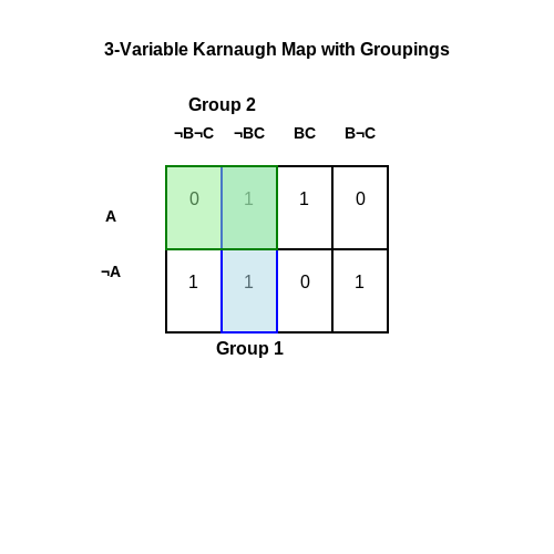
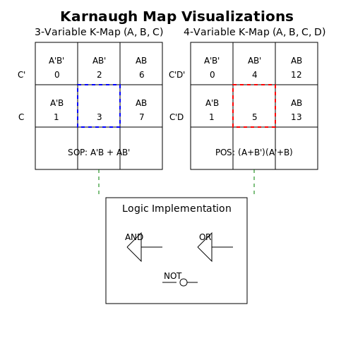
When simplifying Boolean expressions, the implications of these grouping rules can be observed in real-world applications such as digital circuit design. For instance, when creating combinational circuits like multiplexers or decoders, leveraging the grouping rules can lead to simpler logic designs, which are easier to implement and consume less power. To visualize the grouping process, consider a K-map for three variables:Diagram of a 3-variable K-map showing possible groupings.
3.3 Forms of Simplified Expressions
In the realm of digital design, Karnaugh maps (K-maps) stand as an essential tool for simplifying Boolean expressions. This process not only aids in minimizing the complexity of digital circuits but also enhances performance and reduces cost. A thorough understanding of the various forms of simplified expressions derived from K-maps can significantly impact the efficiency of hardware implementation.Understanding Boolean Simplification
Boolean algebra provides a structured framework for manipulating logical expressions. Each expression can be represented by hardware components, with the aim being to minimize the number of components through simplification. Simplified expressions yield a circuit that consumes less power, occupies less space, and operates with enhanced speed. The fundamental goal here is to achieve the simplest form of the original Boolean expression while maintaining equivalence in logical outputs. The process begins with the construction of a K-map for a given Boolean function. Each cell in the K-map corresponds to a minterm of the function, representing combinations of variable states that yield a true (1) output. By clustering adjacent cells that contain 1s (true outputs), we can derive simplified product terms, which can then be combined into a final Boolean expression.Forms of Simplified Expressions
There are several forms that simplified Boolean expressions can take, particularly when deriving from K-maps: 1. Sum of Products (SOP): This is perhaps the most common form, where the final expression consists of a sum (logical OR) of products (logical AND) of literals. In this form: - Each product term corresponds to a set of minterms on the K-map. - The SOP format is preferred for its clarity and straightforward implementation in digital circuits. For example, a simplified SOP expression for a function might be represented as: $$ F(A, B, C) = A'B + AC + BC' $$ Here, `A`, `B`, and `C` are Boolean variables, and the prime denotes logical NOT. 2. Product of Sums (POS): Alternate to SOP, the POS consists of a product of sum terms. Each sum term corresponds to a maxterm from the K-map: - This form emphasizes covering the minterms that result in a false (0) output. For example, a simplified POS expression might be expressed as: $$ F(A, B, C) = (A + B')(A' + C) $$ The advantageous aspect of the POS is seen in certain applications requiring logical disjunction to form more complex functions. 3. Canonical Forms: Both SOP and POS can be expressed in canonical forms, where every variable is represented explicitly. In the canonical SOP form, all possible minterms are summed, while the POS requires all maxterms to be multiplied. Although these forms can lead to larger expressions, they provide a standardized way to represent Boolean functions. 4. Mixed Forms: Occasionally, a blend of SOP and POS can yield a more practical expression based on specific circuit requirements. The designer's familiarity with the circuit's behavior often informs the choice of expression format, leveraging advantages of both representations.Practical Relevance and Applications
The effective simplification of Boolean expressions using K-maps finds direct applications across various fields, particularly in digital electronics: - Integrated Circuits Design: Minimizing gate counts directly influences the die size and manufacturing complexity. - Control Systems: Optimized logical arrangements can lead to faster response times and reduced latency in digital controllers. - Versatile Display Systems: Applications in embedded systems benefit from enhanced logic simplification, improving performance in computational devices. Ultimately, understanding the various forms of simplified expressions allows for informed decisions when designing complex digital systems, ensuring that performance does not come at the expense of increased cost or complexity. By clearly delineating the forms of simplified expressions, engineers and researchers can leverage K-maps to achieve optimized and practical implementations of digital logic. Through practice and exploration of these forms, engineers can hone their skills in digital circuit design, ultimately leading to more efficient systems.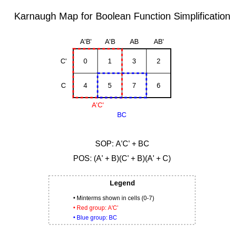
4. Multi-variable Expressions
4.1 Multi-variable Expressions
The analysis and simplification of multi-variable Boolean expressions are critical in fields such as digital electronics and computer engineering. These expressions can represent complex digital circuits, where the need for efficient design and minimal resource use becomes imperative. Karnaugh maps (K-maps) serve as a visual tool to simplify Boolean expressions involving two to five variables, facilitating easier recognition of patterns that govern these expressions.Understanding Multi-variable Expressions
A multi-variable Boolean expression is constructed from logical variables that may take binary values (0 or 1). In digital logic, each variable can represent a switch or input signal, leading to various combinations of outputs. This complexity increases with the number of variables involved. For instance, an expression involving three variables (A, B, and C) generates \(2^3 = 8\) possible combinations of inputs. To approach the simplification of such expressions effectively, K-maps offer a systematic way to minimize logic functions visually. By minimizing a multi-variable function, engineers can reduce the number of logic gates needed in a circuit, directly impacting the circuit’s cost, power consumption, and size.Constructing a Karnaugh Map
The construction of a K-map begins by defining the number of variables. For a three-variable Boolean function, the K-map consists of 8 cells arranged in a grid format, each representing one of the possible input combinations. The next step involves filling in the cells based on the output values of the function. For example, consider the function \(F(A, B, C) = \Sigma (1, 2, 5, 6)\). Here, the notation \(\Sigma\) denotes the summation of minterms corresponding to specific combinations: 1. Minterm 1 corresponds to \(A'B'C\) 2. Minterm 2 corresponds to \(A'BC'\) 3. Minterm 5 corresponds to \(AB'C\) 4. Minterm 6 corresponds to \(ABC'\) Upon filling the K-map, adjacency becomes paramount. Cells can be combined based on their values. Adjacent cells, which can be horizontally or vertically connected, represent Boolean expressions that can be grouped together to simplify the expression further.Example of Using a K-map for Three Variables
We shall visualize an example K-map for three variables (A, B, C) concerning our function \(F\). To depict the filling of the K-map for minterms 1, 2, 5, and 6, we denote '1' for each corresponding cell and '0' elsewhere, configured as follows:| BC | 00 | 01 | 11 | 10 |
|---|---|---|---|---|
| A=0 | 0 | 1 | 0 | 1 |
| A=1 | 0 | 1 | 1 | 0 |
Simplifying the Expression
The next stage is to extract simplified Boolean expressions from the arranged groups. For our K-map: - Group formed by cells (1, 2): This group corresponds to \(A'B\) - Group formed by cells (2, 6): This corresponds to \(BC'\) Through these combinations, the minimized expression can be concluded as: $$ F(A, B, C) = A'B + BC' $$ Each variable’s simplified representation harnesses the power of K-maps to simplify logic circuitry effectively. The practical implication of this simplification process is invaluable in optimizing modern electronic systems, where space, power efficiency, and speed are critical.Conclusion
The capacity to manage and simplify multi-variable expressions using Karnaugh maps stands as a fundamental skill for engineers and students immersed in digital electronics. By transforming complex expressions into optimized circuits, K-maps facilitate the advancement of technology in systems ranging from microcontrollers to sophisticated computing architectures. This section establishes a foundational understanding of the K-map's significance in handling multi-variable expressions, paving the way for even more complex designs and applications in subsequent sections.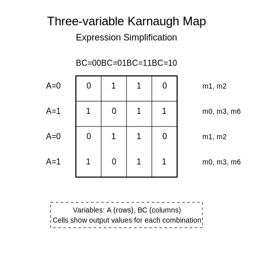
4.2 Practical Circuit Design Examples
Karnaugh maps, often abbreviated as K-maps, are a powerful tool for simplifying Boolean algebra expressions, which is crucial in the design of digital circuits. In this section, we will delve into specific examples of circuit designs where K-maps play a pivotal role. We will explore how these maps can be utilized to minimize the complexity of logic circuits, thus enhancing performance and reducing costs.
Understanding Circuit Design through Karnaugh Maps
As we progress into practical applications, it’s essential to grasp how K-maps can be utilized to design combinational circuits. A combinational circuit is a type of electronic circuit in which the output is solely determined by the present input conditions. The K-map offers a visual method to simplify Boolean expressions that describe these input-output relationships.
Consider a simple case of designing a circuit for a function with three variables, A, B, and C. The truth table for such a circuit might define the output as true (1) for various combinations of inputs. Using K-maps, we can efficiently determine the most simplified Boolean expression for the circuit, which directly impacts the circuit's logic gate implementation.
Example Circuit: Full Adder Design
A common application of K-maps in circuit design is the implementation of a full adder. A full adder takes three inputs—two significant bits, A and B, and a carry-in bit, Cin—and outputs a sum bit and a carry-out bit. The truth table for a full adder can be represented as follows:
| A | B | Cin | Sum (S) | Carry-out (Cout) |
|---|---|---|---|---|
| 0 | 0 | 0 | 0 | 0 |
| 0 | 0 | 1 | 1 | 0 |
| 0 | 1 | 0 | 1 | 0 |
| 0 | 1 | 1 | 0 | 1 |
| 1 | 0 | 0 | 1 | 0 |
| 1 | 0 | 1 | 0 | 1 |
| 1 | 1 | 0 | 0 | 1 |
| 1 | 1 | 1 | 1 | 1 |
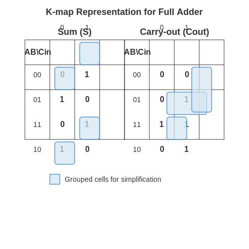
Now, let's derive the K-map for this full adder. The critical output functions, Sum and Carry-out, can be plotted onto a 3-variable K-map which will help us find the minimal expressions.
K-Map Representation
For the Sum function (S), the K-map looks like this:
The minimal expression for the Sum is derived from the grouped ones in the K-map, resulting in:
Next, for the Carry-out function (Cout), the corresponding K-map configuration reveals:
The minimal expression for the Carry-out can then be expressed as:
Implementation in Real Circuits
Using these minimized expressions, we can implement the full adder using basic logic gates such as AND, OR, and XOR. The benefit of utilizing Karnaugh maps is clearly seen in the resulting circuit; fewer gates lead to lower power consumption, increased speed, and reduced physical space on the circuit board.
Instances of K-map applications are ubiquitous in digital electronics, extending to complex systems like multiplexers and demultiplexers, where the simplification of multiple inputs is crucial. The ability to derive minimal expressions directly from a truth table or logic circuit via K-maps makes them an invaluable tool in the design interplay between theoretical concepts and physical implementations.
As we transition to multifaceted examples in the subsequent sections, the practices of K-map utilization will continue to serve as a foundational pillar in the landscape of digital electronics.
4.3 Limitations and Considerations
Understanding the practical implications of Karnaugh Maps (K-maps) is essential for effective digital circuit design. While K-maps present a powerful tool for simplifying Boolean expressions, they are not without their limitations, which can affect the scope of their application in real-world scenarios.Complexity in Larger Systems
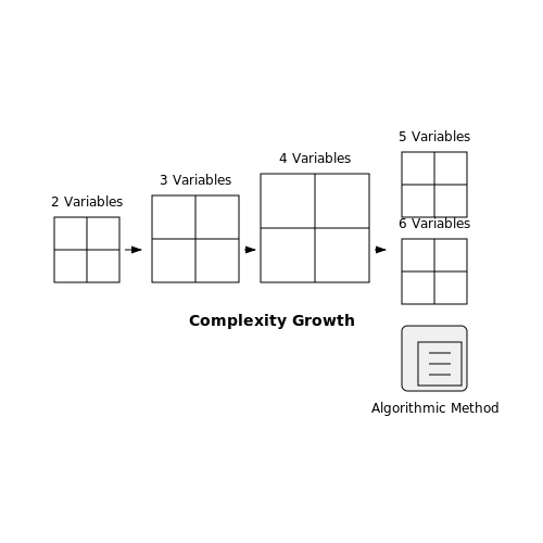
Karnaugh Maps are particularly effective for simplifications involving up to six variables. Beyond this, the maps become increasingly complex and unwieldy. The primary challenge arises from managing the significant number of combinations that need to be evaluated. As the variable count increases, the grid grows exponentially, leading to difficulties in visualization and manipulation. In practice, most engineers prefer algorithmic methods, such as Quine-McCluskey, for larger Boolean functions, as these can systematically handle any number of variables. This shift to computational approaches may also assist in minimizing potential errors that could arise when using K-maps for high-variable systems.Human Error and Misinterpretation
Another crucial consideration is the inherent potential for human error. The manual process involved in constructing and interpreting K-maps is prone to mistakes, particularly in complex configurations. The misplacement of cells or incorrect grouping can result in erroneous simplifications. Moreover, while K-maps help derive minimal forms, they do not provide a unique solution. Multiple equivalent expressions can emerge from the same K-map. Recognizing and distinguishing one from another requires a deep understanding of both the theory and the practical implications of the derived Boolean expressions.Limited Applicability to Certain Logic Functions
There are specific classes of logic functions where K-maps may not provide the most effective simplification. Functions characterized by high levels of redundancies may be poorly represented in K-map form. For example, a highly irregular function might not highlight clear groupings or patterns, thereby rendering the simplification process less intuitive. In real-world applications, engineers often encounter these irregular functions in digital design implementations. Hence, relying solely on K-maps could lead to inefficient or cumbersome solutions. Digital circuit designers must recognize when to leverage K-maps and when to transition to alternative methodologies better suited for complex logic operations.Spatial Limitations
In practice, K-maps are visual tools. Their effectiveness is partly derived from their graphical representation. However, this spatial dependency can also be limiting, particularly in two-dimensional maps. The dimensions of the map constrain the maximum number of variables; as a result, extending to higher dimensions becomes impractical. Moreover, translating a K-map into physical circuits can ellude the simplicity that K-maps purport. In implementation, the layout of the circuits might introduce latency, parasitic effects, and signal degradation that are not addressed by the K-map's theoretical construct.Practical Strategies for Effective Use of K-maps
To mitigate these limitations while still reaping the benefits of K-maps, engineers can adopt several strategies:- Utilize software tools capable of handling complex Boolean expressions to circumvent higher-variable challenges.
- Maintain a systematic documentation process during manual entry and interpretation, minimizing the risk of error.
- Learn to identify functions that yield better results with alternative simplification methods.
- Incorporate simulation tools to test circuit designs derived from K-map outputs before final deployment.
5. Karnaugh Maps with Don't Cares
5.1 Karnaugh Maps with Don't Cares
Karnaugh maps (K-maps) provide an efficient way to simplify Boolean expressions and derive optimized digital logic circuit designs. In practical applications, it is common to encounter scenarios where certain input conditions do not affect output behavior, termed as don't care conditions. These conditions arise in various contexts, including undefined outputs during certain states in sequential circuits, thus offering flexibility in design optimizations.
Considering don't care conditions can significantly impact the simplification process, enabling more compact expressions and less complex circuit layouts. This subsection delves into the methodologies for incorporating don't care conditions into Karnaugh maps, enhancing the map's utility in practical scenarios.
Understanding Don't Care Conditions
A don't care condition occurs when the output of a circuit is not defined for specific input combinations. These can be strategically utilized when minimizing Boolean expressions. By treating these inputs as either 0 or 1, engineers can contribute to achieving a more optimized design. For example, if a certain input combination does not arise in practice, it may simplify the logic functions without affecting the overall operation.
How to Identify Don't Care Conditions
Don't care conditions are generally identified through simulation, design specifications, or empirical testing. As designers, we can recognize these inputs by analyzing performance under various operational constraints. Once identified, these conditions can be marked in the Karnaugh map with a symbol, typically "X," indicating that the values can be used flexibly depending on the necessity of optimization.
Implementing Don't Care Conditions in Karnaugh Maps
Integrating don't care conditions into a Karnaugh map follows a structured method. Below, the steps illustrate how to effectively use don't care states in a K-map:
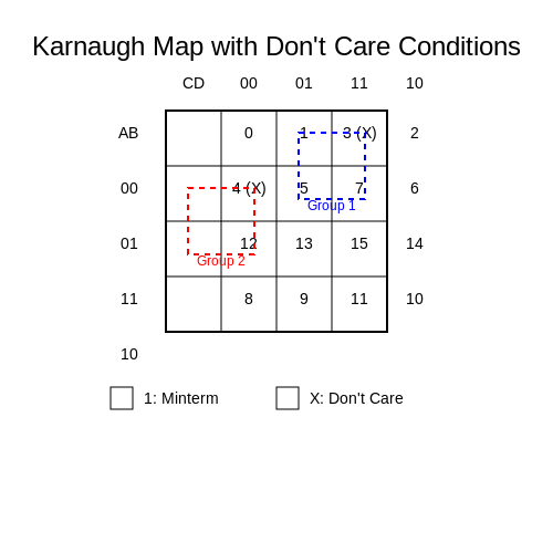
- Step 1: Initialize the K-map for your Boolean function by plotting the required minterms for which the function is true (output = 1).
- Step 2: Identify and plot the don't care conditions on the K-map by placing "X" in the relevant cells.
- Step 3: Combine the minterms and don't care conditions to form larger groups on the Karnaugh map. Each grouping can include cells represented by either 1s or Xs.
- Step 4: Use the largest possible groups to minimize the expression, allowing for greater flexibility in utilizing the "X" cells as either 1 or 0.
As an example, consider a K-map with four variables where specific conditions are defined as don't cares. Let’s assume minterms 1, 2, and 5 are 1, while terms 3 and 4 are don't cares. After plotting these on the K-map, the optimal grouping might yield a simplified Boolean expression that is less complex than if don't cares were ignored.
Real-World Applications
The practical significance of applying don't care conditions in Karnaugh maps is vast. In digital design, such methods are employed in fields ranging from microprocessor design to digital signal processing. For example, a designer creating a microcontroller may utilize don't cares to minimize gate counts, thus reducing power consumption.
Moreover, automating Karnaugh map simplifications in software tools allows engineers to quickly analyze and incorporate don't care conditions, streamlining the design and verification processes. This integration of advanced methodologies not only enhances efficiency but also enables designers to innovate within constrained parameters of performance and resource utilization.
In conclusion, the strategic application of don't care conditions within Karnaugh maps not only simplifies Boolean expressions but also substantially impacts the physical implementation of digital circuits, making it a vital concept in the field of electronic design.
5.2 Using Karnaugh Maps for Memory Optimization
In the realm of digital design, memory optimization is a pivotal concern, especially in resource-constrained environments like embedded systems or intricate integrated circuits. Through the application of Karnaugh maps, engineers can achieve significant reductions in both logical complexity and memory usage, thus enhancing performance and efficiency.Understanding the Basics of Memory Optimization
Before delving into the specific applications of Karnaugh maps for memory optimization, it’s essential to grasp the core principles of memory usage in digital systems. Memory in digital electronics often refers to storage elements in a circuit which can include flip-flops, registers, or RAM modules. Optimizing memory fundamentally aims to reduce the number of used storage elements while maintaining or improving system functionality. When discussing memory optimization, reducing state variables is a key factor. By minimizing the number of states needed to represent a truth table, we can effectively reduce the circuit size, power consumption, and ultimately costs.Karnaugh Maps: A Recap
Karnaugh maps are graphic representations used to simplify Boolean algebra expressions. Each cell in a K-map corresponds to a minterm of a truth table, and adjacent cells differ by a single bit, following the Gray code order. The primary objective of using K-maps is to visualize relationships and facilitate the identification of common factors, resulting in more effective simplifications. When you group adjacent cells containing 1s in a Karnaugh map, the outcome reveals simplified Boolean expressions, which can translate directly into electronic circuits. The fewer the logical gates required to implement a specific function, the less memory and power are utilized.The Process of Memory Optimization Using Karnaugh Maps
To employ Karnaugh maps for memory optimization, follow this structured approach: 1. Define the Problem: Start with a clear understanding of the function you wish to implement. Compile the truth table that illustrates the desired output based on input states. 2. Construct the Karnaugh Map: Create a K-map corresponding to the number of variables in your function. Each cell of the K-map will represent a one-to-one mapping of input combinations to output values as indicated in the truth table. 3. Group the Ones: Identify groups of 1s in the K-map. Each group must contain 1, 2, 4, 8, (or powers of 2) and should be as large as possible. Groups can wrap around to leverage the K-map’s adjacency. 4. Derive Simplified Expressions: With the groups defined, extract simplified Boolean expressions representing the logic of your circuit. Aim to cover all 1s with the minimum number of groups possible. 5. Implementation of the Circuit: Translate the simplified expression back into a hardware implementation utilizing the minimal number of gates and flip-flops required. This directly translates into reduced memory usage by using less storage hardware.Case Study: Traffic Light Control System
Consider a simplified example involving a traffic light control system with three states (Red, Yellow, Green) represented by three separate inputs. The aim here is to minimize the memory required for the state machine that governs the light changes. - The simplified truth table is constructed, showing the relations between input and output. - The K-map is generated and grouped accordingly. Depending on state transitions, it’s likely that many of these states can share outputs or transition conditions, effectively reducing the state representation needed. - By applying Karnaugh map techniques, the necessary logic can result in a circuit composed of fewer elements, thereby minimizing memory consumption. This real-world application illustrates not only the practicality of Karnaugh maps in developing efficient systems but also how these techniques can be generalized to various fields, including traffic systems, digital calculators, and more complex state machine designs.The Benefits of Using Karnaugh Maps for Memory Optimization
Utilizing Karnaugh maps provides numerous advantages: Efficiency in Design: By minimizing the number of necessary logic gates, systems can achieve lower power consumption and cost. Enhanced Performance: With a simplified circuit, execution times can improve due to a minimized propagation delay. Scalability: Simplified circuits can easily scale to larger systems with enhanced modularity, preserving efficiency as complexity increases. In summary, when applied skillfully, Karnaugh maps serve as essential tools in the arsenal of any engineer, particularly when focused on memory optimization. By leveraging their graphical capabilities for circuit simplification, innovative solutions emerge, driving both efficiency and effectiveness in design.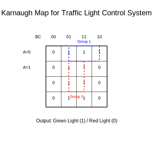
5.3 Computer Aided Simplification Techniques
In recent years, the field of digital logic design has benefited significantly from computer-aided design (CAD) tools that simplify Boolean expressions and optimize combinatorial circuits. The utilization of computer-aided simplification techniques is not only effective for reducing the complexity of logic designs but also essential for implementing robust and efficient systems in practical applications, such as microprocessors and digital signal processors.The Role of CAD Tools in Simplification
Traditionally, engineers relied on manual techniques, such as Karnaugh maps and Boolean algebra, to simplify logic expressions. However, as designs grew more complex, these methods proved time-consuming and prone to human error. Computer-aided design tools have emerged as vital solutions that automate simplification processes, enabling a rapid evaluation of numerous simplification paths. Many modern CAD tools employ algorithms based on:- Quine-McCluskey algorithm: A tabular method that systematically derives the minimum expression through iteration.
- Binary Decision Diagrams (BDDs): A data structure that encodes Boolean functions, facilitating efficient manipulation and simplification.
- Logic Simulation: Utilizing simulation to verify the functionality of the simplified logic against specifications.
Quine-McCluskey Algorithm in Depth
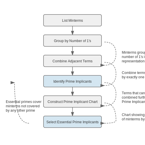
The Quine-McCluskey algorithm offers a systematic method to minimize Boolean functions. It works in two principal phases: 1. Prime Implicants Generation: - The procedure begins by listing the minterms of the Boolean function and constructing a table, grouping terms based on the number of ones in their binary representation. - Terms that differ by one bit are combined, forming new products until no further combinations are possible. 2. Prime Implicant Chart and Selection: - The next step involves creating a prime implicant chart where rows represent prime implicants and columns represent minterms. - Utilizing techniques like Petrick's method, one can determine the essential prime implicants that form a minimal expression. While the Quine-McCluskey algorithm guarantees finding a minimal form, it may become computationally intensive for a significant number of variables and terms.Binary Decision Diagrams (BDDs) as Efficient Alternatives
Another powerful tool in Boolean function simplification is the Binary Decision Diagram (BDD). BDDs efficiently represent Boolean functions through a directed acyclic graph structure. The notable advantages of BDDs include: - Reduced Memory Usage: By sharing common substructures within the graph, BDDs can represent complex functions compactly. - Quick Evaluation: The structured nature allows for rapid evaluation of functions through variable assignments. - Robust Simplification: BDDs can facilitate easy extraction of essential prime implicants, akin to the earlier mentioned methods. However, the efficiency and size of the BDD can heavily depend on the variable ordering, making the selection of an optimal order critical in practice.Real-World Applications
The strategic application of computer-aided simplification techniques is invaluable in several modern electronics areas: - Microcontroller Design: By optimizing logical expressions, designers can minimize the number of gates required, leading to smaller, more power-efficient chips. - FPGAs: Field Programmable Gate Arrays benefit from efficient logic synthesis aiding in faster reconfiguration and task execution. - Embedded Systems: The rapid iteration of logic designs through CAD tools accelerates the development cycle of embedded applications, enhancing responsiveness to market changes. Integrating such CAD techniques can significantly enhance the reliability and efficiency of digital systems while meeting practical performance expectations.Understanding the workings and applications of these advanced simplification techniques can position engineers and researchers at the forefront of digital design innovation.
6. Example Problems
6.1 Example Problems
In this subsection, we will delve into practical applications of Karnaugh Maps (K-maps) through a series of example problems that illustrate their utility in simplifying Boolean expressions and optimally designing digital logic circuits.Understanding the K-map Framework
Karnaugh Maps serve as a convenient tool for visualizing the minimization of Boolean expressions, particularly when dealing with two to four variable scenarios. For a given Boolean function, K-maps can simplify the process by grouping ones that are adjacent in the map. Each group corresponds to a term in the simplified Boolean expression. To illustrate the process, we will tackle several problems that progressively showcase how K-maps can be applied effectively.Example Problem 1: Simplifying a Two-Variable Expression
Consider the Boolean function defined by the truth table as follows: | A | B | F(A,B) | |---|---|-------| | 0 | 0 | 0 | | 0 | 1 | 1 | | 1 | 0 | 1 | | 1 | 1 | 0 | From this truth table, we can see that the output is true for the minterms 1 and 2 (expressed as \(A'B\) and \(AB'\) respectively). To construct the K-map: 1. Organize the variables along the axes. For two variables (A and B), we will label the rows and columns accordingly. 2. Fill in the K-map based on the truth table: B 0 1 +-------+ A | 0 1 | | | 0 | 0 1 | +-------+ 1 | 1 0 | | | +-------+ With ones in the appropriate positions, we can see there are two adjacent cells in the K-map that correspond to a grouping of \(AB'\) and \(A'B\): The simplified Boolean expression can be represented as: $$ F(A, B) = A'B + AB' $$Example Problem 2: Simplifying a Three-Variable Expression
Now, let's explore a more complex scenario involving three variables: A, B, and C. Consider the function defined by the truth table below: | A | B | C | F(A,B,C) | |---|---|---|-------| | 0 | 0 | 0 | 0 | | 0 | 0 | 1 | 1 | | 0 | 1 | 0 | 1 | | 0 | 1 | 1 | 1 | | 1 | 0 | 0 | 0 | | 1 | 0 | 1 | 1 | | 1 | 1 | 0 | 1 | | 1 | 1 | 1 | 0 | The relevant minterms here are 1, 2, 3, 5, and 6. Creating the K-map for this function involves a bit more complexity: 1. Construct the K-map: BC 00 01 11 10 +----------------+ A | 0 | 1 | 1 | 0 | | | | | | 0 | 0 | 1 | 1 | 1 | +----------------+ 1 | 0 | 1 | 0 | 1 | | | | | | +----------------+ 2. Identify groups: - Grouping the ones gives us two groups that combine terms: - Group 1 from cells (0,1) and (0, 2); results in \(A'C\). - Group 2 from cells (1,1) and (1, 2); simplifies to \(AB'\). Thus, the finalized Boolean expression simplifies to: $$ F(A, B, C) = A'C + AB' $$Example Problem 3: A Four-Variable Scenario
For our final example problem, let’s consider a four-variable function defined by its truth table. The minterms for the function \(F(A,B,C,D)\) are defined as: 1, 5, 6, 7, 9, 13, 14. Proceed similarly with this four-variable function: 1. Construct the 4-variable K-map: CD 00 01 11 10 +----------------+ AB | 0 | 1 | 1 | 0 | | | | | | 00 | 0 | 1 | 1 | 0 | +----------------+ 01 | 0 | 0 | 1 | 1 | | | | | | +----------------+ 2. Identify groups: - Major groups yield terms that significantly reduce complexity, for instance: - One group could yield \(C'D'\) followed by interactions leading to more combinations. By systematically analyzing groups that cover the K-map, we arrive at a minimized expression: $$ F(A, B, C, D) = B'C + A'D' $$Conclusion
These example problems showcase the versatility and efficacy of Karnaugh Maps in minimizing Boolean expressions across different variables. They highlight both the mathematical framework behind K-maps and their profound implications in digital logic design, where optimized expressions translate into more efficient circuit implementations. For advanced applications, consider expanding this knowledge to larger numbers of variables or utilizing software tools for automatic minimization when dealing with high-order functions. The ability to simplify logic circuits effectively has a profound impact on reducing chip size and power consumption in integrated circuits.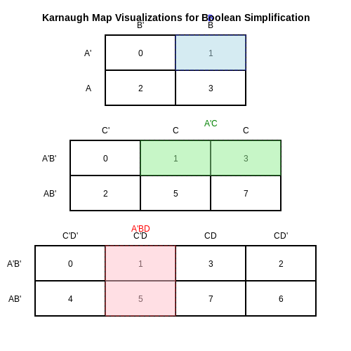
6.2 Challenge Problems
As we delve into the practical applications of Karnaugh Maps, it is crucial to reinforce our understanding through problem-solving challenges. These difficulties not only test theoretical knowledge but also enhance our skills in simplifying logical expressions and recognizing patterns through visual representation. Below, you will find various challenge problems designed to deepen your grasp of Karnaugh Maps.
Problem 1: Simplifying a Four-Variable Function
Consider the four-variable boolean function defined by the minterms {1, 3, 7, 11, 15}. Construct a Karnaugh Map to find the simplest boolean expression for this function. Once the K-Map is filled, group the ones into the largest possible rectangles. Based on your groups, derive the minimized expression.
After filling the K-Map, identify overlapping groups and calculate the minimized function. The anticipated outcome should enable you to compare the original and minimized expressions effectively.
Problem 2: Converting to SOP and POS Forms
Suppose you are given the truth table below, which describes a boolean function:
- A = 0, B = 0, C = 0, F = 0
- A = 0, B = 0, C = 1, F = 1
- A = 0, B = 1, C = 0, F = 1
- A = 0, B = 1, C = 1, F = 0
- A = 1, B = 0, C = 0, F = 0
- A = 1, B = 0, C = 1, F = 1
- A = 1, B = 1, C = 0, F = 1
- A = 1, B = 1, C = 1, F = 1
Your task is to create the Karnaugh Map for this function and generate both the Sum of Products (SOP) and Product of Sums (POS) expressions. Analyze the differences in complexity between the two forms.
Problem 3: Real-World Application Scenario
Imagine you are tasked with designing a simple digital circuit which will control an LED based on three sensor inputs (A, B, C). The LED should turn on when the conditions specified by the boolean function:
Use a Karnaugh Map to reduce this function, and then implement the minimized version using basic logic gates (AND, OR, NOT). Draw the circuit diagram representing your solution.
Problem 4: Deducing Missing Minterms
A hypothetical digital logic circuit outputs a truth table summarizing its function by the two minterms {0, 1, 2, 3, 4, 6}. Fill in the Karnaugh map and identify any missing minterms. Describe how the additions would impact the overall functionality of the circuit design.
In this set of challenge problems, you are encouraged to think critically about both the theoretical elements of Karnaugh Maps and their practical implications in electronics and logic design. Solutions should be verified independently or discussed with peers to foster a collaborative learning environment.
6.3 Solutions and Explanations
The application of Karnaugh maps (K-maps) in simplifying Boolean expressions is a critical skill in digital design, directly impacting the efficiency of logic circuits. This section explores various strategies for solving K-map problems, enriching your comprehension and showcasing practical examples of their applicability.
Understanding the Basics
A Karnaugh map organizes truth values of Boolean functions visually, facilitating the minimization of expressions through grouping. Each cell in the K-map represents a particular combination of input variables, which is mapped according to the Gray code sequence to ensure that only one bit changes between adjacent cells. This arrangement simplifies the identification of patterns—groups of 1s—that correspond to simplified product terms in the Boolean expression.
Solving K-map Problems Step-by-Step
Let's delve into a systematic approach to solving typical K-map problems, centered around a 4-variable K-map for the Boolean function:
To represent this function in K-map form, the first step is to populate the K-map grid based on the minterms (1s) provided:
- Minterm 0: 0000
- Minterm 1: 0001
- Minterm 2: 0010
- Minterm 5: 0101
- Minterm 6: 0110
- Minterm 7: 0111
- Minterm 8: 1000
- Minterm 9: 1001
- Minterm 10: 1010
- Minterm 14: 1110
Grid Construction and Grouping
A 4-variable K-map consists of a 4x4 grid. The rows and columns are designated as follows:
- Rows: AB = 00, 01, 11, 10
- Columns: CD = 00, 01, 11, 10
Next, we populate the K-map with 1s and 0s according to the specified minterms:
For instance, the populated K-map will look something like this:
| CD | 00 | 01 | 11 | 10 |
|---|---|---|---|---|
| 00 | 1 | 1 | 0 | 0 |
| 01 | 0 | 1 | 1 | 1 |
| 11 | 0 | 0 | 1 | 0 |
| 10 | 1 | 1 | 0 | 0 |
By visually inspecting the grid, the next step is to group the adjacent cells containing 1s. Groups can be formed with sizes of 1, 2, 4, or 8 cells, preferably using the largest possible group to minimize resulting terms.
Resulting Simplified Expressions
Upon grouping, each group contributes to a simplified term:
- The group covering minterms 0, 1, and 2 simplifies to A'B'
- The group covering minterms 5, 6, and 7 simplifies to AB'
- The group covering minterms 8 and 9 simplifies to A'C
- The group covering minterms 10 and 14 simplifies to AB
Thus, the final simplified Boolean expression derived from the Karnaugh map is:
Practical Applications
Karnaugh maps are not merely theoretical constructs; they play a vital role in practical electronic design and optimization:
- Digital Circuit Design: K-maps allow engineers to develop efficient logic circuits by minimizing the number of gates and thus reducing cost and power consumption.
- Software Optimization: In programming, K-maps can be employed to optimize conditional statements in embedded systems, enhancing processing efficiency.
- Communication Systems: In systems involving signal processing, K-maps aid in designing systems that require minimal latency and high performance under varying conditions.
In summary, mastering Karnaugh maps empowers engineers and researchers to design optimized digital circuits and systems, where efficiency and performance are paramount.
7. Recommended Textbooks
7.1 Recommended Textbooks
- Digital Design: With an Introduction to the Verilog HDL — Authored by M. Morris Mano and Michael D. Ciletti, this textbook provides an in-depth introduction to digital logic design, including coverage of Karnaugh maps and their application in simplifying boolean expressions.
- Fundamentals of Digital Logic with VHDL Design — Stephen Brown and Zvonko Vranesic give comprehensive insights into digital logic, covering Karnaugh maps and offering step-by-step design methodologies using VHDL.
- Introduction to Logic Synthesis using Verilog HDL — This book by Robert K. Brayton delves into logic synthesis, utilizing Karnaugh maps for logic reduction and teaching Verilog HDL for synthesizing logic circuits.
- Digital Design and Computer Architecture — David Harris and Sarah Harris offer a deep dive into digital design principles with practical applications of Karnaugh maps in architecture simplification.
- Digital Systems: Principles and Applications — Author Ronald Tocci offers insights into designing and analyzing digital systems, including a clear understanding of Karnaugh maps for logic simplification.
- Digital Logic Design: Principles and Practice — Dr. Arijit Saha and Dr. Nityananda Sarma present a solid foundation in digital logic design, featuring comprehensive explanations of Karnaugh maps and their practical applications.
- Logic Design: Concepts and Essentials — Offering an accessible entry into logic design, including the use of Karnaugh maps for converting boolean expressions into simplified logic circuits.
7.2 Online Resources and Tutorials
- Digital Electronics - Karnaugh Maps — Offers in-depth explanations of Karnaugh maps, complete with diagrams and examples to simplify digital logic design.
- K-Maps in Boolean Algebra — A comprehensive overview of Karnaugh map techniques with step-by-step procedures to minimize Boolean functions.
- K-Map Method - Digital Circuits — Features structured tutorials on using Karnaugh maps for minimizing logic expressions, supplemented with quizzes for self-assessment.
- Introduction to Karnaugh Maps — Practical guide covering the basics and applications of Karnaugh maps in simplifying complex Boolean equations.
- Karnaugh Maps from All About Circuits — Discusses the systematic approach to applying Karnaugh maps in digital circuit design, accompanied by practice problems.
- Interactive Math - Karnaugh Maps — Interactive online tutorials featuring practice problems and solutions to aid learning of Karnaugh map simplifications.
- Karnaugh Maps Complementation — Offers detailed explanations of Karnaugh maps and their application in digital circuit design and optimization.
7.3 Research Papers and Articles
- Karnaugh Map Applications in Teaching Digital Logic — This IEEE paper explores the use of Karnaugh maps in educational settings, emphasizing the role of visual tools in enhancing the understanding of digital logic concepts.
- Digital Logic Design: The Role of Karnaugh Maps — This article discusses the application of Karnaugh maps in simplifying boolean expressions, with practical examples demonstrating efficiency in digital logic design.
- Advanced Techniques in Karnaugh Maps — A comprehensive research study that introduces advanced simplification techniques using Karnaugh maps, featuring case studies across various digital applications.
- Innovative Methods for Boolean Function Reduction — This paper explores novel methodologies for reducing Boolean functions, including improved Karnaugh mapping techniques, focusing on computational efficiency.
- Enhancing Digital Circuit Design with Karnaugh Maps — An article that examines how Karnaugh maps can streamline the digital circuit design process, providing insights into the impact on engineering practices.
- Karnaugh Maps in Optimization of Logic Circuits — This research presents the application of Karnaugh maps for optimizing logic circuits, with detailed experiments and performance analyses.
- Automating Boolean Simplification with Karnaugh Maps — The study elaborates on automated tools for Boolean simplification using Karnaugh maps, highlighting the integration into software and educational platforms.
- Comparative Study on Logic Minimization Techniques — This IEEE paper compares various logic minimization techniques, including Karnaugh maps, analyzing their effectiveness and application scope.