Boolean Algebra Simplification
1. Definition and Importance of Boolean Algebra
1.1 Definition and Importance of Boolean Algebra
Boolean algebra is a fundamental aspect of logic and mathematics that governs the design and operation of digital systems. With roots tracing back to the mathematician George Boole in the mid-19th century, it provides the language and framework for expressing logical operations that underlie modern computing and electronic circuit design.
At its core, Boolean algebra deals with the manipulation of binary variables—typically denoted as 0 and 1, which correspond to the logical values false and true, respectively. The fundamental operations in Boolean algebra are AND, OR, and NOT, which can be represented mathematically as follows:
- AND: A · B = 1 if both A and B are true (1)
- OR: A + B = 1 if at least one of A or B is true
- NOT: A' = 1 if A is false (0), and vice versa
This algebraic structure allows for the development of expressions that can simplify logic functions, optimize digital circuits, and aid in the analysis of systems behavior. For example, simplification can reduce the number of gates in a circuit—enhancing performance, decreasing power consumption, and saving physical space.
Practical Relevance and Real-World Applications
The importance of Boolean algebra cannot be understated in fields such as computer science, electrical engineering, and telecommunications. Here are some practical applications:
- Digital Circuit Design: Boolean expressions directly influence how circuits are constructed and how efficiently they operate. They facilitate the transition from logical design to physical implementation.
- Computer Programming: Conditional statements within programming languages leverage Boolean logic, allowing programs to make decisions based on true or false conditions.
- Data Search Algorithms: Boolean search techniques are used in databases and search engines to refine query results based on logical conditions.
Through the simplification of Boolean expressions, engineers can construct and manipulate complex circuits more efficiently. For example, using the laws of Boolean algebra, one can explore the equivalency of different circuit designs, leading to techniques such as minimization, which refines a logical expression to its simplest form, thus enhancing system efficiency.
The connection of Boolean algebra to real-world applications showcases its critical importance in modern engineering and technology, making it an essential area of study for professionals in these fields.
Historical Context
Historically, the principles of Boolean algebra paved the way for digital logic circuits and computing systems development. Claude Shannon was instrumental in linking Boolean algebra to electrical engineering in his groundbreaking 1937 paper, where he used it to analyze switching circuits. Shannon's work effectively laid down the theoretical foundation for digital circuit design, which continues to influence contemporary technology.
In essence, Boolean algebra not only serves as a theoretical framework but also bridges the gap between abstract mathematical concepts and tangible technological implementations, bringing efficiency and functionality to the forefront of electronics and computing.
1.2 Basic Operations: AND, OR, NOT
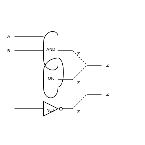
In the realm of digital electronics and computer science, Boolean algebra serves as a cornerstone for understanding the behavior of logic circuits and systems. The foundational operations of Boolean algebra—AND, OR, and NOT—act as the primary building blocks for constructing complex logical expressions. This subsection delves into these basic operations, elucidating their definitions, truth tables, and practical applications, paving the way for more sophisticated concepts in Boolean algebra.
AND Operation
The AND operation is a binary operation that yields a true output only when both inputs are true. This can be succinctly expressed as:
- \( A \) and \( B \) are the input variables.
- \( Z \) is the output of the AND gate.
The truth table for the AND operation is as follows:
| A | B | Output (Z) |
|---|---|---|
| 0 | 0 | 0 |
| 0 | 1 | 0 |
| 1 | 0 | 0 |
| 1 | 1 | 1 |
In practical terms, AND gates are utilized in applications like digital computing, where multiple conditions must be satisfied. For example, a security system could be designed to allow access only when both a key card is presented and the correct password is entered, showcasing the functionality of the AND operation in real-world scenarios.
OR Operation
The OR operation, in contrast to the AND operation, outputs true if at least one of the inputs is true. This relationship can be formally defined as:
- \( A \) and \( B \) are the input variables.
- \( Z \) is the output of the OR gate.
The truth table for the OR operation is shown below:
| A | B | Output (Z) |
|---|---|---|
| 0 | 0 | 0 |
| 0 | 1 | 1 |
| 1 | 0 | 1 |
| 1 | 1 | 1 |
OR gates are prevalent in various logical circuits, such as in alarm systems where triggering can occur based on one of several conditions being met, thereby enhancing the system’s overall responsiveness and flexibility.
NOT Operation
The NOT operation is a unary operation that inverses the input. It outputs true if the input is false and vice versa. The mathematical representation is:
- \( A \) is the input variable.
- \( Z \) is the output of the NOT gate.
The truth table for the NOT operation is straightforward:
| A | Output (Z) |
|---|---|
| 0 | 1 |
| 1 | 0 |
NOT gates play a vital role in the logic level adjustment within circuits, allowing systems to achieve complex logic functionalities effectively. This capability is often employed in signal processing to toggle states or to design inverting buffers.
Conclusion
Understanding the basic operations of AND, OR, and NOT is essential in Boolean algebra, as these concepts serve as the bedrock for designing and simplifying more intricate logical expressions and digital circuits. The practical applications of these operations are not limited to academic contexts but extend into real-world technology, influencing everything from computer architecture to everyday electronic devices.
1.3 Truth Tables and Logical Equivalence
Understanding Boolean Algebra is crucial for fields such as digital electronics, computer science, and logic design. Central to this understanding are truth tables and logical equivalence, both of which serve as foundational tools for analyzing and simplifying Boolean expressions.
Truth Tables: A Systematic Approach
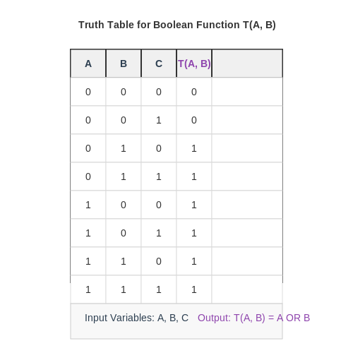
A truth table systematically enumerates the input combinations of Boolean variables and their corresponding outputs. It serves as a powerful visual tool that allows engineers and researchers to examine how logical expressions behave across all possible variable states.
For a simple two-variable Boolean function, say \( A \) and \( B \), the truth table would appear as follows:
Here, the function \( f(A, B) \) outputs 1 only when exactly one of the inputs is true, indicative of the logical XOR operation. Truth tables become increasingly essential as the number of variables increases, guiding logical reasoning in quantum circuits, digital design, and computer algorithms.
Building Logical Expressions from Truth Tables
Once a truth table is defined, the next step is to derive a logical expression that represents the relationship between the inputs and the output. This is typically achieved using the Sum of Products (SOP) method. Each combination of input variables that results in a true output (1) corresponds to a minterm in the expression.
For the previously shown truth table, the SOP representation can be constructed as follows:
- For \( A = 0, B = 1 \), the minterm is \( \bar{A}B \).
- For \( A = 1, B = 0 \), the minterm is \( A\bar{B} \).
Consequently, the SOP expression derived from the truth table is:
Logical Equivalence: Establishing Relationships
Logical equivalence refers to the condition where two Boolean expressions yield the same output for all input combinations. Understanding this concept is vital for simplifying Boolean functions and optimizing digital circuits.
To determine whether two Boolean expressions are equivalent, truth tables can again be employed. If two expressions result in identical outputs across all input combinations, they are logically equivalent.
For example, consider two expressions:
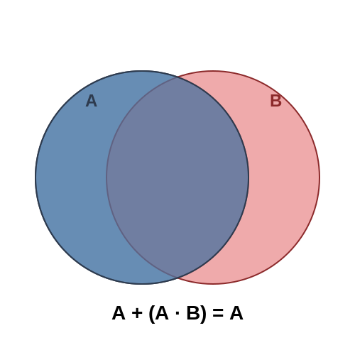
- Expression 1: \( A + AB \)
- Expression 2: \( A \)
Constructing a truth table for both expressions would show that they produce the same results:
Since both outputs match for all combinations of \( A \) and \( B \), we conclude:
Practical Applications
The utility of truth tables and logical equivalence extends far beyond academic exercises. They are vital in the design and optimization of complex digital circuits, allowing engineers to minimize the number of gates required for implementation, thus enhancing efficiency and reliability.
Truth tables also play a notable role in programming and software development; they help in the logical structuring of algorithms and decision-making processes. By understanding the logical connections among variables, engineers can design more robust and efficient systems.
In control systems and automated processes, logical equivalences provide insights into system behavior, thus enabling predictive modeling and preventive maintenance strategies.
Overall, mastering truth tables and the notion of logical equivalence equips engineers and researchers with essential tools for enhancing the performance of complex logical systems in the real world.
2. Idempotent Law
2.1 Idempotent Law
The Idempotent Law is a fundamental principle in the realm of Boolean algebra that reflects the distinct relationship between logical operations and set theory. Specifically, this law states that the result of applying the same logical operation more than once has no further effect beyond the first application. In formal terms, the Idempotent Law can be expressed as:
Here, \(A\) represents a Boolean variable which can take on values of either true (1) or false (0). The first equation corresponds to the operation of logical OR, while the second relates to logical AND. To put this into context:
- If we have a logical statement such as “It is raining OR it is raining,” the information conveyed is equivalent to simply stating, “It is raining.” Thus, the redundancy is eliminated.
- Similarly, in the statement “The light is ON AND the light is ON,” the outcome remains unchanged if we affirm that the light is ON.
The significance of the Idempotent Law extends beyond theoretical exercises; it plays a pivotal role in digital logic design, simplifying complex logical expressions that would otherwise require additional gates or components. By applying this law, engineers can streamline circuit designs, reduce resource consumption, and enhance performance. When simplifying Boolean functions, recognizing the Idempotent Law can lead to substantial reductions in terms of logic gates needed for implementation.
Practical Applications
The Idempotent Law has critical relevance in several engineering fields:
- Digital Electronics: Simplifying circuit designs is crucial for efficient system development, especially in devices like microcontrollers and processors, where space and power efficiency are paramount.
- Software Development: In programming and algorithm optimization, applying Boolean simplifications reduces computational complexity and enhances runtime efficiency.
- Data Compression: Algorithms for data manipulation benefit from the Idempotent Law, where certain redundancies can be eliminated, allowing for more efficient data structures and storage techniques.
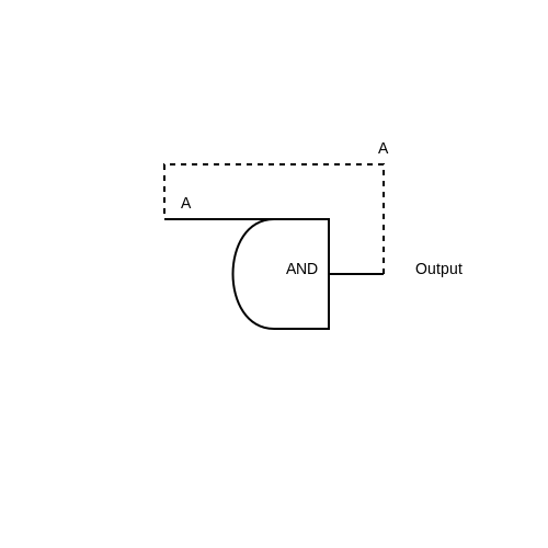
To illustrate further, consider a simple digital circuit where an input is fed into two identical gates. The outcome remains unchanged regardless of whether the input feeds into one or both gates, showcasing the practical utility of this law.
Example Circuit
Imagine an AND gate that receives its output back to itself. If we apply the input signal \(A\) directly to the gate:
Thus, if \(A=1\), the output remains 1 regardless of duplicating the input in terms of gates used. This segmentation underlines how the Idempotent Law can optimize designs.
In conclusion, understanding the Idempotent Law empowers engineers and scientists to create more efficient designs and algorithms, reducing redundancy and enhancing clarity in logical expressions.
2.2 Domination Law
The Domination Law is a fundamental principle in Boolean algebra that significantly simplifies expressions involving logical operations. This law states that certain inputs, when combined with others using the basic operations of AND and OR, will dominate the outcome of the expression, rendering redundant the lesser inputs. The two principal facets of the Domination Law can be summarized as follows:
- A + 1 = 1: This expression indicates that when a variable is ORed with 1, the result will always be 1, regardless of the value of the variable A.
- A · 0 = 0: Here, when a variable is ANDed with 0, the output is always 0, irrespective of A's state.
Understanding the implications of the Domination Law is not just an exercise in theoretical logic; it has profound practical applications, particularly in digital circuit design and optimization. By applying these simplifications, engineers can reduce the number of gates required in a circuit, thus minimizing power consumption and improving the efficiency of digital systems.
Mathematical Derivation
To illustrate the effects of the Domination Law, we'll consider the logical expressions inherent in both the OR and AND operations. Let's derive the outcomes step-by-step:
1. The OR operation, A + 1
Suppose A can take the values 0 or 1. We can construct a truth table to demonstrate how A interacts with 1:
| A | A + 1 |
|---|---|
| 0 | 1 |
| 1 | 1 |
As can be seen, regardless of the value of A, the output is consistently 1. Therefore, A + 1 = 1 illustrates the essence of the Domination Law for the OR operation.
2. The AND operation, A · 0
Now, let's analyze the AND operation through a similar truth table:
| A | A · 0 |
|---|---|
| 0 | 0 |
| 1 | 0 |
From this table, we see that no matter the value of A, the output remains 0. Thus, A · 0 = 0 exemplifies the Dominating characteristic of the AND operation.
Real-World Applications
In the context of digital electronics, the Domination Law is crucial for simplifying complex logic circuits. For instance, if a digital design has redundant paths or gates that do not affect the ultimate output, engineers can leverage the Domination Law to eliminate these components, leading to a more streamlined and efficient design. This reduction is beneficial not only in terms of space and component count but also for the reliability and speed of the circuit.
Furthermore, the application of the Domination Law is particularly significant in combinational unit design, such as multiplexers and adders, enhancing the overall optimization of digital systems.
As we continue exploring the intricacies of Boolean algebra, it becomes clear that laws like Domination form the foundation for more complex operations and simplifications that are vital in both theoretical and applied contexts.
2.3 Identity Law
The Identity Law is a fundamental aspect of Boolean algebra that plays a crucial role in the simplification of logical expressions and the design of digital circuits. At its core, this law illustrates how certain combinations of variables and constants yield predictable results, thus enabling more efficient computation. To understand the Identity Law, let's explore its formulation. In Boolean algebra, we are primarily concerned with two constants: 0 (representing false) and 1 (representing true). The Identity Law states that for any Boolean variable \( A \): $$ A \cdot 1 = A $$ $$ A + 0 = A $$ These expressions can be interpreted as follows: - When you AND a Boolean variable \( A \) with 1, the result is \( A \). This is because \( A \) must be true (1) in order to satisfy the AND condition. - Conversely, when you OR a Boolean variable \( A \) with 0, it does not alter the value of \( A \); it remains as \( A \). The implications of the Identity Law extend well beyond simple theoretical concepts. In practical applications, engineers often engage in simplifications of complex logic circuits using the Identity Law. For example, when designing digital systems, removing redundant logic gates that yield no change—such as those adhering to the Identity Law—can significantly reduce the cost and complexity of circuits. Consider a detailed example within a circuit design context. Imagine you have a logical expression derived from a circuit that involves several gates. By applying the Identity Law, equations like \( X \cdot 1 \) can be simplified directly to \( X \). This means that any extra gating (like connecting a circuit to an AND gate with a constant logic high) can be eliminated, streamlining the circuit and enhancing performance. Moreover, this law serves as a stepping stone towards mastering more complex laws in Boolean algebra such as the Domination Law and the Idempotent Law, which further explore the simplifications possible in logical expressions. In summary, the Identity Law is not merely an abstract mathematical rule; it lays the foundation for practical engineering solutions, making it indispensable for anyone involved in electronic design or logical computation. Through its application, we witness the transformational effects of simplification, ultimately leading to more effective and efficient systems. As we move forward, we will delve deeper into how the Identity Law interacts with other fundamental laws of Boolean algebra, reinforcing our understanding of the simplifications available at our disposal.2.4 Complement Law
The complement law is a fundamental principle in Boolean algebra that governs the interaction between a variable and its complement. A variable, usually denoted as \( A \), can take a value of either 1 (true) or 0 (false). The complement of \( A \), denoted as \( A' \) or \( \bar{A} \), represents the opposite state, where \( A' = 1 \) if \( A = 0 \), and \( A' = 0 \) if \( A = 1 \). This duality plays a major role in simplifying Boolean expressions and understanding digital logic systems.
Understanding the Complement Law
The complement law consists of two primary expressions that illustrate how a variable and its complement interact:
1. Identity with the complement: For any Boolean variable \( A \), it follows that: $$ A + A' = 1 $$ This indicates that when a variable is combined with its complement via the OR operation, the result is always true (1) regardless of the value of \( A \). 2. Identity with AND operation: Conversely, the expression involving the AND operation is given by: $$ A \cdot A' = 0 $$ This equation states that no matter what value \( A \) takes, the AND operation between a variable and its complement yields false (0).These identities highlight a crucial aspect of Boolean algebra: the completeness of the logical framework. In essence, every Boolean algebra can be defined through these fundamental relationships, providing a pathway to more complex logic expressions.
Applications of the Complement Law
In practical settings, the complement law has significant implications, especially in digital circuit design and optimization. By applying the complement law, engineers can:
- Simplify Logic Circuits: The application of these identities can lead to a reduction in the number of gates required in a circuit, thus decreasing both cost and complexity.
- Design Efficient Algorithms: In computing, using the complement law aids in developing algorithms that minimize processing time by simplifying logical conditions.
- Facilitate Error Correction: In error detection and correction mechanisms, understanding the relationship between a binary variable and its complement allows for the design of reliable systems that ensure data integrity.
Historical Context
The foundations of the complement law in Boolean algebra were laid by the mathematician George Boole in the mid-19th century. Boole's work on symbolic logic provided the basis for what would later evolve into the digital logic that underpins computer architecture today. Understanding the complement law allows researchers and engineers not only to appreciate the theoretical framework laid down by Boole but also to apply it in modern computing and electronics effectively.
As we delve deeper into the nuances of Boolean algebra, it becomes apparent that the complement law is a stepping stone toward more sophisticated operations such as negation and composite functions, enabling a thorough exploration of digital logic design.
2.5 Distributive Law
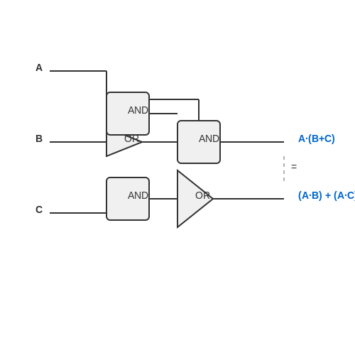
Understanding the Distributive Law in Boolean algebra is essential for simplifying logical expressions and designing efficient digital circuits. The Distributive Law states that for any Boolean variables A, B, and C:
This law allows us to distribute AND operations over OR operations, and vice versa, which is pivotal in transforming complex logical expressions into simpler forms that are easier to analyze and implement. The dual nature of Boolean algebra—where operations can be interchanged—offers significant flexibility in logical expressions.
Proof of the Distributive Law
To illustrate the validity of the Distributive Law, let’s consider each equation separately. We’ll start with the first expression:
We can utilize a truth table for further clarification. In a truth table, we list all possible combinations of the values of A, B, and C (which can be either 0 or 1), and then calculate the left-hand side and the right-hand side of the equation.
The truth table for the first expression is as follows:
| A | B | C | A · (B + C) | (A · B) + (A · C) |
|---|---|---|---|---|
| 0 | 0 | 0 | 0 | 0 |
| 0 | 0 | 1 | 0 | 0 |
| 0 | 1 | 0 | 0 | 0 |
| 0 | 1 | 1 | 0 | 0 |
| 1 | 0 | 0 | 0 | 0 |
| 1 | 0 | 1 | 1 | 1 |
| 1 | 1 | 0 | 1 | 1 |
| 1 | 1 | 1 | 1 | 1 |
On analyzing the truth table, it’s evident that both sides yield the same output for all combinations of A, B, and C, thereby confirming the first part of the Distributive Law.
The second expression can be similarly validated:
We again employ a truth table to establish the equality:
| A | B | C | A + (B · C) | (A + B) · (A + C) |
|---|---|---|---|---|
| 0 | 0 | 0 | 0 | 0 |
| 0 | 0 | 1 | 0 | 0 |
| 0 | 1 | 0 | 0 | 0 |
| 0 | 1 | 1 | 1 | 1 |
| 1 | 0 | 0 | 1 | 1 |
| 1 | 0 | 1 | 1 | 1 |
| 1 | 1 | 0 | 1 | 1 |
| 1 | 1 | 1 | 1 | 1 |
Again, this truth table confirms that the two expressions are indeed equivalent for all possible input combinations.
Applications in Digital Design
The Distributive Law is not just an abstract mathematical concept; it has real-world implications in the design and optimization of digital circuits. Engineers often use this principle to minimize the number of gates required in circuit designs, significantly impacting operational efficiency.
Practical applications include:- Simplifying logic circuits, which leads to cost-effective designs.
- Enhancing speed by reducing the propagation delay through fewer gates.
- Facilitating easier troubleshooting and modifications in existing systems.
In conclusion, the Distributive Law is a cornerstone in Boolean algebra, providing powerful tools for simplification and efficiency in electronic design. Its applications continue to evolve alongside advancements in logic design, making understanding this law critical for any engineer or researcher in the field.
3. Algebraic Manipulations
Boolean Algebra Simplification
3.1 Algebraic Manipulations
In the realm of digital logic design and computer science, Boolean algebra serves as a foundational tool for simplifying complex logical expressions. This subsection delves into the algebraic manipulations utilized in Boolean algebra, which not only facilitate the simplification of expressions but also impact the performance and efficiency of digital circuits. Boolean algebra operates on binary variables, employing operators such as AND, OR, and NOT, symbolized by multiplication (*), addition (+), and negation (') respectively. The profound utility of Boolean algebra lies in its ability to reduce the complexity of digital circuits, thereby enhancing their reliability and performance. To begin, let's explore several fundamental laws of Boolean algebra that govern these manipulations: 1. Identity Law: - \( A + 0 = A \) - \( A \cdot 1 = A \) 2. Null Law: - \( A + 1 = 1 \) - \( A \cdot 0 = 0 \) 3. Complement Law: - \( A + A' = 1 \) - \( A \cdot A' = 0 \) These foundational laws simplify the design process when dealing with circuit components. For instance, consider the expression \( A \cdot 1 \). By applying the identity law, we quickly simplify it to \( A \), demonstrating how Boolean algebra can streamline reasoning in complex electronic designs. Another critical aspect of simplifying Boolean expressions is through the Absorption Law, which offers significant reductions: - \( A + AB = A \) - \( A(A + B) = A \) For example, simplifying the expression \( A + AB \): 1. By identifying the expression as \( A + AB \), we recognize that \( A \) (the first term) dominates due to its presence in both terms. 2. As per the Absorption Law, the entire expression reduces to \( A \). This reduction not only reduces the number of gates required but also minimizes propagation delay in circuit design. In addition, consider the Distributive Law, which further aids in simplification: - \( A(B + C) = AB + AC \) To illustrate, let's simplify an example expression: $$ X = A(B + C) + A'D $$ 1. By applying the Distributive Law, we expand \( X \) to: $$ X = AB + AC + A'D $$ This step highlights a critical juncture where we can assess the potential for further simplifications based on laws applicable to the remaining terms. The practical relevance of these algebraic manipulations is profound and far-reaching. In digital circuit design, every simplification corresponds to reductions in hardware requirements, power consumption, and cost. For instance, reducing the count of logic gates in a circuit not only lowers fabrication costs but also enhances speed and energy efficiency. Moreover, such algebraic techniques are vital for designing fault-tolerant circuits, where redundancy can be minimized through effective simplifications. In conclusion, the art of algebraic manipulation in Boolean algebra is not merely an academic exercise; it is an essential skill for engineers and researchers alike, impacting the efficiency and effectiveness of digital systems. Mastery of these laws allows for the design of optimized systems that uphold reliability and performance — a necessity in the increasingly complex landscape of digital technology.Further Explorations
For those interested in a deeper exploration of Boolean algebra and its applications in digital design, numerous resources and textbooks provide excellent insights and advanced discussions on this topic.3.2 Karnaugh Maps
Boolean algebra serves as the backbone for digital logic design, allowing for the simplification of logical expressions. Among various techniques for simplifying Boolean expressions, Karnaugh Maps (K-maps) provide a visual method for minimizing these algebraic equations. This section delves into the concept of Karnaugh Maps, demonstrating their construction and application in logic circuit simplification.
Understanding Karnaugh Maps
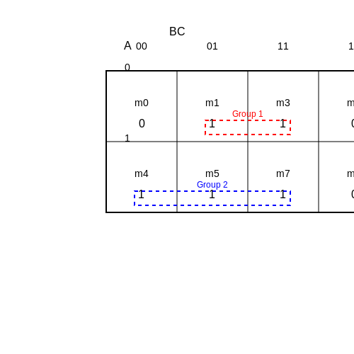
A Karnaugh Map is a graphical representation of truth tables. It enables easy visual identification of opportunities to simplify Boolean functions. Each cell in a K-map corresponds to a minterm of the function being analyzed, representing the outputs for different combinations of input states.
The beauty of K-maps lies in their ability to reveal groupings of adjacent cells that represent common factors. By grouping these cells, you can derive simplified Boolean expressions more efficiently than traditional algebraic methods.
Constructing a Karnaugh Map
K-maps can be constructed for functions with up to six variables. The procedure follows these steps:
- Determine the number of variables: For n variables, a K-map will have \(2^n\) cells.
- Label the K-map: Arrange the variables such that only one variable changes between adjacent cells. A common method is using Gray code.
- Fill in the cells: According to the truth table, place '1's in the cells corresponding to the minterms of the function.
Example of a Two-Variable K-map
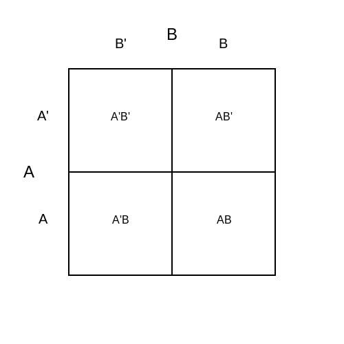
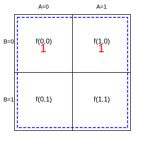
Consider a simple two-variable function, \( f(A, B) \). The K-map for this function will have four cells, as follows:
Here, each cell represents a combination of A and B, with the function’s outputs filled in accordingly. For instance, if \( f(0,0) = 1 \), it indicates that the output is high when both inputs are at low state.
Grouping in K-maps
The next step is to identify groups of '1's. Groups can consist of 1, 2, 4, or 8 cells, and must be rectangular in shape. Groups can wrap around the edges of the K-map, which allows greater flexibility in simplifying the expression. The ideal goal is to minimize the number of groups while maximizing the cell coverage.
For instance, in a K-map representing the function:
If we can group the two '1's together, we can simplify the function to:
Practical Applications
Karnaugh Maps are widely utilized in fields ranging from computer science to electrical engineering. They are particularly useful in the design of digital circuits, where efficient logic design can significantly reduce the complexity and cost of hardware.
By minimizing the number of logical gates necessary for a given circuit, K-maps enable the creation of faster, more reliable, and power-efficient components. This aspect is crucial in areas like embedded systems and automated manufacturing, where efficiency translates into improved performance and reduced costs.
In summary, Karnaugh Maps offer an effective method for visualizing and simplifying Boolean expressions, which in turn has substantial implications for modern logic design and electronics.
3.3 Consensus Theorem
The Consensus Theorem is a critical concept in Boolean algebra, particularly when it comes to the simplification of logical expressions. This theorem aids in reducing the complexity of Boolean expressions that are widely used in digital logic design, circuit simplification, and various applications in computer architecture.
Understanding the Consensus Theorem
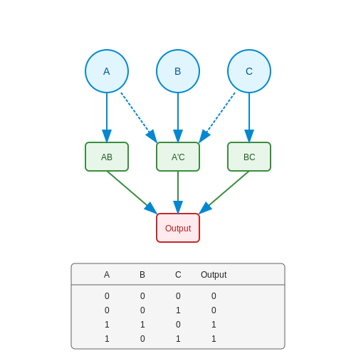
The Consensus Theorem states that for any three variables \(A\), \(B\), and \(C\), the expression can be simplified as follows:
In this equation, \(AB\) and \(A'C\) represent the "consensus" outcomes of combinations where at least one term must be true. The term \(BC\) is redundant; it does not contribute to the overall value of the expression since either \(AB\) or \(A'C\) will ensure the output remains unchanged regardless of \(C\).
Mathematical Derivation
To understand how the Consensus Theorem operates, we can derive it step-by-step:
- Start with the original expression: AB + A'C + BC.
- Notice that \(BC\) can be expressed by factoring out a common term:
- The combined expression can be approached using the Distributive Law. By rearranging the terms:
- Now we recognize that terms \(A'BC\) do not affect the existing contributions of \(AB\) and \(A'C\). Therefore, we can eliminate \(BC\):
Thus, the Consensus Theorem simplifies expressions where certain conditions apply, eliminating unnecessary complexities.
Real-World Applications
In practical scenarios, the Consensus Theorem is especially relevant in the design and optimization of digital circuits. Consider the following applications:
- Digital Circuit Design: Engineers use the Consensus Theorem to minimize the number of gates in a circuit, reducing cost and power consumption.
- Verification and Validation: The theorem assists in verifying logic circuits, ensuring that all possible input combinations yield the correct output.
- Software Algorithms: In computer algorithms that rely on Boolean logic, simplifying expressions can lead to enhanced performance and decreased execution time.
Overall, the Consensus Theorem plays a pivotal role in the field of electronics, contributing significantly toward sophisticated logic design and functional hardware implementation. Through reducing redundancy, one can achieve optimized solutions that are both reliable and efficient.
3.4 Quine-McCluskey Method
The Quine-McCluskey method serves as a systematic approach for simplifying Boolean expressions, particularly useful when dealing with functions of more than four variables. Unlike Karnaugh maps, which become increasingly complex with larger variable sets, this tabular method allows for a more generalized solution, paving the way for computer-aided simplifications.
The Principles Behind the Quine-McCluskey Method
To grasp the essence of the Quine-McCluskey method, it is vital to understand that it operates on the principles of combinatorial optimization and pattern recognition. The technique is systematic, employing two primary steps: the generation of prime implicants and the construction of a prime implicant chart.
Step 1: Generating Prime Implicants
The first step involves the creation of a truth table from the given Boolean expression. Each minterm (a term that yields a true output) is represented by a binary number, where each bit corresponds to a variable. The method relies on grouping these minterms by their Hamming weight, which counts the number of ones in the binary representation. The grouping helps in identifying potential implicants by comparing binary numbers differing by exactly one bit.
For instance, consider the minterms:
- Minterm 0: 0000
- Minterm 1: 0001
- Minterm 3: 0011
- Minterm 7: 0111
The groupings would appear as follows:
- Group 0 (0 ones): 0
- Group 1 (1 one): 1
- Group 2 (2 ones): 3
- Group 3 (3 ones): 7
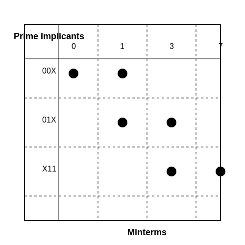
By systematically comparing these, pairs can be formed that allow for simplification via consensus terms (e.g., from 1 and 3 produce 00X, where X represents any digit).
Step 2: Constructing the Prime Implicant Chart
Once all prime implicants have been identified, the next step is to compile them into a prime implicant chart. This chart illustrates which minterms are covered by each prime implicant. The goal here is to uncover the essential prime implicants—those that cannot be omitted without losing the ability to express the original function.
A column corresponds to each minterm, while each row represents a prime implicant. A filled cell indicates that the implicant can cover the minterm; thus, the chart acts as a visual representation of the relationships among conditions.
The selection process may involve various strategies such as covering the max number of minterms with minimum implicants, often leading to the identification of prime implicants that are crucial to the minimized expression.
Real-World Applications
The Quine-McCluskey method is particularly relevant in the domain of digital circuit design. With the ever-increasing complexity of electronic systems, engineers utilize this approach to design efficient circuits that minimize resource consumption, thus optimizing performance and reducing cost. This method is particularly applicable in applications where software tools like logic synthesis engines can be combined with it to automate the design process.
Furthermore, with the rise of programmable logic devices (PLDs) and complex programmable logic devices (CPLDs), the demand for robust and efficient Boolean simplifications continues to grow, underscoring the enduring significance of the Quine-McCluskey method in modern electronics.
4. Digital Circuit Design
4.1 Digital Circuit Design
In the realm of digital electronics, the notion of Boolean algebra simplifies complex logical expressions, which is fundamental for efficient digital circuit design. This subsection delves into the application of Boolean algebra in crafting digital circuits, fostering an understanding of how theoretical concepts translate into practical designs.Understanding Boolean Functions
A Boolean function is a mathematical representation of logical expressions. Each function takes binary values (0 or 1) and outputs a binary value based on specific logical operations. The elementary operations include AND, OR, and NOT, forming the backbone of digital circuit logic. For example, let’s denote a Boolean function as: $$ F(A, B, C) = A \cdot B + \overline{C} $$ where: - \( A \cdot B \) represents the AND operation, - \( \overline{C} \) represents the NOT operation applied to \( C \), - \( + \) signifies the OR operation. Each combination of inputs results in a specific output, which can be represented using logic gates directly in a circuit.Minimization of Logic Expressions
The practical utility of Boolean algebra emerges prominently in the minimization of logic expressions. Minimization not only reduces the number of gates required but also optimizes circuit performance in terms of speed and power consumption. Techniques such as Karnaugh maps and the Quine-McCluskey algorithm can systematically simplify such expressions. Consider simplifying the Boolean expression: $$ F = AB + A\overline{C} + B\overline{C} $$ 1. Identify common factors: Notice that both terms \( A\overline{C} \) and \( B\overline{C} \) share \( \overline{C} \). 2. Factor out common terms: $$ F = AB + \overline{C}(A + B) $$ 3. Check for redundancy: If testing various input combinations, one could further validate if one term is unnecessary in the context of circuit constraints. Utilizing tools such as Karnaugh maps offers a visual method to group terms to achieve this albeit in more complicated scenarios with ease.Real-World Applications
In practice, digital circuit design plays a pivotal role across multiple domains, from computer architecture to embedded systems. One expensive aspect in large-scale integration circuits is gate count; hence, accurate and minimal boolean expressions become paramount. For instance, in the design of an ALU (Arithmetic Logic Unit), the ability to represent complex logical relationships with the minimum number of gates can significantly lower production costs and increase performance. Moreover, modern applications such as FPGA (Field-Programmable Gate Array) implementations utilize these simplified Boolean expressions to configure hardware dynamically, allowing flexibility in design and function.Conclusion
In summary, understanding and applying Boolean algebra in digital circuit design is fundamental for engineers and researchers looking to innovate and optimize electronic systems. The blend of rigorous theoretical knowledge and practical skills in simplification facilitates the development of efficient, cost-effective, and high-performance circuits. This foundation sets the stage for further exploration of topics such as sequential circuit design and state machines, which build upon these preliminary principles.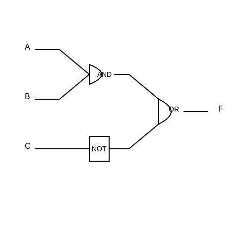
4.2 Minimization of Logic Gates
In the realm of digital design, the minimization of logic gates represents a cornerstone in creating efficient and effective systems. Through the application of Boolean algebra, designers can simplify complex logical expressions, thereby reducing the number of gates required in a circuit. This reduction not only enhances performance by decreasing propagation delay and power consumption but also promotes the reliability and cost-effectiveness of electronic components.
Understanding the Basics of Logic Gate Minimization
At its core, minimization involves representing a logical function in the simplest form possible. This simplification manifests in fewer gates, which translates to less physical space and reduced resource expenditure. A fundamental understanding of Boolean algebra and the laws governing it is essential for achieving this simplification. The basic laws include:
- Identity Law: \( A + 0 = A \) and \( A \cdot 1 = A \)
- Null Law: \( A + 1 = 1 \) and \( A \cdot 0 = 0 \)
- Idempotent Law: \( A + A = A \) and \( A \cdot A = A \)
- Complement Law: \( A + \overline{A} = 1 \) and \( A \cdot \overline{A} = 0 \)
These postulates lay the foundational framework utilized in various minimization strategies.
Minimization Techniques
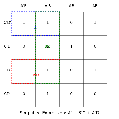
Several techniques exist for minimizing logic gates, most notably the Karnaugh Map (K-map) and Quine-McCluskey algorithm. Both methods derive from Boolean expressions yet adopt different approaches to achieve the same end. The K-map is particularly intuitive, allowing for visual grouping of terms, whereas the Quine-McCluskey algorithm lends itself well to systematic simplification, especially for complex expressions involving many variables.
Karnaugh Maps
The K-map is a visual representation of truth tables, where adjacent cells correspond to inputs that differ by only one bit. To use a K-map:
- Construct a truth table for the expression.
- Fill out the K-map with '1's corresponding to the outputs for 'true' input combinations.
- Group the '1's in the K-map into the largest possible rectangles (groups of 1, 2, 4, or 8 cells).
- Write down the simplified expression, ensuring you include all variables that persist at the group level.
For example, group \( A'B \), \( AB \), and \( A'B' \) to yield a simpler representation.
Quine-McCluskey Algorithm
The Quine-McCluskey algorithm, a systematic tabulation method, starts similarly with a truth table but replaces the K-map's visual appeal with logical table listings. The steps are:
- List minterms for the function and group them by the number of '1's.
- Iterate through groups, combining terms that differ by a single bit to form prime implicants.
- Create a prime implicant chart.
- Select the essential prime implicants to form the final minimal expression.
This method excels in automation and can handle more complex scenarios where K-maps become unwieldy.
Practical Applications of Logic Gate Minimization
The advancements in logic gate minimization have had a profound impact on the design of Integrated Circuits (ICs)Field Programmable Gate Arrays (FPGAs). In modern microprocessors, optimized gate configurations lead to notable enhancements in speed and energy efficiency. Real-world applications span across diverse domains from consumer electronics to telecommunications, where speed and reliability are paramount.
Conclusion
The minimization of logic gates is not merely an academic concept; it is a practical necessity in modern electronic design. Through the application of Boolean algebra techniques such as K-maps and the Quine-McCluskey algorithm, engineers can optimize their circuits. Understanding and leveraging these principles can lead to innovations in device performance, making logic gate minimization a critical skill for any advanced electronics engineer.
4.3 Implementation of Combinational Circuits
Understanding how to implement combinational circuits is essential in advanced digital system design. Combinational circuits are circuits where the output is directly driven by their current inputs, without any memory elements requiring synchronization. The combination of Boolean algebra simplification techniques is pivotal in optimizing these circuits for efficiency and performance.
When implementing a combinational circuit, the process begins with deriving the truth table from the problem specification. Once the truth table is established, it can be translated into a Boolean expression, which can often be simplified using Boolean algebra rules. The simplified expressions serve as a roadmap towards designing more efficient circuit implementations.
Truth Table Creation and Boolean Expression Formation
The truth table captures all possible input combinations along with their corresponding output values. For example, consider a simple combinational logic problem involving three inputs, A, B, and C. The outputs can be systematically listed in a truth table format:
| A | B | C | Output (F) |
|---|---|---|---|
| 0 | 0 | 0 | 0 |
| 0 | 0 | 1 | 1 |
| 0 | 1 | 0 | 1 |
| 0 | 1 | 1 | 1 |
| 1 | 0 | 0 | 0 |
| 1 | 0 | 1 | 0 |
| 1 | 1 | 0 | 1 |
| 1 | 1 | 1 | 1 |
From the above truth table, Boolean expressions can be derived. One common approach uses the minterms associated with the output value of 1. In this case, the expression is:
Boolean Simplification Techniques
With the Boolean expression in hand, we can apply Boolean algebra rules such as:
- Identity Law: A + 0 = A; A * 1 = A
- Null Law: A + 1 = 1; A * 0 = 0
- Idempotent Law: A + A = A; A * A = A
- Complement Law: A + A' = 1; A * A' = 0
Applying these laws to our initial expression will yield a more simplified form that leads to a practical circuit design. As an example, after using combination laws and absorbing terms:
Implementation in Hardware
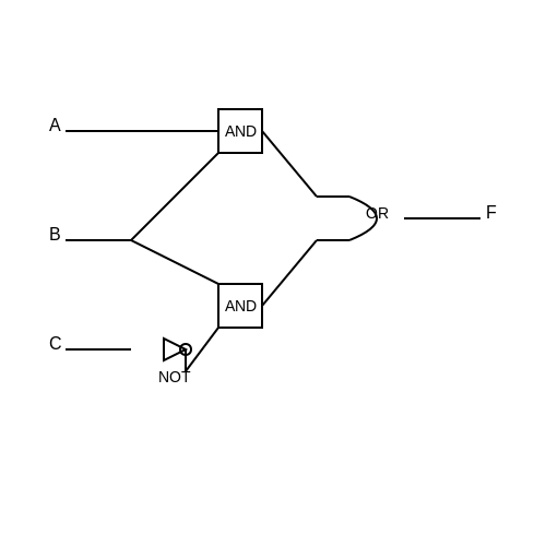
The simplified expression can then be used to design the hardware implementation using basic logic gates:
- AND gates: To implement products of variables.
- OR gates: To combine those products to form the output.
- NOT gates: To create the complements required in the expression.
The configuration of these gates based on the simplified expression is crucial for minimizing physical space and improving operational efficiency. For instance, if a circuit designed from a complex Boolean expression comprises more gates than necessary, not only does it occupy more silicon area, but it can also lead to limitations in speed and reliability.
In conclusion, the implementation of combinational circuits leveraging Boolean algebra simplification significantly enhances both design efficiency and performance metrics. By starting from a truth table to a simplified Boolean expression and translating that to an optimized hardware configuration, engineers create robust solutions tailored to meet specific operational criteria.
5. Misapplication of Laws
5.1 Misapplication of Laws
In the domain of electronic and logical systems, Boolean algebra serves as a fundamental framework for simplifying and analyzing logical expressions. As with any powerful tool, however, its strategic application demands a nuanced understanding. Misapplication of Boolean laws can lead to erroneous conclusions, potentially undermining the reliability of digital circuits and systems design. This subsection will explore common pitfalls in the application of Boolean laws and offer guidelines for avoiding these missteps.
Understanding Boolean Laws
Before delving into misapplications, it is essential to establish a solid grasp of the principal Boolean laws. The key laws include:
- Identity Law: A + 0 = A and A · 1 = A
- Null Law: A + 1 = 1 and A · 0 = 0
- Complement Law: A + A' = 1 and A · A' = 0
- Idempotent Law: A + A = A and A · A = A
- Domination Law: A + 1 = 1 and A · 0 = 0
While these laws provide a framework for logical operations, misapplying them can result in significant errors in circuit design and logic simplification. Below are several ways in which engineers and researchers may fall prey to incorrect usage.
Common Misapplications
Overgeneralization of Laws
One frequent error involves the overgeneralization of laws across more complex expressions. For instance, while the Complement Law applies universally, combining it with non-complemented variables can lead to mistakes. Consider the expression:
While simplification appears valid, failing to validate each step can mislead the engineer into assuming that it holds in all circumstances, ultimately resulting in suboptimal circuit behavior.
Ignoring Variable Relationships
Another pitfall is ignoring the inherent relationships between variables, particularly in multi-variable expressions. For example, the application of the Idempotent Law may seem straightforward, yet it can overlook contextual relationships that can affect the simplification outcome. As an illustration, observe the expression:
Here, the proper application of Boolean principles necessitates consideration of the roles played by both A and B throughout the expression's derivation.
Improper Distribution and Association
Misapplying the distributive property can obscure the values and lead to faulty logic conclusions. For instance, while the Distributive Law states:
it is vital to examine whether the distribution genuinely reflects the original intent of the logical setup. The erroneous assertion that $$(AB + AC)$$ equates to $$(A + B)(A + C)$$—while tempting—can lead to significant errors in both logical deductions and circuit implementations.
Practical Impact of Misapplication
The implications of misapplying Boolean laws can range from minor inefficiencies to catastrophic system failures. For example, in digital circuit design, an incorrectly simplified expression can lead to increased power consumption, delayed response times, or complete logic system failures. In automated systems reliant on Boolean conditions, such errors can yield dangerously unexpected behaviors.
Conclusion
Through understanding the nuances of Boolean algebra laws and the common misapplications therein, engineers and researchers can improve their logical deduction skills. By maintaining a critical eye on how these laws are applied, it is possible to avoid missteps that could have dire consequences in real-world applications.
Next, we will explore specific strategies to enhance Boolean algebra simplification capabilities, thereby ensuring both accuracy and efficiency in logical designs.
5.2 Errors in Karnaugh Maps
In the realm of digital logic design, Karnaugh Maps (K-maps) serve as powerful tools for visualizing and simplifying Boolean expressions. However, as advantageous as K-maps can be, their application is susceptible to various types of errors that may stem from user misinterpretation or misplacement of terms. This section delves into common sources of error when working with K-maps, analyzing their importance, implications, and how to avoid them in practice.Understanding Errors in K-maps
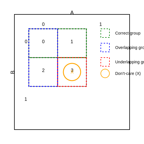
Karnaugh Maps allow engineers and physicists to minimize Boolean functions quickly, but human error can often compromise the effectiveness of this method. Errors can arise in several forms, including:- Placing Minterms Incorrectly: During the process of plotting minterms on a K-map, mispositioning these values can lead to incorrect grouping and, ultimately, inaccurate simplification. The K-map layout requires precise adherence to Gray code order—a binary numbering system where two successive values differ by a single bit.
- Overlapping or Underlapping Groups: When grouping ones in a K-map, it’s crucial to account for all adjacent ones without missing any potential combinations. Overlapping groups can result in redundancy in the final expression, while underlapping groups can lead to transformed, improper expressions that may require additional gates when implemented in hardware.
- Ignoring Don’t-Care Conditions: In cases of combinational circuits, don’t-care conditions can significantly ease the simplification process. Neglecting to incorporate these conditions leads to a suboptimal solution and unnecessary complexity in circuit design.
- Inadequate Understanding of Variable Relation: Users must ensure they have an accurate grasp of how variables interact within the K-map matrix. Not understanding variable relationships can lead to incorrect assumptions about which variables can be grouped or ignored.
Practical Implications
Errors in K-map simplifications can cascade into substantial real-world issues, including increased circuit complexity, higher costs, and potential performance inefficiencies in digital systems. For instance, if a digital circuit that should execute a simple task is instead overloaded with unnecessary logic gates due to improper K-map interpretation, it could lead to increased power consumption or operational delays. Designers must realize the importance of verifying K-map results through multiple methods—such as software simulations or manual calculations—to ensure that no error persists unnoticed. The use of simulation tools enabled by software packages can provide immediate feedback, further streamlining the verification process.Avoiding Common Errors
To mitigate the likelihood of encountering these pitfalls, the following strategies are recommended:- Double-Check Minterm Positions: Before finalizing the K-map, confirm that each minterm aligns correctly with the corresponding Gray code position.
- Validate Group Formations: Use tactile techniques such as highlighters or visual aids to ensure clear and distinct groups are formed, extending across rows and columns as necessary.
- Leverage Software Tools: Incorporating logic design software that offers K-map functionalities can significantly reduce human error by providing visual validation of input and output results.
- Consult Peers for Verification: Peer review within a collaborative workspace may uncover individual biases in interpretation, leading to a more robust design process.
5.3 Neglecting Edge Cases
In the realm of Boolean algebra simplification, the term 'neglecting edge cases' refers to a methodological choice wherein certain less probable or specialized input scenarios are deliberately excluded from consideration during the simplification process. Understanding the implications of this approach is critical, particularly when working on efficiency optimizations in digital design.
Boolean expressions, which can often exhibit complex behaviors depending on the values of their variables, can be simplified using a variety of rules and principles. However, certain situations might lead to additional complexity that, while theoretically significant, rarely impacts the practical performance of a digital circuit. This is where edge cases come into play.
Understanding Edge Cases in Boolean Expressions
Edge cases are those conditions at the boundaries of normal operational parameters. These typically include scenarios involving low probabilities of occurrence, such as the behavior of a digital circuit when it encounters input configurations that are unlikely to be utilized during normal operation. For instance, consider a security system designed to recognize human faces; a potential corner case might arise from inputting low-quality images not representative of the device's usual operational context.
Neglecting these edge cases can streamline the design process and lead to performance enhancements. However, it does come with risks. The simplified design may render the system insensitive to certain functional anomalies that could arise under rare circumstances.
Benefits and Drawbacks of Neglecting Edge Cases
To navigate the decision of neglecting edge cases effectively, one must weigh the benefits against potential drawbacks:
- Benefits:
- Enhanced Performance: Simplification often yields faster processing times and reduced resource usage in terms of logic gates and circuit complexity.
- Reduced Cost: Fewer components in a circuit lead to lower manufacturing costs and a smaller footprint on a chip.
- Increased Clarity: Simplified Boolean expressions are easier to understand, which is particularly advantageous during debugging and sharing among design teams.
- Drawbacks:
- Loss of Functionality: Ignoring edge cases may result in systems that fail under non-standard conditions, leading to malfunctions that could endanger reliability.
- Maintenance Complexity: Code or digital systems that do not account for all possible inputs may require more extensive maintenance later when unexpected use cases surface.
Strategies for Identifying Edge Cases
To effectively identify edge cases that may not significantly impact overall performance, engineers can deploy several strategies, including:
- Simulation: Utilize simulation tools to evaluate all possible inputs, including extreme cases. Identifying which inputs lead to significant deviations in output can help in deciding which edge cases can be neglected.
- Statistical Analysis: Analyze historical data to ascertain how infrequently certain input combinations occur in real-world scenarios. Inputs that show minimal occurrence can often be considered for neglect.
- Peer Reviews: Collaborate with peers to brainstorm possible edge cases during the design phase, ensuring that the team holds a collective understanding of what to neglect and what to retain.
In summary, while neglecting edge cases can streamline the process of Boolean algebra simplification, making this decision should involve a careful evaluation of risks and an understanding of system requirements. This balance is particularly crucial in environments where reliability is paramount.
6. Recommended Textbooks
6.1 Recommended Textbooks
- Digital Design by M. Morris Mano and Michael D. Ciletti — This well-regarded textbook provides a comprehensive introduction to digital logic design. It covers Boolean algebra in depth, offering practical examples and problem-solving techniques suitable for advanced students.
- Logic and Computer Design Fundamentals by M. Morris Mano and Charles R. Kime — This book explores Boolean algebra simplification in the context of computer design. Readers can find clear explanations and diagrams to emphasize key concepts, making it a great resource for engineers and researchers.
- Switching Theory and Logic Design by Frederick J. Hill and Gerald R. Peterson — This text delves into the principles of logical system design, balancing theoretical coverage with a focus on the application of Boolean algebra simplification in real-world engineering problems.
- Introduction to Logic Design by Alan B. Marcovitz — Featuring a clear instructional approach, this book explains Boolean algebra and logic circuits. It's ideal for graduate students aiming to solidify their understanding of logical operations.
- Fundamentals of Digital Logic with Verilog Design by Stephen Brown and Zvonko Vranesic — This text integrates Verilog with traditional logical design concepts, presenting Boolean algebra simplification in a pragmatic engineering context, complemented by hands-on Verilog applications.
- Fundamentals of Logic Design by Charles H. Roth Jr. and Larry L. Kinney — This authoritative source offers insights into the simplification of Boolean expressions, supported by rich diagrams and step-by-step methodologies that cater to advanced learners in electronic systems.
- Boolean Functions: Theory, Algorithms, and Applications by Yves Crama and Peter L. Hammer — Focused on Boolean functions beyond textbook simplification, this book explores algorithms and real-world applications, making it a vital resource for researchers and professional engineers.
6.2 Online Resources and Tutorials
- Khan Academy: Boolean Algebra Clarification — This resource offers a comprehensive introduction to Boolean algebra, including simplification techniques, designed for computer science and engineering applications.
- TutorialsPoint: Digital Circuits - Boolean Algebra — A detailed guide on Boolean algebra, focusing on its application in digital electronics, including simplification methodologies and practical examples.
- JavaTpoint: Boolean Algebra — Offers a breakdown of Boolean algebra principles along with simplification processes, relevant for graduate-level students and professionals in electronics and computing.
- Electronics Tutorials: Boolean Algebra Simplification — Explore in-depth tutorials on how Boolean functions can be simplified using various theorems and algebraic methods critical for digital logic design.
- GeeksforGeeks: Boolean Algebra Expression Simplification — Provides a step-by-step process of simplifying Boolean expressions, useful for advanced students and working professionals in tackling complex digital systems.
- SparkFun: Boolean Logic — A practical tutorial designed to help readers understand Boolean logic and its applications in electronics projects and design.
- Coursera: Digital Systems - From Logic Gates to Processors — A comprehensive online course that covers Boolean algebra within the context of designing digital systems, suitable for engineers and researchers.
Boolean Algebra Simplification: Research Papers and Articles
- IEEE Xplore: Boolean Simplification Techniques — This paper explores advanced methods in simplifying Boolean expressions, providing an in-depth analysis of existing algorithms and their computational efficiencies.
- Oxford Academic: Applications of Boolean Algebra in Circuit Design — An investigation into how Boolean algebra plays a crucial role in the optimal design of digital circuits, with discussions on modern chip design methodologies.
- ACM Digital Library: Boolean Minimization Techniques — A comprehensive review of minimization techniques with case studies illustrating their application in hardware design and reconfigurable computing.
- Springer: Modern Techniques for Boolean Simplification — This article offers insights into newer simplification techniques that are showing promise in reducing computational loads in data processing systems.
- SAGE Journals: Boolean Algebra in Robotics Control Systems — A study on the implementation of Boolean algebra within the control systems of modern robotics, focusing on simplification to improve response times and accuracy.
- ACM Transactions on Design Automation of Electronic Systems — Examines the automated tools leveraging Boolean algebra to streamline the design processes of electronic systems.
- Springer: Boolean Algebra Applications in Cryptography — Discusses the pivotal role Boolean algebra plays in data encryption methods, illustrating its use in simplifying complex cryptographic algorithms.
- PLOS ONE: Boolean Networks and Biological Systems — Investigates how Boolean networks model and simplify biological systems, aiding in the understanding of gene regulation processes.
- Royal Society: Boolean Models in Physical Systems — Explores the applications of Boolean algebra in modeling complex physical systems, revealing new perspectives in theoretical physics.