Applied Band Stop Filters
1. Definition and Purpose
1.1 Definition and Purpose
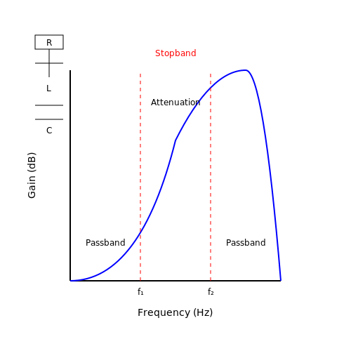
Applied band stop filters, also known as notch filters, are a specific type of electronic filter that attenuates or "stops" a particular band of frequencies while allowing frequencies outside this band to pass through. The primary function of these filters is to eliminate unwanted signals or noise within a specified frequency range, thus enhancing signal integrity in various applications.
The operational principle of band stop filters hinges on the selective interference of waveforms. By utilizing components such as resistors, capacitors, and inductors, engineers can create a circuit that resonates at the desired frequency range. This resonant behavior allows the filter to suppress signals while maintaining the amplitude and phase characteristics of the remaining frequencies.
Real-World Applications
Band stop filters are particularly valuable in a variety of contexts, including:
- Telecommunication: In communication systems, these filters are essential for eliminating interference from specific frequency bands, such as those caused by radio transmitters or electrical pulses that can corrupt data transmission.
- Audio Processing: In audio engineering, notch filters are used to remove hum and noise from signals, such as the 60 Hz power line noise common in many audio setups.
- Medical Devices: In medical instrumentation, applied band stop filters help filter out noise from equipment, enhancing the clarity of important signals derived from physiological measurements.
- Signal Processing: In radar systems, these filters help eliminate clutter from specific frequencies without impacting the radar's detection capabilities.
The design of an effective band stop filter requires a deep understanding of the desired frequency characteristics and the implications of the circuit's components on signal behavior. The filter's quality factor (Q-factor), for instance, is a crucial parameter that determines the breadth of the stop band. A higher Q-factor leads to a narrower stop band, making the filter more selective, though often at the cost of increased insertion loss outside this band.
In summary, the implementation of applied band stop filters is fundamental in engineering practices across numerous fields where precise signal control is necessary. By understanding the intricacies of these filters, engineers and researchers can design advanced systems that foster effective communication, clear audio reproduction, and accurate medical diagnostics.
1.2 Basic Concepts of Filtering
In the realm of applied electronics, the understanding and implementation of filters are paramount. Filters serve crucial roles in processing signals across a myriad of applications, from telecommunications to audio engineering, allowing desired signals to pass through while suppressing undesired frequencies. This section delves into the fundamental principles guiding filtering, focusing specifically on the nature of bandstop filters while underpinning their practical relevance. At its core, a filter can be characterized as a device or circuit that selectively allows or attenuates certain frequency components of a signal. The significance of filtering arises from the necessity to manage the frequency spectra effectively, a feature particularly crucial in systems where unwanted noise can distort the intended signal. The frequency response of filters is a critical metric. It describes how a filter reacts to the frequency components of a signal, expressed as the ratio of output signal amplitude to input signal amplitude over a range of frequencies. Understanding this concept enables engineers to tailor their designs to mitigate specific signal characteristics. Bandstop filters, also known as notch filters, are designed to reject signals within a specific frequency band while allowing frequencies outside this band to pass with minimal attenuation. This functionality is particularly relevant in scenarios such as radio communications, where specific frequencies may contain interference that could corrupt the desired transmission. To quantitatively describe filtering, we introduce the concept of the transfer function, represented as: $$ H(f) = \frac{Y(f)}{X(f)} $$ where \( Y(f) \) is the output signal, \( X(f) \) is the input signal, and \( H(f) \) characterizes the relationship between these signals in the frequency domain. As we delve deeper into filters, it is essential to explore the implications of filter design on system performance. Factors such as cutoff frequency, quality factor (Q), and roll-off profoundly influence the filter's effectiveness. The cutoff frequency defines the threshold at which the filter begins attenuating the input signal, while the quality factor determines the sharpness of this cutoff. A higher \( Q \) value signifies a narrower band of frequencies being attenuated. This interaction of parameters leads to a filter's bandwidth, which is the frequency range within which the output signal is significantly affected. Mathematically, it can be deduced as: $$ BW = f_{high} - f_{low} $$ where \( f_{low} \) and \( f_{high} \) define the lower and upper frequencies of the stop band, respectively. The design process of bandstop filters typically employs passive components (resistors, capacitors, and inductors) or active components (operational amplifiers) depending on the application requirements. A classic configuration for realizing a bandstop filter is the RLC circuit, illustrated in the accompanying diagram below. This configuration allows designers to effectively manipulate the filter's response characteristics by adjusting component values. Finally, practical implementations of bandstop filters are abundant across various industries, where they serve to eliminate specific interference frequencies in communication systems, audio signal processing, and even in medical devices to filter out noise from vital sign monitors. Mastery of filtering concepts empowers engineers and physicists to create robust systems that effectively manage signals under noisy conditions. Thus, an in-depth understanding of the basic principles of filtering, specifically in the context of bandstop filters, lays the groundwork for advancing in the domain of signal processing and applied electronics. Knowledge of filter design, performance parameters, and practical applications is essential for engineers and researchers striving to innovate in electronic systems and technologies.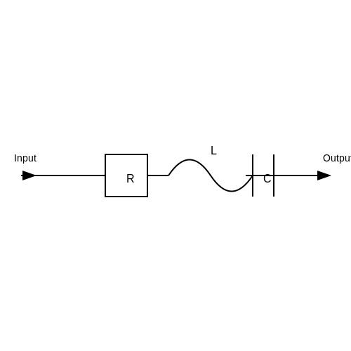
1.3 Types of Band Stop Filters
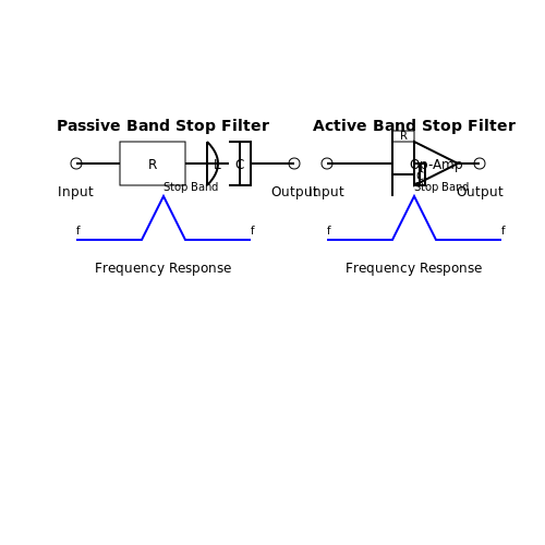
When exploring the versatile domain of band stop filters (BSFs), it's imperative to delineate the various types that have emerged through rigorous academic research and practical applications. Band stop filters, by design, effectively eliminate specific frequency ranges while allowing others to transit unimpeded. This characteristic makes them indispensable in fields such as telecommunications, audio engineering, and signal processing. Herein, we shall delve into the primary types of band stop filters: passive, active, and digital.Passive Band Stop Filters
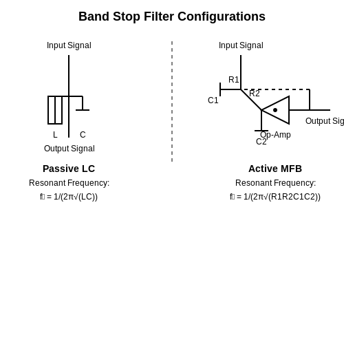
Passive band stop filters are predominantly constructed using passive components such as resistors, capacitors, and inductors. These filters are valued for their simplicity and efficacy in applications where signal amplification is not necessary, allowing for the selective attenuation of unwanted frequencies. To understand their operation, consider the common parallel LC circuit configuration, which employs a combination of inductors and capacitors. The resonant frequency \(f_0\) at which the circuit effectively blocks the input signals can be defined as:- Television tuners: to filter out interference from adjacent channels.
- Audio engineering: to eliminate hum from power lines at 60 Hz (or 50 Hz in some regions).
Active Band Stop Filters
Contrasting with passive filters, active band stop filters incorporate active components, such as operational amplifiers, to achieve signal amplification along with filtering. This addition not only allows for enhanced control over the filter's characteristics but also offers the possibility of greater selectivity and stability in output signals. One prevalent configuration is the multiple feedback (MFB) filter. This architecture typically employs two operational amplifiers, creating a more complex structure capable of sharper transitions between pass and stop bands. The transfer function of such an active band stop filter can be expressed in the form:- Control systems: to mitigate feedback oscillations at specific frequencies.
- Communication systems: to isolate noise from carrier signals.
Digital Band Stop Filters
The advent of digital signal processing has revolutionized the way band stop filters are implemented. Digital filters operate on discrete signals and employ algorithms to achieve filtering, allowing for unique capabilities and flexibility not available in analog counterparts. Digital band stop filters utilize techniques such as the Fast Fourier Transform (FFT) to efficiently analyze the frequency spectrum of signals. One commonly used approach is the design of a linear-phase finite impulse response (FIR) filter, which inherently maintains the waveform shape of signals. The design can be mathematically framed with windowed sinc functions to create a response that specifically targets the unwanted frequency band:- Audio processing: to remove electronic noise or specific frequency interference.
- Medical device signals: for instance, in ECG to eliminate power line interference.
2. Key Components: Resistors, Capacitors, and Inductors
2.1 Key Components: Resistors, Capacitors, and Inductors
The application of band stop filters is a common practice in various fields of electronics, particularly in signal processing where the removal of specific frequency bands is required. Understanding the key components utilized in creating these filters—resistors, capacitors, and inductors—is fundamental for designing effective filters tailored to specific applications.
Resistors: The Control Elements
Resistors are the basic components that provide resistance in a circuit, regulating the flow of current. They impact the filter's characteristics by determining its attenuation and stability. When constructing a band stop filter, resistors shape the frequency response and influence the bandwidth. Typically, they are used in conjunction with capacitors and inductors.
In practical applications, one must select resistors with appropriate power ratings to ensure they can handle the circuit's energy without degrading performance. The arrangement can be either series or parallel, modifying the resultant resistance based on Ohm's law:
Capacitors: The Frequency Dependent Components
Capacitors, which store electric energy, play a crucial role in enabling frequency selection in filters. Their impedance is frequency-dependent, described mathematically by the formula:
where \( Z_C \) is the capacitive impedance, \( j \) is the imaginary unit, \( \omega \) is the angular frequency, and \( C \) is the capacitance. In a band stop filter, capacitors are strategically used to block specific frequency ranges while allowing others to pass. Adjusting the capacitance value directly affects the filter characteristics, including its resonance frequency and quality factor, Q.
Inductors: The Magnetic Field Creators
Inductors are components that resist changes to current and store energy in a magnetic field. Their impedance is also frequency-dependent and can be expressed as:
where \( Z_L \) denotes the inductive impedance and \( L \) represents inductance. Just like capacitors, inductors play a vital role in defining the reactive nature of band stop filters. By using inductors, designers can create filters that effectively reject unwanted frequency ranges, often in conjunction with capacitors to create a notch filter or a multiple feedback band stop filter configuration.
Practical Applications
In various fields, the implementation of band stop filters is essential. For example, in audio engineering, removing unwanted hum frequencies from electric equipment enhances sound quality. Additionally, in wireless communications, band stop filters can mitigate interference from radio frequency signals, ensuring clearer transmission and reception. Furthermore, inductors and capacitors are integral in tuning and filtering applications for radio transmitters and receivers, preserving signal integrity.
In conclusion, a thorough understanding of resistors, capacitors, and inductors is critical when designing effective band stop filters. Their interactions enable engineers and researchers to tailor circuit responses, whether for industrial applications or sophisticated signal processing tasks.
2.2 Frequency Response Analysis
In the realm of applied band stop filters, understanding frequency response is essential, as it reveals how the filter reacts to different frequencies. A band stop filter, as the name implies, is designed to attenuate signals within a specific frequency range while allowing frequencies outside this band to pass relatively unimpeded. This inherent characteristic makes frequency response analysis a critical tool for evaluating the performance of such filters.Understanding Frequency Response
Frequency response is typically quantified in terms of gain and phase shift as functions of the frequency of the input signal. For a linear system, the frequency response can be characterized by its transfer function, \( H(f) \), which relates the output signal to the input signal in the frequency domain. The transfer function for an ideal band stop filter can be expressed as:Magnitude and Phase Response
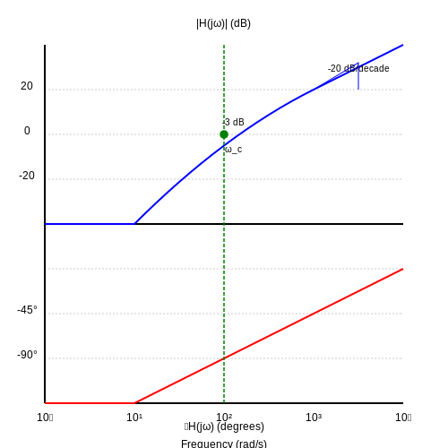
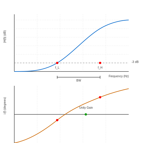
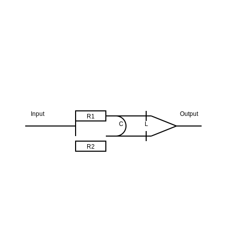
To analyze the practical aspects of frequency response, engineers often investigate both the magnitude and phase response of the filter. The magnitude response illustrates the extent to which the input signal is attenuated or amplified at various frequencies, while the phase response conveys the relative phase shift introduced by the filter. The magnitude response \( |H(f)| \) for a real band stop filter exhibits a characteristic dip between \( f_1 \) and \( f_2 \). This is typically plotted on a logarithmic scale to create a Bode plot, which allows for easier interpretation of the filter’s performance. The Bode plot displays the gain in decibels (dB) versus frequency on a logarithmic scale. The phase response \( \phi(f) \) can also be derived from the transfer function and is expressed as:Practical Relevance and Applications
Band stop filters are pivotal in numerous applications such as audio engineering, telecommunications, and instrumentation. Specifically, they can be utilized to eliminate unwanted frequency components. For instance, in audio systems, a band stop filter might be employed to attenuate hum or noise at 60 Hz, enhancing sound quality. In communication systems, such filters assist in eliminating narrowband interference, thereby improving the fidelity of the received signal. In control systems, band stop filters are essential for isolating specific signal frequencies, allowing engineers to focus on the relevant aspects of the system's response. Thus, understanding frequency response not only aids in the design of effective filters but also influences overall system performance. In summary, frequency response analysis is a vital aspect to grasp when working with band stop filters. It encompasses the transfer function, magnitude and phase responses, and their real-world implications in various engineering scenarios. Mastery of these concepts will not only enhance filter design capabilities but also strengthen the engineer's toolkit for tackling complex signal processing challenges.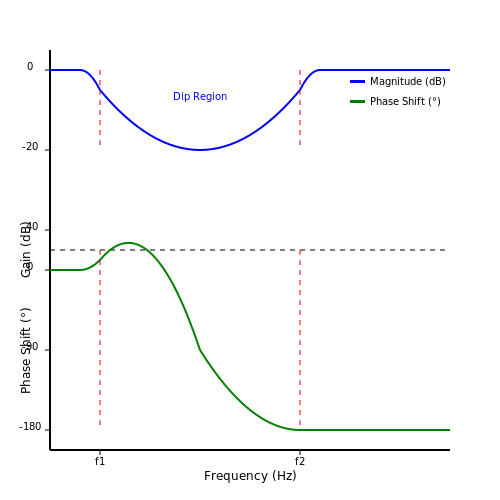
2.3 Quality Factor and Selectivity
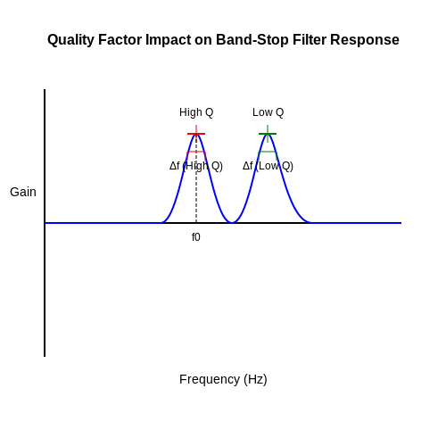
In the realm of applied band-stop filters, understanding the Quality Factor (Q) and Selectivity becomes paramount for engineers and researchers seeking to design circuits with precise response characteristics. The quality factor quantifies the bandwidth of the filter relative to its center frequency, providing crucial insight into how effectively a band-stop filter can attenuate unwanted signals while allowing desired frequencies to pass through.
The Quality Factor is defined as:
Here, \( f_0 \) represents the center frequency, and \( \Delta f \) is the bandwidth of the filter, defined as the difference between the upper and lower cutoff frequencies. A higher Q value indicates a narrower bandwidth, which means the filter is more selective and can better discriminate between adjacent frequency components. Conversely, a lower Q suggests a wider bandwidth, leading to potential interference from nearby frequencies.
The implications of the Quality Factor are extensive, especially in applications like audio processing, communication systems, and RF circuitry. For instance, in telecommunications, a band-stop filter with a high Q can effectively eliminate specific frequency bands associated with noise or interference, thereby enhancing signal integrity. Likewise, in audio equipment, these filters can be used to suppress unwanted frequency bands, such as those produced by electrical hum or digital noise.
Real-World Applications
To illustrate the practical significance of Quality Factor and Selectivity, we can evaluate their application in various systems:
- Telecommunication Systems: Filters with high selectivity prevent crosstalk between adjacent channels, promoting clearer communication.
- Audio Engineering: Band-stop filters selectively reduce specific frequencies, improving sound quality by removing distortions without affecting the overall signal.
- Medical Imaging: In MRI systems, selective filters are essential to reduce noise and enhance image quality, leading to better diagnostic capabilities.
High vs. Low Quality Factors
Choosing the right Quality Factor is often a trade-off:
- High Q filters produce a more pronounced notch but may cause phase shifts and lead to instability in feedback systems.
- Low Q filters provide greater bandwidth and stability but are less effective in filtering specific frequencies.
Understanding these nuances empowers engineers to tailor filter designs to meet the precise needs of their applications. In the upcoming sections, we will explore how to calculate these parameters quantitatively and design effective band-stop filters incorporating the principles of Quality Factor and Selectivity.
3. Use Cases in Audio Processing
3.1 Use Cases in Audio Processing
Within the realm of audio processing, applied band stop filters are introduced as powerful tools to mitigate specific frequency ranges that can interfere with sound clarity and quality. By selectively attenuating unwanted signals while preserving the desired components, these filters play a pivotal role in enhancing audio experiences.Noise Reduction in Music Production
One prominent application of band stop filters in audio processing is their effectiveness in noise reduction during music production. Background hiss, hum from electrical sources, and other unwanted frequencies can plague recordings. By implementing a band stop filter tuned to the offending frequency, typically around 60 Hz for electrical hum, sound engineers can significantly enhance the audio quality without compromising the integrity of the musical content. The design of these filters is predominantly influenced by the quality factor (Q) and the center frequency. A higher Q indicates a narrower band of frequencies being attenuated, which is often ideal for isolating persistent noise while leaving the rest of the audio spectrum intact. Understanding this balance is crucial for sound engineers to ensure that they do not inadvertently affect the musical notes that reside close to the targeted frequencies.Speech Clarity in Communication Systems
In voice communication systems, band stop filters are also frequently employed to improve speech clarity. Disruptive low-frequency noise can often obscure spoken words, making clear communication challenging. By strategically placing a band stop filter in the audio signal chain around the low-frequency noise (e.g., below 100 Hz), systems can boost the intelligibility of speech in crowded environments. Additionally, such filters can be implemented in telecommunication systems to diminish feedback loops and enhance the overall fidelity of the audio signal. This has practical applications across telephony, video conferencing, and any communication requiring clear voice transmission.Feedback Elimination in Live Sound Systems
For live sound engineers, feedback is a common adversary that can compromise audio quality. Here, advanced band stop filters are integrated into equalization systems to identify and eliminate feedback frequencies, particularly around 1 kHz to 4 kHz, where feedback tends to be most prominent. By monitoring the audio output through real-time analysis, such filters can dynamically adapt to changing sound fields and retain optimal sound quality for audiences. The implementation of band stop filters for feedback control has proven to be invaluable in larger venues, ensuring that performances maintain their sonic integrity without the interruption or distraction of screeching feedback.Implementation in Digital Audio Workstations (DAWs)
In the realm of digital audio workstations, the virtual representation of band stop filters allows for precise adjustments in post-production. Musicians and sound designers can apply these filters using plugins to eliminate undesired frequencies after the recording phase. They offer visual interfaces that provide real-time feedback, making it easy to analyze the signal and determine the optimal settings for the filter based on the specific needs of the track. With the increasing complexity of modern audio processing tools, the accessibility of band stop filters has markedly enhanced the creative capabilities of sound engineers. This application extends to multimedia projects where sound design needs to complement visual elements without troubling frequencies interfering with the overall experience. In conclusion, applied band stop filters occupy a critical niche in audio processing, addressing a spectrum of noise-related challenges from music production to live performance environments. Mastering their application is essential for professionals who aim to ensure that audio signals remain clear, intelligible, and free from unwanted interference. As technology continues to evolve, so will the sophistication with which these filters are implemented, thereby enhancing audio quality even further.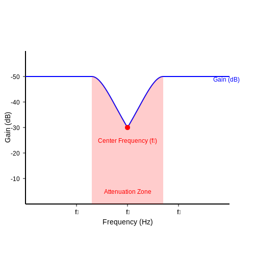
3.2 Applications in Communication Systems
In the field of communication systems, applied band stop filters serve as crucial components for enhancing signal clarity and integrity. These filters are specifically designed to attenuate particular frequency bands while allowing frequencies outside the stopband to pass with minimal loss. The practical applications of band stop filters span various communication technologies, from wireless systems to complex signal processing techniques. The main purpose of utilizing band stop filters in communication systems is to eliminate interference from unwanted frequency components. Such interference can arise from numerous sources, including electromagnetic interference (EMI), co-channel interference, and even cellular activity, all of which can adversely affect the performance of a communication system.Signal Processing and Noise Reduction
One of the most significant applications of band stop filters is in the realm of signal processing. Here, they are primarily employed to mitigate the effects of noise that fall within specific frequency ranges. For instance, in wireless communication, certain frequency bands may be prone to interference from devices operating within those same ranges. By implementing a band stop filter, engineers can selectively suppress these frequencies, enhancing the overall signal-to-noise ratio (SNR). A classical example is the suppression of 50/60 Hz noise in power line communication systems. Band stop filters can effectively reduce this noise, allowing for clearer data transmission over power lines without the distortion caused by electrical interference. In a typical design, the filter can be modeled as an RLC circuit configuration, where the resonant frequency is tuned to precisely target the interference frequency. Strong emphasis is placed on the filter's quality factor (Q), which determines the sharpness of the stopband. A higher Q factor produces a steeper roll-off, leading to more effective attenuation of the unwanted frequencies. The relationship can be expressed mathematically in the following manner:Wireless Communication Networks
In wireless networks, particularly in the design of antennas and transceiver systems, band stop filters play an essential role. They are used to prevent signal degradation caused by out-of-band emissions from nearby transmitters. For example, commercial wireless communication devices often use band stop filters to filter out signals from adjacent bands that could mask or interfere with the intended transmission. Consider the case of mobile communication systems operating within the GSM band (900 MHz). Here, band stop filters can strategically attenuate frequencies utilized by other services, such as Wi-Fi (2.4 GHz) or LTE (1.8 GHz), ensuring that the performance of devices within the GSM band remains optimal. This application highlights the necessity of designing filters that can be finely tuned to accommodate varying standards and requirements across different frequency bands.Case Study: GPS Frequency Interference
A practical illustration of band stop filter application can be seen in GPS systems, where they are implemented to mitigate interference from intentional or unintentional sources. For instance, an experimental setup recently deployed in urban areas showed that GPS signals at 1.575 GHz were subject to interference from local broadcast transmissions. By integrating a band stop filter, researchers were able to achieve improved positional accuracy and reliability, affirming the critical role of such filters in modern technologies. In summary, applied band stop filters are indispensable components within communication systems, addressing interference challenges and enhancing signal integrity. As technology evolves, the significance of these filters will likely grow, facilitating advancements in wireless communication and broader signal processing applications. With ongoing research and development, the design parameters of these filters, including their efficiency, bandwidth characteristics, and integration methodologies, will continue to adapt to meet the demands of ever-increasing signal complexity in our interconnected world.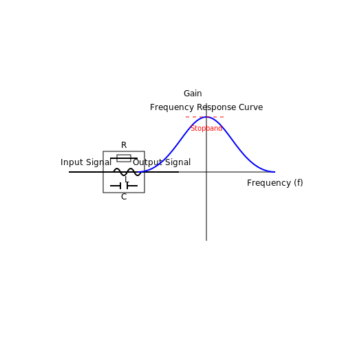
3.3 Integration with Other Electronics
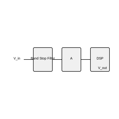
To effectively utilize band stop filters in practical applications, understanding how they can be integrated with other electronic components is essential. This integration not only enhances the performance of electronic systems but also allows for greater versatility in signal processing, enabling engineers to design robust systems with minimized interference. One of the primary uses of band stop filters is in communication systems, where they serve to eliminate specific unwanted frequencies that may interfere with the designated signal bandwidth. For instance, consider a radio transmitter that operates within a certain frequency band. When a band stop filter is employed, it can effectively attenuate nearby channels, thereby reducing noise and improving the overall clarity of the signal being transmitted. Moreover, the integration of band stop filters with amplifiers is a common practice. In many devices, signals are amplified before they are transmitted, and incorporating a band stop filter before the amplifier helps prevent amplification of undesired frequencies. This coupling ensures that the amplifier operates more efficiently by focusing on the desired frequency range, which can lead to improved system performance. The basic configuration can be summarized in the following circuit arrangement:In an integrated circuit context, band stop filters can also be realized using various technologies, including passive RC (resistor-capacitor) networks or active filters using operational amplifiers. The choice depends on the application requirements such as bandwidth, insertion loss, and power consumption.
When integrating band stop filters into complex systems, it is vital to consider their interaction with digital signal processing (DSP) units. DSPs are capable of adaptive filtering, where the filter characteristics can adjust dynamically to changing signal conditions. This contrasts with traditional band stop filters that have fixed parameters; however, by using programmable band stop filters in conjunction with DSP systems, one can achieve a higher level of tuning to specific applications, such as in audio processing where certain frequencies (like hum) need to be suppressed. In practice, a noise suppression module might consist of a band stop filter, followed by a DSP microcontroller, which continually analyzes the incoming signal. As the DSP processes the audio signal, it can make real-time adjustments to the filter parameters based on the detected noise levels, thereby dynamically reshaping the filter’s performance.In conclusion, the modular integration of band stop filters with other electronic components serves as a cornerstone for advanced signal processing techniques in modern electronic systems. As technology continues to evolve, embracing the interplay between filters, amplifiers, and DSPs will provide engineers with the tools necessary to enhance performance and achieve greater efficiency in their designs.
4. Circuit Simulation Tools
4.1 Circuit Simulation Tools
In the design and analysis of applied band-stop filters, circuit simulation tools play a crucial role. These tools enable engineers and researchers to visualize and validate the behavior of filters under various conditions before hardware implementation. By providing a virtual environment where parameters can be adjusted and results can be quickly assessed, simulation tools enhance efficiency and accuracy in the design process.
Modern simulation software, such as SPICE (Simulation Program with Integrated Circuit Emphasis), allows users to create detailed models of electronic circuits. SPICE is instrumental for analyzing linear and nonlinear circuits, providing insights into frequency response, stability, and component interactions. A band-stop filter, designed to attenuate specific frequencies while allowing others to pass, is an excellent application of such tools.
Types of Circuit Simulation Tools
There are several types of simulation tools available, categorically differentiated by their functionality and complexity:
- SPICE-based simulators: These include LTspice, PSpice, and HSPICE, which are fundamental for transistor-level simulations. They support a wide variety of component models, making them ideal for band-stop filter analysis.
- Frequency domain simulators: Tools like MATLAB and Mathematica allow users to perform frequency response analyses. These platforms are particularly useful for designing and tuning filters, enabling engineers to visualize magnitude and phase responses interactively.
- RF and microwave simulation tools: Software such as ADS (Advanced Design System) and HFSS (High-Frequency Structure Simulator) offer specialized features for RF applications. They include electromagnetic simulation to accommodate circuit layout effects at high frequencies.
Importance of Accurate Modeling
Accurate modeling within these simulation environments allows users to achieve a more profound understanding of circuit behavior, reducing the need for iterative physical prototyping. When designing a band-stop filter, for instance, one can visualize how component variations—like resistor or capacitor tolerances—impact the attenuation of undesired frequencies. This insight is invaluable in applications such as telecommunications, audio processing, and signal integrity within digital systems.
Typically, a circuit simulation starts with defining a schematic. For a band-stop filter, which can be created using various topological configurations like passive RC filters or active configurations involving op-amps, accurately defining component values is key. The simulation would then allow the user to analyze the transfer function, revealing how the output signal is influenced by various input frequencies.
Example: Simulation of a Simple RC Band-Stop Filter
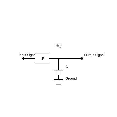
Consider the design of a basic band-stop filter using a resistor-capacitor (RC) network. The transfer function \( H(f) \) can be derived using voltage divider principles, where the characteristic frequencies that are attenuated depend on the values of the resistors \( R \) and capacitors \( C \).
Here, \( f_0 \) represents the center frequency of the attenuation band. By simulating this filter, one can observe its frequency response and adjust \( R \) and \( C \) accordingly to optimize performance for specific applications.
Finally, the integration of simulation tools into the design workflow not only expedites the development process but also enhances the reliability of finished products. Engineers can rigorously test designs through advanced functionalities, such as Monte Carlo analysis for statistical variations and sensitivity analysis, ensuring comprehensive performance assessments.
This foundational understanding of simulation tools will set the stage for practical applications within the field of applied band-stop filters, leading to more efficient designs and robust electrical systems.
4.2 Real-World Testing and Measurements
To fully appreciate the effectiveness of applied band stop filters, it's crucial to engage in practical testing and measurement. This process allows engineers and researchers to validate theoretical models and to ensure that the filters perform as expected in real-world conditions.Understanding the Importance of Real-World Testing
In theory, a band stop filter is designed to attenuate signals within a specified frequency range while allowing others to pass through. However, various factors such as component tolerances, parasitic capacitances, and inductances can influence the filter's actual performance. Real-world testing helps identify these discrepancies and fine-tune the design to meet desired specifications.Measurement Techniques and Tools
To test band stop filters, several measurement techniques and tools are commonly utilized:- Vector Network Analyzers (VNAs): Essential for characterizing the frequency response of filters, VNAs can provide information about insertion loss and return loss across a specified frequency span.
- Signal Generators: These devices produce signals at various frequencies, which can be fed into the filter for performance evaluation.
- Oscilloscopes: Used to visualize the output waveform, oscilloscopes can confirm that the filter operates correctly by showing the attenuation of undesired frequencies.
- Power Meters: Useful for measuring actual power loss through the filter, thus helping to quantify its performance.
Example Case Study: Testing a Practical Band Stop Filter
Consider the case study of designing a band stop filter intended to eliminate interference at 50 MHz, a common frequency used in wireless communication systems. The design of the filter might involve a combination of passive components such as resistors, capacitors, and inductors. A typical configuration for a second-order LC band stop filter is shown below, where \(L\) is the inductance and \(C\) is the capacitance:Common Challenges in Real-World Measurement
While testing reveals valuable insights, common challenges can arise: - Environmental Factors: Temperature and humidity can alter component behavior. - Interference: Nearby electronic devices can introduce noise, skewing results. - Component Variability: Real-life components often deviate slightly from their nominal values due to manufacturing tolerances. Understanding these challenges allows researchers and engineers to develop strategies to minimize their impact, ensuring more accurate results.Future Directions in Band Stop Filter Testing
Innovations in measurement technology offer exciting prospects for future testing methodologies. For example, the integration of software-defined radio (SDR) systems can enhance testing capabilities, allowing for extensive analyses in diverse environments. This will not only deliver a deeper understanding of filter performance but also streamline the process of designing and calibrating band stop filters for industry applications. Through rigorous testing and validation, the performance of band stop filters can be accurately characterized, paving the way for advancements in communications, signal processing, and various electronic applications.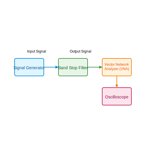
4.3 Troubleshooting Common Issues
In the application of band stop filters, it is not uncommon to encounter challenges that can hinder optimal performance. Understanding the underlying causes of these issues is crucial for engineers and researchers working in fields such as telecommunications, audio processing, and signal analysis. This section outlines common problems, their manifestations, and strategies for effective troubleshooting.Understanding the Nature of Band Stop Filter Issues
Band stop filters are designed to attenuate a specific range of frequencies while allowing others to pass through. However, ideal behavior often eludes practical implementations. Problems may arise from component quality, circuit design, or incorrect tuning. Recognizing the symptoms of these issues is the first step toward effective troubleshooting.Common Issues and Solutions
1. Incorrect Cutoff Frequency: A prevalent issue is misalignment of the intended cutoff frequency. This could stem from incorrect component values, particularly the capacitors and inductors in an RLC circuit. To verify the cutoff frequency ($$f_c$$), we can use the formula derived from a standard second-order band stop filter:Practical Troubleshooting Techniques
A systematic approach to troubleshooting may include the following steps:- Simulation Tools: Use circuit simulation software such as SPICE to test hypothetical scenarios before physical implementations.
- Component Testing: Employ an LCR meter to validate component values, ensuring they meet design specifications.
- Frequency Response Analysis: Utilize a signal generator and an oscilloscope to observe the frequency response of the filter, comparing theoretical and actual behaviors.
- Temperature Effects: Recognize that environmental factors can affect component behavior. Perform tests under various temperature conditions to ensure consistency.
Real-World Applications and Importance
Troubleshooting band stop filters extends beyond mere circuit adjustments; it can have significant impacts on system performance in applications such as radio frequency (RF) communications, where precision filtering is necessary to avoid interference and maintain signal integrity. Effective addressing of these common issues ensures that systems operate as intended, improving reliability and efficiency. By employing both theoretical insights and practical troubleshooting skills, engineers and researchers can better manage the complexities involved in designing and implementing band stop filters, paving the way for advancements in electronic and signal processing technologies.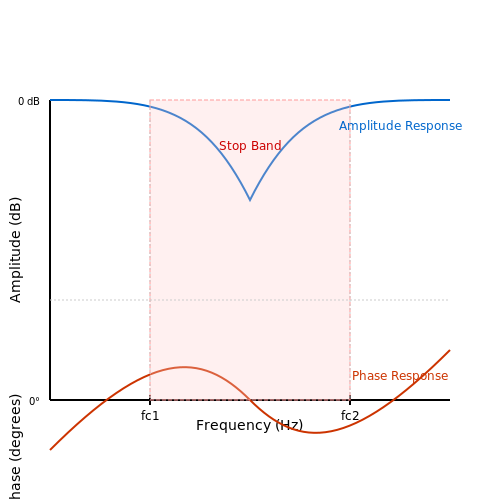
5. Active vs. Passive Band Stop Filters
5.1 Active vs. Passive Band Stop Filters
Introduction to Band Stop Filters
Band stop filters (BSFs) play a crucial role in signal processing, essentially acting to attenuate (or "stop") signals within a specific frequency range while allowing others to pass through unaffected. Understanding the differences between active and passive implementations of these filters is fundamental for engineers and researchers developing advanced electronic systems.
Passive Band Stop Filters
Passive band stop filters are composed solely of passive components—namely resistors, capacitors, and inductors. The simplicity of this design translates into several advantages:
- No external power supply required: This enhances reliability and reduces complexity in circuit design.
- Low cost: The absence of active components keeps material costs down, making passive filters ideal for basic applications.
- Linear characteristics: Passive filters inherently possess linear frequency response, which can be predictable and manageable for stable applications.
Typically, a classic design for a passive band stop filter employs an RLC circuit configuration where resistive and reactive components are arranged to create a notch in the frequency response. The cutoff frequencies, defined as the boundaries of the stopped band, can be calculated using the following relations:
where fc represents the cutoff frequency, L is inductance, and C is capacitance. This equation allows designers to manipulate component values to achieve desired frequency characteristics.
Active Band Stop Filters
In contrast, active band stop filters incorporate active components such as operational amplifiers (op-amps), which introduce amplification that allows more sophisticated behavior:
- Increased flexibility: Active filters can easily achieve sharper roll-off characteristics and a deeper attenuation within the stopband due to feedback and gain control.
- Impedance buffering: Active filters can buffer input and output signals, making them less sensitive to variations in the load impedance, which is a crucial advantage in complex signal environments.
- Voltage gain: The integration of op-amps grants the ability to not only filter the signal but also amplify it, which can be particularly useful in applications where signal strength needs to be preserved after filtering.
The design of an active band stop filter usually involves configuring an op-amp in a differential or Sallen-Key configuration, allowing for precise control of the center frequency and bandwidth. The formula for the center frequency in an active band stop filter can be expressed as:
Here, f0 is the center frequency, R1 and R2 are resistances, while C1 and C2 are capacitances defining the frequency response.
Comparative Insights and Applications
The choice between active and passive band stop filters largely depends on the specific requirements of the application, encompassing performance, components, and design constraints:
- Applications requiring high precision: Active filters tend to be preferred in modern telecommunication systems, audio processing, and instrumentation due to their superior control over characteristics of the filter.
- Low-power and cost-sensitive applications: Passive filters find their use in applications where power consumption is critical, such as in portable devices.
- Signal integrity: Active filters help maintain signal integrity in high-frequency applications where the influence of external loads is a concern.
Ultimately, understanding the trade-offs between active and passive configurations of band stop filters empowers engineers to design systems that meet performance expectations while balancing flexibility and practical considerations.
5.2 Digital Implementations
As technology advances, the methodologies used to implement band stop filters (BSFs) have increasingly transitioned from analog to digital domains. This shift not only enhances the design's flexibility but also allows for greater precision and adaptability in performance characteristics. In this section, we will explore the digital implementation of band stop filters, addressing their theoretical underpinnings, common approaches, and real-world applications.Understanding Digital Band Stop Filters
Digital band stop filters are integral components in various signal processing applications, such as audio processing, telecommunications, and biomedical engineering. They are utilized to eliminate or attenuate specific unwanted frequency ranges within a digital signal while allowing others to pass unaffected. This capability is critical in environments where noise or interference can degrade signal quality. The fundamental difference between analog and digital BSFs lies in the representation of signals and the processing algorithms used. Digital filters operate on discrete data using mathematical operations rather than continuous voltage levels.Common Digital Filter Design Techniques
There are several prevalent techniques for designing digital band stop filters. Among these, the three most common approaches include:- Finite Impulse Response (FIR) Filters: FIR filters are characterized by a finite number of non-zero coefficients. They are inherently stable and have a linear phase response, making them ideal for applications requiring minimal phase distortion. The coefficients can be designed using methods such as the windowing technique, the Parks-McClellan algorithm, or frequency sampling.
- Infinite Impulse Response (IIR) Filters: Unlike FIR filters, IIR filters have feedback elements, which allow them to achieve a desired frequency response with fewer coefficients. This makes IIR filters efficient but can lead to stability issues. The bilinear transformation method is often employed to design IIR filters, alongside the Butterworth and Chebyshev prototype filters.
- Wavelet Transform: An emerging technique in digital signal processing, wavelet transforms allow for time-frequency analysis, enabling the design of filters that can adapt based on the signal characteristics. This method can effectively target specific frequency bands for filtration while preserving important temporal information.
Mathematical Foundation
To derive the digital filter equations, it is crucial to understand their mathematical foundation. We can consider a simple FIR filter as an example. The output signal \( y[n] \) is determined by convolving the input signal \( x[n] \) with the filter coefficients \( b[k] \): $$ y[n] = \sum_{k=0}^{M} b[k] x[n-k] $$ Where: - \( M \) is the order of the filter. - \( b[k] \) represents the filter coefficients. The design of the coefficients \( b[k] \) is influenced by the desired frequency response, which can be crafted using the methods mentioned earlier. For a band stop filter targeting frequencies \( f_1 \) and \( f_2 \), the magnitude response \( |H(e^{j\omega})| \) would ideally approach zero in the frequency range between \( f_1 \) and \( f_2 \): $$ |H(e^{j\omega})| = \begin{cases} 1 & \text{for } \omega < \omega_1 \text{ or } \omega > \omega_2 \\ 0 & \text{for } \omega_1 \leq \omega \leq \omega_2. \end{cases} $$ This leads to a direct relationship between the time-domain coefficients and the frequency-domain performance.Real-World Applications
The practical relevance of digital band stop filters is seen in various domains: 1. Audio Engineering: In music production, specific frequencies, such as hum from electrical sources (often at 50/60 Hz), are targeted for removal to enhance sound quality. 2. Telecommunications: Band stop filters are essential in communication systems to mitigate interference from signals like FM radio channels in modern digital communication protocols. 3. Biomedical Signal Processing: In medical applications, digital BSFs help remove artifacts from signals, such as electrocardiograms, ensuring clearer data for diagnostics. As digital signal processing continues to advance, the development of adaptive and intelligent band stop filters will offer significant opportunities for improving the fidelity and integrity of signal transmission across various platforms.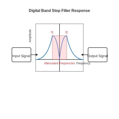
5.3 Emerging Technologies and Future Trends
The field of applied band stop filters (BSFs) has seen remarkable advancements in recent years, driven by the convergence of innovations in materials science, microelectronics, and signal processing techniques. In this subsection, we will explore some of the most significant emerging technologies and future trends that promise to reshape the way we utilize and implement band stop filters in various applications.Advancements in Materials and Fabrication Techniques
The evolution of materials has been pivotal in creating more efficient and effective band stop filters. Traditional passive components like inductors and capacitors have limitations regarding miniaturization, loss, and thermal stability. However, new materials such as metamaterials and nanostructured composites enable enhanced control over electromagnetic responses. Metamaterials, composed of engineered structures rather than conventional substances, have properties that can be tailored to specific frequencies. By designing these materials at the microscopic level, engineers can create filters with a high degree of selectivity and attenuation, even at small physical sizes. This is crucial for applications in telecommunications where space is at a premium. Furthermore, the development of additive manufacturing techniques, like 3D printing, allows for the rapid prototyping of complex filter designs. By combining different materials and geometries, designers can create customized filters that are not only lightweight and compact but also capable of operating over a range of frequencies.Integration with Advanced Signal Processing
Modern electronic systems increasingly utilize digital signal processing (DSP) techniques. By integrating band stop filters with sophisticated DSP algorithms, engineers can achieve dynamic filtering capabilities that were previously unfeasible. Such integration allows for adjustable filter characteristics that can adapt to varying signal conditions in real-time. For instance, in audio applications, adaptive filters can automatically suppress unwanted frequencies (like hum or noise) while maintaining the integrity of the desired signal. This adaptability not only enhances audio quality but is also applicable in communications where signal integrity is paramount in noisy environments. Moreover, the shift towards software-defined networking (SDN) requires flexible filtering solutions that can be quickly reconfigured via software. Band stop filters that can be adjusted or programmed digitally offer the agility and versatility needed in modern communication infrastructures.Sustainability and Energy Efficiency
In the wake of increasing environmental concerns, the demand for energy-efficient electronic components is a significant trend. The focus on sustainability extends to the design and operation of band stop filters as well. Using low-loss materials and innovative designs can reduce the power consumption of filters, making them more sustainable. One key area of research involves the development of passive filters that do not only exhibit reduced loss but also can be constructed from recyclable materials. This aligns with the growing push toward a circular economy in electronics where components are designed to minimize waste and maximize lifecycle sustainability. Moreover, advancements in energy harvesting technologies can complement band stop filters in sensor networks. These filters can play a crucial role in mitigating interference in signals that energy-harvesting devices produce, thus enabling their wider deployment in IoT applications.Wearable Technologies and Biomedical Applications
The proliferation of wearable technology necessitates innovative solutions in signal processing and filtering. Band stop filters are vital in biomedical telemetry, where they help eliminate noise from biological signals such as ECG or EEG, enabling clearer data collection for diagnostics and health monitoring. Emerging wearable health devices leverage advanced BSF designs to ensure that the integrity of critical health signals is maintained while rejecting unwanted frequencies associated with motion artifacts or electromagnetic interference. This holds affirmatively for the development of non-invasive medical devices that require high fidelity in the signal reception. As wearable devices become more advanced and pervasive, the implementation of miniature, low-profile band stop filters will play a crucial role in ensuring data monitors retain accuracy and reliability, thereby enhancing patient outcomes and facilitating continuous health tracking.Conclusion
As we look to the future, the integration of emerging technologies and innovative approaches will continue to redefine the capabilities of applied band stop filters. From material science advancements to sustainable practices and digital signal processing innovations, these trends promise to enhance the performance and applicability of BSFs across numerous fields, ranging from telecommunications to biomedical applications. By harnessing these capabilities, engineers and researchers can develop the next generation of filtering technology that aligns with evolving industry demands and societal needs.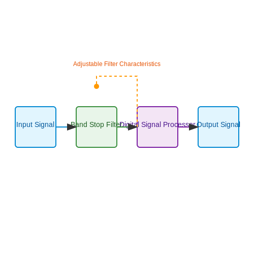
6. Recommended Textbooks
6.1 Recommended Textbooks
- Analysis and Design of Analog Integrated Circuits — Authored by Paul R. Gray, this textbook is a comprehensive resource on analog circuit design. It covers the intricate details of analog signals including filters like Band Stop filters, making it ideal for advanced study.
- Theory and Application of Digital Signal Processing — This classic book by Lawrence R. Rabiner and Bernard Gold deeply explores digital signal processing concepts, including filter design and applications, essential for understanding applied band stop filters in a digital context.
- Electric Circuits — Written by James W. Nilsson and Susan A. Riedel, this text provides foundational knowledge on electric circuits, with relevant sections on analog filters that support advanced studies on band stop implementations.
- Fundamentals of Electric Circuits — Charles K. Alexander and Matthew N.O. Sadiku's book is a staple in understanding the essentials of electric circuits and filtering techniques, invaluable for designing and understanding band stop filters.
- Bandpass Filters for RF and Microwave Communications — Although focused more on bandpass filters, this text by Pierre Jarry and Jacques Beneat offers insights into advanced filter design useful for comprehending the broader category of band stop filters as well.
- Microelectronic Circuit Design — Authors Richard C. Jaeger and Travis N. Blalock provide deep insights into microelectronic systems, including the design and application of various filters, suitable for advanced learning about band stop filters.
- Digital Signal Processing: Principles, Algorithms, and Applications — John G. Proakis and Dimitris K. Manolakis dive into digital signal processing with applicable filter design techniques, offering a deep understanding of band stop filters in the digital domain.
- Design of Analog Filters — This book by Rolf Schaumann and Mac Van Valkenburg offers an exploration of filter design theory and practice, necessary for mastering band stop filter concepts at a professional engineering level.
6.2 Online Resources and Tutorials
As the field of electronics continues to evolve, staying updated with the latest research and methodologies is crucial for advanced practitioners. This section provides a curated list of online resources and tutorials, specifically targeting band stop filters, a critical component in signal processing. These resources are invaluable for professionals seeking to deepen their knowledge and application of band stop filters in various domains, from telecommunications to audio engineering.
- All About Circuits - Band Stop Filters — Offers a comprehensive explanation of band stop filters, including their theory, equations, and practical examples, essential for deepening theoretical understanding and practical skills.
- Electronics Tutorials - Band Stop Filter — Provides detailed discussions on the types, designs, and applications of band stop filters, suitable for advanced-level users interested in complex circuit designs.
- YouTube - Designing Band Stop Filters — A video tutorial focusing on practical design and simulation of band stop filters for real-world applications, ideal for visual learners.
- Texas Instruments - Application Report on Band Stop Filters — An in-depth application report by Texas Instruments exploring integrated band stop filter solutions with a focus on modern electronics applications.
- Analog Dialogue - Design of Band Stop Filter — This article by Analog Devices provides advanced design techniques and considerations for band stop filters in signal processing applications.
- IEEE Xplore - Research Papers on Band Stop Filters — A vast repository of peer-reviewed research papers, offering cutting-edge insights and studies on the development and application of band stop filters.
- Coursera - Analog Electronics Course — This comprehensive course includes modules on filter design and implementation, catering to professionals interested in hands-on and in-depth learning.
These resources provide both foundational knowledge and advanced insights into band stop filters, ensuring that readers can effectively apply these components in complex circuit designs and innovative applications.
6.3 Academic Journals and Papers
- ScienceDirect: Design and Optimization of Band Stop Filters — A comprehensive article discussing the design techniques and optimization strategies for band stop filters in electronic applications.
- IEEE Xplore: Ultra-Wideband Band Stop Filters Research — An in-depth study on the development of ultra-wideband band stop filters, covering both theoretical approaches and experimental results.
- IEEE Xplore: Novel Band Stop Filter Design Using Metamaterials — This paper presents innovative designs of band stop filters using metamaterials to achieve unique filtering properties.
- MDPI Electronics: Advances in Compact Band Stop Filters — This article reviews recent advancements in constructing compact band stop filters and their applications in modern electronics.
- SAGE Journals: Band Stop Filters for Interference Mitigation — Discusses the role of band stop filters in mitigating interference in communication systems, emphasizing case studies and real-world applications.
- SAGE Journals: Historical Developments in Filter Technology — Provides a historical analysis of the evolution of filter technology, with a focus on the development of band stop filters.
- IET Radar, Sonar & Navigation: Impact of Band Stop Filters on Radar Technology — Explores the utilization of band stop filters in enhancing radar systems' performance, analyzing both theoretical insights and practical implementations.