Current Feedback Amplifiers
1. Definition and Importance
1.1 Definition and Importance
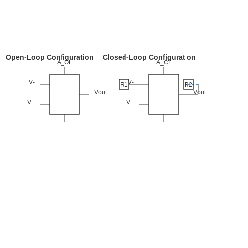
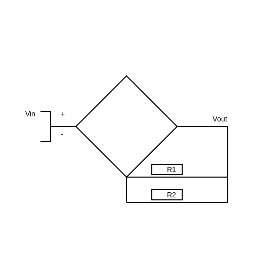
Current feedback amplifiers (CFAs) represent an important class of analog amplifiers designed for high performance, particularly in applications demanding low distortion and wide bandwidth. Unlike traditional voltage feedback amplifiers, CFAs utilize current feedback, which leads to a fundamentally different operational mechanism, and thus are capable of achieving superior performance specifications in many scenarios. The essence of a CFA is captured in its unique configuration; it directly employs the feedback current instead of the output voltage to control its gain. This configuration allows for greater flexibility in bandwidth and linearity over a broader range of frequencies. To elucidate, a conventional voltage feedback amplifier achieves stability and bandwidth through the manipulation of voltage levels. In contrast, a CFA adjusts its operation by varying the feedback current, resulting in a more stable gain across a wide operating range. This is especially beneficial for applications such as video processing, instrumentation, and any high-frequency signal amplification. To understand the relevance of CFAs in a more concrete manner, consider their application in operational amplifiers within audio signal processing. In high-fidelity systems, where clarity and distortion-free transmission of audio signals are critical, CFAs help ensure that the audio quality remains pristine, even at high volumes, due to their ability to maintain linearity and minimize phase shifts. This capability is crucial when designing audio equipment, as it ensures that amplifiers reproduce sounds as closely as possible to the original recording. Another aspect worth noting is the implementation of CFAs in the realm of photodetector interfaces. Photodetectors, such as photodiodes, exhibit low output levels, necessitating effective amplification for signal processing. CFAs are ideal in such scenarios due to their low input impedance, which matches well with photodetector characteristics, ensuring efficient signal transfer without significant loss. With this backdrop, we can delve deeper into the operational mechanics of CFAs and appreciate their architectural nuances. This exploration begins with the basic architecture of a current feedback amplifier — typically comprising an operational amplifier with two active components: a transistor and a feedback resistor, and a loop that interconnects output with the inverting input via a feedback path. The advantage of this architecture becomes clear when we examine the frequency response of CFAs. Unlike traditional amplifiers that experience gain roll-off at higher frequencies, CFAs can maintain a consistent gain due to their unique feedback characteristics. In the upcoming sections, we will derive the fundamental equations governing the function of CFAs, allowing for a deeper understanding of how these amplifiers operate under different conditions and in various applications. We will also discuss their limitations and how these might be addressed through careful circuit design and advanced materials, solidifying CFAs' place in modern electronic design.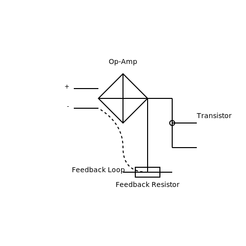
1.2 Basic Principles of Operation
Current feedback amplifiers (CFAs) represent an innovative class of operational amplifiers characterized by their unique feedback mechanisms. Unlike traditional voltage feedback amplifiers that primarily depend on voltage feedback for performance, CFAs utilize feedback in the current domain, leading to several distinct advantages, particularly in speed and bandwidth.
To appreciate how a current feedback amplifier operates, we need to first explore the underlying principles of feedback in electronic circuits. In any amplifier, feedback is a critical mechanism by which part of the output signal is returned to the input, influencing performance characteristics such as gain, stability, and linearity. In CFAs, feedback is applied through the current path rather than the voltage path, enabling high-speed operation.
Operational Mechanism
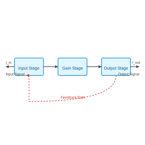
A standard CFA is composed of an input stage, a gain stage, and an output stage. At its core, the principle of operation lies in the interaction of these stages combined with the feedback network. The input signal is fed into the amplifier, where it is processed by the gain stage. The output from this stage is then fed back into the input, influencing the amplification process based on the current rather than voltage.
The mathematical foundation governing this behavior can be expressed as follows:
where:
- $$I_{out}$$ is the output current.
- $$A$$ is the amplifier's gain.
- $$I_{in}$$ is the input current.
Advantages of Current Feedback
The current feedback method presents several compelling advantages:
- Increased Bandwidth: CFAs can achieve higher bandwidths compared to their voltage feedback counterparts, often making them suitable for high-frequency applications.
- Enhanced Slew Rate: The slew rate, or the speed at which an amplifier can respond to changes in the input signal, is significantly improved in CFAs due to current feedback, allowing for faster signal processing.
- Lower Distortion: The inherent feedback characteristics result in reduced distortion and improved linearity, making them ideal for high-fidelity applications.
Real-World Applications
The unique operating principles of CFAs make them particularly valuable in various real-world applications. For instance, they are commonly employed in:
- Audio Processing: CFAs are actuated in high-end audio amplifiers where fidelity and speed are crucial.
- Telecommunication Systems: The ability of CFAs to handle rapidly changing signals makes them suitable for RF amplifiers and other communication devices.
- Signal Conditioning: These amplifiers improve signal integrity in sensor systems and other data acquisition applications.
As the field of electronics continues to evolve, understanding the basic principles governing current feedback amplifiers becomes paramount for engineers and researchers seeking to innovate in the realms of high-speed and precise signal amplification.
1.3 Comparison with Voltage Feedback Amplifiers
In the realm of analog circuit design, amplifiers play a fundamental role, and understanding their nuances is essential for optimizing performance and functionality in various applications. This section delves into a comparative analysis of current feedback amplifiers (CFAs) and voltage feedback amplifiers (VFAs), elucidating their respective strengths and weaknesses while emphasizing practical implications.
Basic Operational Principles
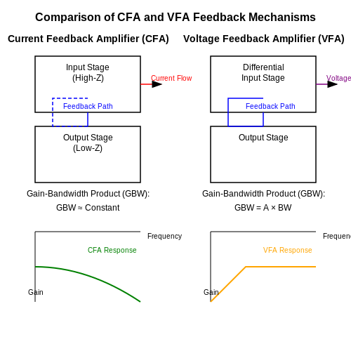
To lay the groundwork, it is crucial to recognize the foundational differences in how CFAs and VFAs leverage feedback in their operation. Voltage feedback amplifiers utilize the feedback loop to control the voltage at their inverting input. This approach allows for excellent linearity and a wide bandwidth, characteristics that have made VFAs prevalent in many applications.
On the other hand, current feedback amplifiers gather feedback from the output current instead of voltage. This method permits greater flexibility in bandwidth and enables CFAs to maintain consistent performance across varying loads, a significant advantage that will be explored later. The ability to react swiftly to the current change instead of relying on voltage feedback results in distinct operational characteristics that are particularly advantageous in high-frequency applications.
Gain Bandwidth Product and Slew Rate
One critical metric in amplifier performance is the gain-bandwidth product, which defines the frequency range over which an amplifier can maintain its gain. For VHAs, this product remains constant; as the amplifier's gain increases, the available bandwidth decreases, following the relationship:
where GBW is the gain-bandwidth product, Av is the amplifier gain, and f-3dB is the -3dB bandwidth. Conversely, CFAs exhibit a different behavior; the gain can be enhanced while still achieving a relatively consistent gain-bandwidth product due to their ability to adapt to the output current rather than being constrained by voltage feedback.
This distinction results in CFAs often outperforming VFAs in applications requiring rapid transient response and higher slew rates. The slew rate represents the maximum change in output voltage per unit time, and CFAs typically offer superior slew rates because they can draw from a larger current input, resulting in improved phase tracking across a wide frequency spectrum.
Application Relevance
In a practical context, the choice between CFAs and VFAs can significantly influence circuit design and its intended application. Current feedback amplifiers are particularly favored in applications like mixed-signal systems and RF analog designs, where their lower distortion at high frequencies and higher slew rate are beneficial. For example, in video signal amplification or fast signal processing tasks, the performance of CFAs becomes apparent when comparing noise figures and signal integrity margins against conventional VFAs.
Alternatively, voltage feedback amplifiers excel in low-frequency applications and situations where a high input impedance is paramount, such as in sensor signal conditioning or precision measurement circuits. The linearity and stability characteristics of VFAs make them ideal for systems requiring high fidelity and precision, such as audio amplifiers and instrumentation devices.
Conclusion
To summarize, while voltage feedback amplifiers have been a staple in diverse applications due to their linearity and ease-of-use, current feedback amplifiers provide valuable performance advantages in modern electronics that demand higher speed and bandwidth. Understanding the inherent properties of both amplifier types enables engineers and researchers to make informed decisions tailored to the specific requirements of their applications, thereby optimizing overall system performance.
2. Inverting Current Feedback Amplifier
2.1 Inverting Current Feedback Amplifier
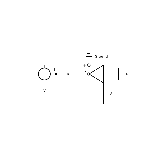
Current Feedback Amplifiers (CFAs) are increasingly popular due to their unique advantages over voltage feedback amplifiers, especially in applications where bandwidth and transient response are critical. In this subsection, we will delve into the inverting current feedback amplifier configuration, exploring its operational principles, mathematical foundation, and practical implications.
Understanding Current Feedback Amplifiers
To begin with, it is essential to understand the core difference between current feedback amplifiers and traditional voltage feedback amplifiers. In a CFA, the feedback network is designed in such a way that the output current is fed back to control the voltage at the inverting terminal. This architecture leads to a wider bandwidth and superior transient response, making CFAs suitable for high-speed applications, such as video processing and RF amplification.
The inverting configuration specifically provides a means to achieve negative feedback, which enhances stability and linearity in the amplifier's operation. In this setup, the input signal is applied to the inverting terminal while the non-inverting terminal is typically grounded. The feedback is primarily current-based, which differentiates it from voltage-based feedback in conventional operational amplifiers.
Mathematical Model of the Inverting Current Feedback Amplifier
Let’s derive the fundamental equations governing the behavior of the inverting current feedback amplifier. Assume the amplifier has a transconductance (gm) and a closed-loop gain (Acl) designated by the resistors in the feedback network.
In the inverting configuration, the input impedance can be expressed as:
Next, let’s consider the output voltage (Vout) in relation to the input current (Iin). The relationship can be given by:
Where the closed-loop gain (Acl) can be calculated as:
In this equation, Rf is the feedback resistor and Rg is the gain resistor connected across the inverting terminal. An important distinction here is that while conventional amplifiers focus on voltage gain, CFAs can handle higher frequencies thanks to their unique feedback mechanism.
Real-World Applications of Inverting Current Feedback Amplifiers
The advantages of inverting CFAs make them attractive for various applications:
- Video Signal Processing: The high bandwidth and fast transient response make CFAs ideal for amplifying video signals.
- High-Speed Data Communication: CFAs are used in applications such as clock recovery circuits, where speed is critical.
- Sensor Interfaces: CFAs can efficiently amplify signals from sensors in both industrial and consumer electronics.
In summary, the inverting current feedback amplifier provides distinct advantages in speed and bandwidth compared to traditional operational amplifiers. Understanding its operational principles and mathematical foundations equips engineers and researchers to apply them effectively in a range of modern electronic applications.
As we progress into more complex configurations of CFAs in subsequent sections, keep in mind the importance of component selection and circuit design in realizing the full potential of these versatile amplifiers.
2.2 Non-inverting Current Feedback Amplifier
The non-inverting current feedback amplifier (CFA) represents a unique topology in analog electronics, differentiating itself from the traditional voltage feedback amplifier (VFA) by exhibiting certain beneficial properties that enhance performance in various applications. To fully appreciate the nuances of this configuration, we will explore its operational principles, advantages, and corresponding mathematical foundations.
Operational Principles
At its core, the non-inverting CFA utilizes the current through an input configuration rather than the voltage difference. This design choice allows for greater stability and bandwidth, particularly in high-frequency applications. Unlike VFAs that establish their gain based on input voltage, CFAs set their gain by the feedback path, exploiting a current source configuration which provides lower output impedance.
Circuit Configuration
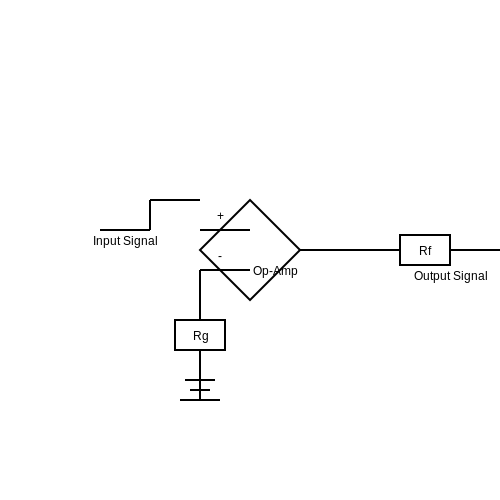
The classic non-inverting current feedback amplifier architecture comprises an operational amplifier (op-amp), along with two resistors that determine the gain. The configuration features the non-inverting input connected to the signal source while the inverting input receives feedback through a resistor network, typically designated as \( R_f \) and \( R_g \).
In this relationship, \( A \) denotes the voltage gain of the amplifier, while \( R_f \) and \( R_g \) signify the feedback and ground resistor values, respectively. It is crucial to note that the gain remains stable across different frequencies, making this configuration particularly advantageous in applications where bandwidth is critical.
Advantages of Non-inverting CFAs
Non-inverting current feedback amplifiers present several notable benefits over traditional designs:
- Higher Bandwidth: The design results in broader frequency performance, allowing them to handle faster signals.
- Improved Phase Margin: CFAs typically offer greater phase stability, lowering the risk of oscillation.
- Lower Distortion: Due to superior linearity in feedback paths, non-inverting CFAs may produce less distortion in output signals.
Real-World Applications
In real-world scenarios, non-inverting CFAs find their application in various domains. They are often implemented in:
- High-speed Signal Processing: Used in communications systems where signal integrity and bandwidth are paramount.
- Audio Equipment: Harnessed in amplifiers to maintain sound quality while managing high frequencies effectively.
- Sensors and Transducers: Vital in applications requiring accurate signal conditioning without load on the output stage.
Conclusion
In summary, the non-inverting current feedback amplifier offers significant advantages for rapid signal amplification and processing. By leveraging its unique feedback mechanism, this circuit design ensures stable gain and minimal distortion, providing an excellent choice for high-performance electronics. Understanding its operational characteristics and practical applications arms engineers with the tools to design versatile and effective analog systems.
2.3 Composite Current Feedback Amplifier
The Composite Current Feedback Amplifier (CCFA) is an advancement in the design of current feedback amplifiers that enables improved performance through the integration of multiple elements. This section explores the principles, advantages, and applications of CCFA, providing insight into why this configuration is increasingly relevant in modern electronic circuits.
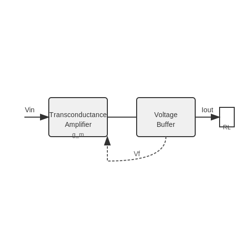
A CCFA is characterized by its dual feedback mechanisms, where both current and voltage feedback are utilized. This combination allows for enhanced linearity, a broader bandwidth, and reduced distortion compared to traditional amplifiers that rely solely on one feedback type. The basic architecture typically includes two stages: a transconductance amplifier stage followed by a voltage buffer. This design creates a compelling synergy between current-feedback and voltage-feedback approaches.
Design Principles
At the heart of the CCFA’s operation is the way it processes input signals. The input stage converts the voltage signal into a current, which is, in turn, fed back through additional components. This unique feedback mechanism helps stabilize gain and improve frequency response. To understand the dynamics of this amplifier, consider the following derivation of its transfer function.
Let us denote the transconductance of the amplifier as \(g_m\) and the load resistance as \(R_L\). The output current \(I_{out}\) can be expressed as:
This establishes the core relationship between the input voltage and output current. Next, when we consider the feedback effect, let \(V_f\) be the feedback voltage which is derived from the output current passing through the load resistor \(R_L\). Thus, the feedback voltage is represented as:
Substituting \(V_f\) back into the system, we can express a modified input voltage \(V_{in}'\) accounting for feedback:
Reinserting this modified input into the earlier expression for output current, we derive the new transfer function:
Simplifying this expression results in a comprehensive transfer function describing the composite feedback behavior of the amplifier, setting the foundation for rigorous analysis and application.
Advantages of Composite Design
The differentiated functionality of the CCFA brings with it several significant advantages:
- Higher Bandwidth: The combined effects of current and voltage feedback optimize the speed of the amplifier, effectively enlarging the operational bandwidth.
- Improved Linearity: By using a composite structure, harmonic distortion is minimized, enhancing overall signal fidelity.
- Flexibility in Applications: CCFAs can be employed in a variety of contexts, from audio signal processing to precision instrumentation and high-speed data transmission.
Real-World Applications
Due to its robust performance attributes, the Composite Current Feedback Amplifier has found its niche in various advanced applications:
- Signal Conditioning: CCFAs are prominently used in applications requiring high-speed signal amplification, such as telecommunications and audio systems.
- Medical Instrumentation: Their low distortion characteristics are vital in medical devices that demand high precision, such as electrocardiograms (ECGs).
- Video Processing: CCFA architecture is advantageous in video signal amplification, where wide bandwidth and low noise are critical.
In conclusion, the Composite Current Feedback Amplifier represents a sophisticated evolution in amplifier technology, offering enhanced performance through an innovative design that embraces both current and voltage feedback. As demand for high-speed and precise electronic systems continues to grow, understanding and implementing CCFAs will undoubtedly provide engineers and researchers with a competitive edge in developing next-generation applications.
3. Gain and Frequency Response
3.1 Gain and Frequency Response
Current feedback amplifiers (CFAs) offer unique advantages over traditional voltage feedback amplifiers, particularly in terms of gain and frequency response, critical parameters for high-performance applications such as audio amplification, signal processing, and instrumentation. This section delves into the interplay between gain, frequency response, and the operational mechanisms ingrained in CFAs.
Understanding Gain in Current Feedback Amplifiers
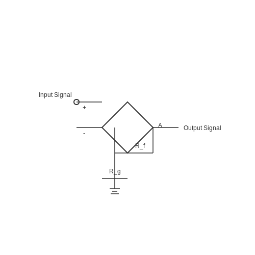
The gain of a CFA differs considerably from that of a conventional voltage feedback amplifier. In traditional voltage feedback configurations, the gain is primarily determined by external resistors, providing feedback to the inverting terminal with minimal impact on the non-inverting input. In contrast, CFAs utilize a current-based feedback mechanism, introducing a more dynamic flexibility in gain adjustments through the use of feedback resistors, specifically in the non-inverting configuration. The following general formula represents the relationship between the gain (A) and the feedback resistors:
Where:
- Rf is the feedback resistor connected from the output to the inverting input.
- Rg is the resistor connected from the inverting input to ground.
This equation underscores that the gain can be easily altered by adjusting the values of resistors, a clear advantage for designing variable gain applications.
Frequency Response Considerations
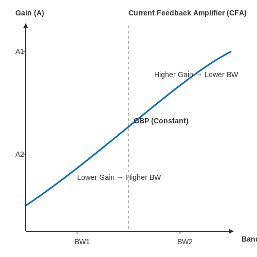
Frequency response in CFAs is characterized by a broader bandwidth compared to voltage feedback amplifiers. This capability stems from the fact that, in CFAs, the gain is not as dependent on the external capacitances that affect bandwidth in voltage feedback amplifiers. We can derive the bandwidth of a CFA by recognizing that its gain-bandwidth product remains constant:
For a CFA, as the gain increases, the bandwidth correspondingly decreases. This relationship exemplifies the trade-off crucial in amplifier design. One remarkable aspect worth noting is the concept of slight compression in gain with increasing frequency, an effect that can be minimized through optimal component selection and design techniques.
Practical Implications and Applications
In practical applications, the ability to maintain higher bandwidth while manipulating gain makes CFAs particularly useful in high-speed circuitry. They are often deployed in applications such as:
- High-frequency signal applications where rapid response times are essential.
- Audio equipment that demands high fidelity and minimal distortion, especially when varying levels of gain are needed.
- Instrumentation and measurement devices, where dynamic range management is paramount.
Moreover, as technology progresses toward higher frequencies at which electronic devices operate, CFAs represent an increasingly favorable choice in the design landscape.
In summary, the gain and frequency response in current feedback amplifiers exhibit a synergistic relationship that enables engineers and designers to optimize circuit performance for specific applications. By understanding these intrinsic characteristics, one can leverage CFAs to achieve superior results in a broad array of electronic systems.
Current Feedback Amplifiers
3.2 Input and Output Impedance
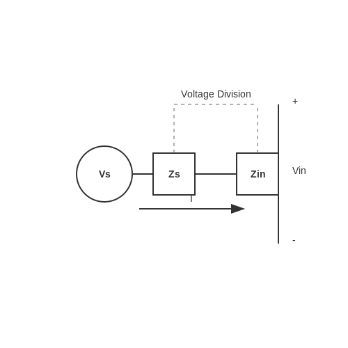
In the context of current feedback amplifiers (CFAs), the concepts of input and output impedance play crucial roles in determining the performance characteristics and application suitability of these devices. Understanding how impedance affects signal transmission and interaction with other circuit components can provide engineers with insights into the appropriate design decisions for specific applications. When studying input impedance, it is paramount to recognize that CFAs typically feature a high impedance at their inputs. This is beneficial as it minimizes the loading effect on previous stages in the signal chain, allowing for accurate signal transmission without significant attenuation. For a general CFA, the input impedance, \( Z_{in} \), is primarily determined by the resistance of the feedback network and the input characteristics of the amplifier’s transistors. To derive the input impedance, consider an ideal CFA where the feedback network consists of resistors \( R_f \) (feedback resistor) and \( R_g \) (ground resistor). The relationship can be expressed as: $$ Z_{in} \approx R_g + \beta R_f $$ where \( \beta \) is the current gain of the feedback network. By manipulating this expression, we can see how changes in the resistor values directly affect the input impedance, which is essential knowledge when selecting components for specific signal levels. On the other hand, the output impedance of CFAs is often notably low. This characteristic is advantageous for driving loads directly, ensuring that the output voltage remains stable across varying load conditions. A lower output impedance can prevent voltage drops when the amplifier drives heavy loads or operates in feedback configurations, facilitating greater fidelity in signal processing. The output impedance \( Z_{out} \) can be expressed approximately as: $$ Z_{out} \approx \frac{R_{out}}{1 + A_v \cdot \beta} $$ where \( R_{out} \) is the intrinsic output resistance of the amplifier, and \( A_v \) is the voltage gain. This relationship indicates that as the voltage gain increases, the effective output impedance decreases, enhancing the amplifier's ability to drive capacitive or inductive loads without significant feedback interaction. Through careful design consideration of both the input and output impedance, engineers can maximize the performance of CFAs in a variety of applications, including high-speed data communication systems, instrumentation, and audio amplification. In practical applications, measuring the impedance can be accomplished through methods such as small-signal analysis or using dedicated impedance analyzers. Ensuring accurate impedance matching between different stages of amplification can significantly improve overall system performance, granting optimal function across the entire operation spectrum. Ultimately, a comprehensive understanding of impedance characteristics is vital for harnessing the full potential of current feedback amplifiers, revealing pathways for enhanced signal integrity and performance in advanced electronic designs.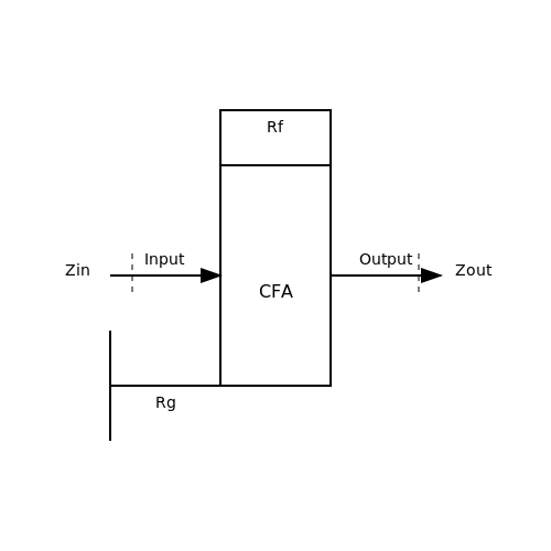
3.3 Stability and Feedback Factors
Current Feedback Amplifiers (CFAs) stand out in their ability to manage signal amplification while retaining remarkable stability. Understanding the stability and feedback factors in CFAs is crucial for engineers and researchers, as these parameters dictate the performance, bandwidth, and overall operational integrity of the amplifier. By delving into the mathematical underpinnings of CFAs, we can ascertain how feedback influences stability and performance.
Understanding Feedback in CFAs
Feedback in the context of CFAs refers to the method by which a portion of the output signal is fed back into the input. This can either be positive or negative feedback, with negative feedback being generally preferred in amplification applications for improving stability and bandwidth. In CFAs, the feedback mechanisms can determine system behavior, affecting parameters such as gain, bandwidth, and phase margin.
The feedback factor, β, represents the portion of the output voltage that is fed back to the input. It is defined mathematically as:
In this equation, Vout is the output voltage of the amplifier and Vin is the input voltage. An effective control of the feedback factor is essential for ensuring desired performance characteristics.
Stability Considerations
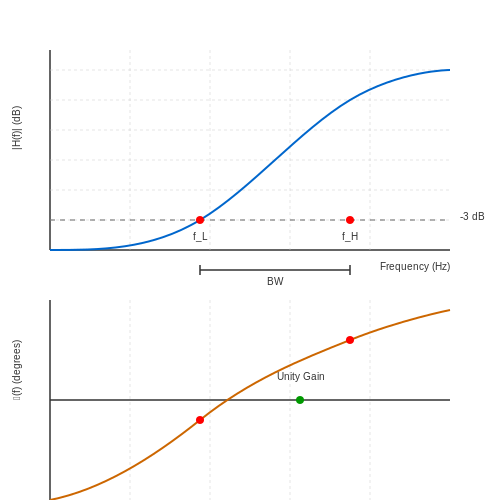
Stability in CFAs is often quantified through the phase margin and the gain margin. The phase margin is particularly crucial as it indicates how far the system is from oscillation. Phase margin (PM) can be defined as:
where φcross is the phase at the gain crossover frequency (the frequency at which the gain is unity). A greater phase margin implies better stability, equating to a lower likelihood of unwanted oscillation. Conversely, a phase margin that approaches zero signifies marginal stability, which can lead to oscillations in a feedback loop.
Moreover, the gain margin provides another dimension of stability assessment, indicating how much gain can be increased before instability occurs. Both margins need to be optimized to ensure robust operation of the CFA across its specified range.
Practical Relevance of Stability
A practical example of stability considerations in CFAs occurs in audio processing applications. In these systems, it is imperative to maintain clarity and fidelity in sound reproduction without introducing distortion or undesired oscillations. A well-designed CFA with adeptly controlled feedback factors ensures that the audio signal remains free of artifacts while achieving the required power output.
Determining Stability in Design
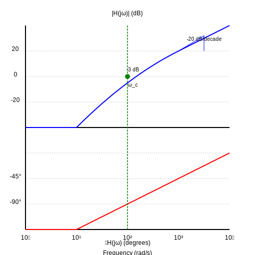
When designing CFAs, engineers typically employ simulation tools to assess stability. These tools can analyze the transient response and frequency response of the amplifier, thus allowing the designer to manipulate feedback factors appropriately to achieve desired performance metrics. The application of Bode plots in these analyses offers a visual interpretation of both gain and phase margins, making stability discussions more tangible.
Moreover, stability can be enhanced through additional design strategies such as compensation techniques, which may involve adding lead or lag compensation that alters the phase response to provide adequate margins.
In conclusion, a thorough understanding of stability and feedback factors is critical when working with Current Feedback Amplifiers. Engineers must balance the benefits of feedback with the potential risks of instability. This knowledge not only aids in optimizing amplifier performance but also ensures reliability across applications—from audio systems to precision instrumentation.
4. Audio Amplification
4.1 Audio Amplification
Current Feedback Amplifiers (CFAs) are pivotal in audio amplification due to their distinctive characteristics, which contribute to high performance and versatility. A CFA operates on the principle of providing feedback based on the current rather than the voltage, giving it unique advantages when dealing with audio signals. This section delves into the operational nuances of CFAs in audio applications, examining their benefits, practical implementations, and theoretical foundations.
Principles of Operation
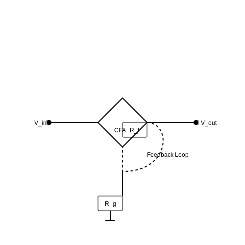
At the heart of a CFA is its feedback mechanism, which allows for an accurate and efficient amplification of audio signals. Traditional voltage feedback amplifiers (VFAs) function by comparing the output voltage against a reference voltage. In contrast, a CFA utilizes the current flowing through the feedback resistor, enabling it to achieve lower distortion, wider bandwidth, and improved transient response.
The essential operational dynamics of a CFA can be summarized with the following key advantages:
- High Slew Rate: CFAs are capable of rapid changes in output voltage, making them ideal for amplifying dynamic audio signals.
- Low Output Impedance: This feature allows CFAs to drive large capacitive loads without sacrificing stability or performance.
- Reduced Distortion: Since CFAs respond to current instead of voltage, they exhibit lower levels of harmonic distortion, making them suitable for high-fidelity audio applications.
Theoretical Background
To mathematically express the performance of CFAs in audio applications, we begin with the basic feedback equation:
In this equation:
- Vout: Output voltage
- A0: Open-loop gain of the amplifier
- Vin: Input voltage
- Rf: Feedback resistor
- Rg: Ground resistor
The gain formula illustrates how CFAs can be finely tuned for specific audio applications through careful selection of feedback components. The ratio of Rf to Rg defines the overall gain, making it relatively straightforward to achieve desired amplification levels.
Practical Applications in Audio Engineering
The advantages presented by CFAs make them particularly appealing in various audio amplification contexts, including:
- High-Fidelity Audio Systems: CFAs enhance the sound quality in home theater setups, delivering clear and precise audio.
- Professional Audio Equipment: In studios, CFAs are used to amplify signals without compromising the integrity of the sound, an essential aspect for recording and mixing.
- Portable Audio Devices: Their compact size and efficiency make CFAs suitable for battery-operated devices, enabling high-quality audio amplification without significant power draw.
In summary, the integration of CFAs in audio applications is driven by their operational efficiencies, low distortion characteristics, and adaptability to various equipment configurations. As demand for high-quality sound continues to grow, the relevance of CFAs in audio systems will likely expand, compelling audio engineers and designers to leverage their unique advantages.
Through understanding the theoretical foundations and practical applications of Current Feedback Amplifiers in audio amplification, it's clear that these devices not only enhance performance but also redefine the standards of audio quality.
Current Feedback Amplifiers
4.2 RF and Microwave Applications
Current feedback amplifiers (CFAs) have garnered significant attention in the realms of RF (Radio Frequency) and microwave applications due to their unique operational characteristics and adaptability to high-frequency environments. Unlike traditional voltage feedback amplifiers, CFAs provide enhanced bandwidth and flexibility, making them particularly suitable for tasks that involve high-speed signal processing.
At the core of RF and microwave systems lies the requirement for low noise, high linearity, and high gain. CFAs inherently possess the ability to achieve these parameters. Their wide bandwidth is attributed to the reduced feedback capacitance, facilitating improved transient response. This trait is fundamental in applications such as radar systems, communication transmitters, and cable TV signal amplification.
Consider a practical realization: in radar applications, signal integrity and processing speed are paramount. The agility of CFAs allows them to process incoming signals with minimal distortion, thereby ensuring accurate target detection. This operational advantage is especially critical in modern phased array radars, where rapid signal switching capabilities are essential. Additionally, the frequency response of CFAs allows for effective amplification in the GHz range, crucial for microwave systems.
Performance Characteristics
Understanding the performance characteristics of CFAs in RF and microwave applications involves analyzing gain, bandwidth, and noise figure. The gain-bandwidth product (GBP) of a CFA remains nearly constant across a wide range of frequencies, making it a versatile choice for designers aiming for high performance without being confined to narrow frequency ranges.
Moreover, the noise performance of a CFA can be optimized using appropriate biasing techniques and careful selection of components. A CFA configured for optimal noise figure will outperform traditional amplifiers in terms of signal-to-noise ratio (SNR), which is a critical consideration in RF applications like low-noise amplifiers (LNAs) for receivers.
Mathematical Analysis
To quantify the gain-bandwidth product of a CFA, the relationship can be derived from the general feedback amplifier configuration. The gain \( A \) in a current feedback configuration is defined as:
Here, \( G \) is the transconductance gain, \( R_f \) is the feedback resistor, and \( R_{in} \) is the input impedance.
The bandwidth \( BW \) can be expressed as:
This demonstrates how the bandwidth of a CFA is inversely proportional to its voltage gain, underscoring the importance of careful design in maximizing bandwidth without sacrificing gain efficiency.
Real-World Implementations
Numerous implementations showcase the utility of CFAs in RF and microwave systems. For example, voltage-controlled oscillators (VCOs) often leverage the high-performance qualities of CFAs to maintain frequency stability while avoiding phase noise. This multifaceted utilization demonstrates the versatility of CFAs across various applications, including but not limited to:
- Signal amplification in cellular communication systems, where signal clarity is crucial for maintaining connectivity and data integrity.
- Application in optical communications, where high frequency and low distortion requirements necessitate advanced amplification solutions.
- Utilization in satellite communication systems for signal conditioning and processing to combat the challenges posed by extensive signal journey distances.
In conclusion, current feedback amplifiers represent a compelling choice for RF and microwave applications due to their superior performance characteristics, adaptability, and mathematical rigor. Their ability to deliver low noise, high gain, and broad bandwidth is essential in meeting the demanding requirements of contemporary communication systems and beyond.
4.3 Signal Conditioning and Filtering
Current feedback amplifiers (CFAs) have gained considerable attention in modern electronic circuits due to their remarkable bandwidth and transient response characteristics. A crucial aspect of utilizing CFAs in various applications is the process of signal conditioning and filtering, which ensures the amplification process aligns with desired specifications, particularly in precision applications where signal integrity is paramount.
Signal conditioning involves manipulating an input signal to meet the requirements of the subsequent stage in a system. This may encompass amplification, attenuation, filtering, and level shifting. In conjunction with CFAs, effective signal conditioning leads to reduced noise, enhanced signal quality, and improved overall performance.
Understanding Filtering in Current Feedback Amplifiers
Filtering is an integral component of signal conditioning, as it serves to remove unwanted frequency components from a signal while allowing the desired frequencies to pass. In applications such as audio processing, instrumentation, and communications, filtering ensures that only the necessary information is retained, which is especially critical when utilizing CFAs, known for their high-speed capabilities.
The design of filters can take many forms, including low-pass, high-pass, band-pass, and band-stop filters, each playing a unique role in signal processing. Performing filtering with CFAs can often provide advantages due to their expanded frequency bandwidth and no phase reversal characteristics, which are particularly beneficial in maintaining stability in feedback systems.
Implementing a Simple Low-Pass Filter
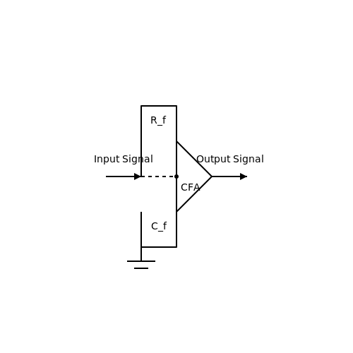
A practical example of filtering with CFAs is the design of a simple low-pass filter (LPF) configuration. In this circuit, the CFA serves as an amplifier with a feedback resistor and capacitor creating a frequency-dependent response. The transfer function is critical for understanding the circuit's performance, specifically the cutoff frequency at which the signal begins to attenuate.
The cutoff frequency, denoted as \( f_c \), is derived from the feedback components. In a first-order low-pass filter configuration, the cutoff frequency can be calculated using:
Here, \( R_f \) is the feedback resistor, and \( C_f \) is the feedback capacitor. When designing the filter, proper selection of these components will establish the desired cutoff frequency, enabling you to filter out noise while preserving the integrity of the primary signal.
Moreover, higher-order filters can be achieved by cascading multiple first-order filters, leading to sharper roll-off characteristics and more precise filtering. However, it is essential to consider stability and phase margin in such designs, as cascading filters increases the complexity of the feedback loop, potentially leading to oscillations.
Practical Applications of CFAs with Filtering
The implementation of signal conditioning and filtering using current feedback amplifiers finds applications in various domains:
- Audio Processing: Many combinations of CFAs are utilized in equalizers and tone control circuits, enhancing sound quality by removing unwanted frequency content.
- Instrumentation: CFAs equipped with filtering capabilities improve the accuracy of measurements taken from sensors by eliminating noise and amplifying signals of interest.
- Communication Systems: Filters integrated with CFAs help in ensuring signal fidelity by filtering out interference in sensitive communication links.
In conclusion, the synergistic use of current feedback amplifiers combined with effective signal conditioning and filtering becomes a crucial methodology in modern electronics, enhancing performance and reliability across various applications. Understanding the fundamentals of filter design and their interaction with CFAs empowers engineers and researchers to optimize their systems and achieve desired outcomes.
5. Selecting Components
5.1 Selecting Components
When designing a current feedback amplifier (CFA), selecting the right components is crucial to optimize performance and meet specific application requirements. The core functionality of a CFA heavily relies on the characteristics of the operational amplifiers (op-amps), feedback components, and load elements utilized in the design. In this section, we will explore the key factors that should be taken into account when selecting each component, providing a structured approach to ensure robust and high-performance designs.Op-Amps for Current Feedback Amplifiers
The selection of op-amps is fundamental to the performance of any CFA. Unlike voltage feedback amplifiers, CFAs utilize a unique feedback mechanism that allows for wide bandwidth and low distortion. Most importantly, the op-amps used must support high slew rates, as the current feedback mechanism can produce rapid changes in output voltage. Here are several considerations and specifications to evaluate:- Slew Rate: Look for op-amps with a minimum slew rate higher than 3 V/µs to ensure accurate reproduction of high-frequency signals.
- Gain-Bandwidth Product (GBW): Choose an op-amp with a GBW that exceeds the required bandwidth of your signal. A ratio of 10:1 is often recommended.
- Input Impedance: A high input impedance minimizes the loading effect on the previous stage, maintaining signal integrity.
Feedback Resistors
In CFA designs, the feedback network plays a crucial role in determining the amplifier's stability and gain settings. The values chosen for feedback resistors will dominate the overall gain, which in turn affects bandwidth and phase margin. The connection of feedback components around the op-amp requires meticulous attention: 1. Resistor Values: Use precision resistors with a tolerance of 1% or better to maintain gain accuracy. 2. Temperature Coefficients: Select resistors with low temperature coefficients to improve thermal stability. 3. Feedback Configuration: The selection between voltage feedback and current feedback configurations may alter the effective gain. Current feedback often yields higher bandwidth at lower gain settings, making it adaptable for various applications.Capacitors in Feedback Networks
Capacitors are often placed in the feedback path or at the output to control frequency response and stability: - Output Bypass Capacitors: These capacitors help filter high-frequency noise and increase stability. A value in the range of 10nF to 100nF is commonly used. - Compensation Capacitors: Placing a capacitor in parallel with the feedback resistor can stabilize the feedback loop, creating a dominant pole that mitigates high-frequency gain.Real-World Applications and Design Considerations
Understanding and selecting the right components has substantial implications across various applications, such as high-speed video amplifiers, RF applications, and sensor interfaces. For instance, in high-speed communication systems, where bandwidth and signal integrity are paramount, the correct selection leads not only to adherence to design specifications but also impacts the reliability and overall performance of the system. When approaching component selection, it is often helpful to prototype with different configurations to empirically determine optimal settings before committing to a specific design. Advanced simulation tools can also provide insights into signal behavior under varied conditions, allowing for fine-tuning of component values based on performance outcomes prior to physical implementation. In summary, the careful selection of each component in a CFA design must reflect both theoretical principles and practical outcomes. By prioritizing specifications such as slew rate, feedback configuration, and temperature stability, one can design amplifiers that achieve desired performance targets reliably.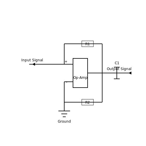
5.2 Common Design Pitfalls
Current Feedback Amplifiers (CFAs) are sophisticated electronic components used in numerous applications, ranging from audio amplification to signal processing. While they offer several advantages, including wide bandwidth and high slew rates, several design pitfalls can significantly impact their performance. This section will address these common mistakes, emphasizing their implications and how to avoid them.
Instability and Poor Phase Margin
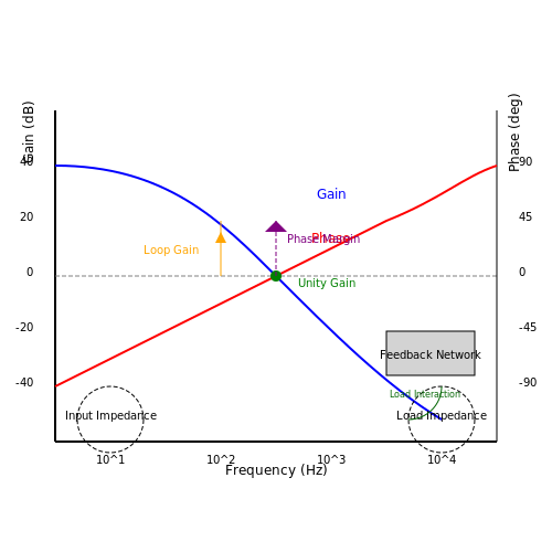
One of the most recurrent issues in CFA design is instability, often indicated by poor phase margin in frequency domain analyses. Phase margin is a measure of how close the amplifier is to oscillation; a phase margin of less than 45 degrees typically indicates instability. In CFAs, this can arise due to inadequate feedback or improper compensation. When designing a CFA, careful consideration must be given to:
- The loop gain: High loop gain can cause severe phase shifts, leading to instability.
- The frequency response: Non-idealities such as parasitic capacitances can adversely affect phase margins.
- Temperature variations that can lead to changes in transconductance.
To enhance phase margins, employing frequency compensation techniques, such as dominant pole compensation, can be crucial. This involves introducing a dominant pole that ensures stable operation across the desired frequency range.
Inadequate Power Supply Decoupling
Power supply decoupling is essential for maintaining stable amplifier performance. Insufficient decoupling can lead to fluctuations in power supply voltage caused by load transients or external noise sources. These fluctuations can severely degrade performance by inducing distortion or unwanted oscillations. It is essential to:
- Utilize low equivalent series resistance (ESR) capacitors close to the amplifier's power pins.
- Ensure a good ground connection to minimize noise pickup.
For high-frequency applications, the decoupling strategy should also consider the self-resonant frequency of capacitors to prevent resonance effects that could lead to instability.
Overlooking Input Impedance Matching
Another frequent oversight is failing to consider the input impedance of the CFA. Mismatched impedances can lead to signal reflections, signal loss, and degradation of frequency response. Depending on the application, it may be necessary to employ matching networks or input buffers to achieve optimal performance. Understanding the source impedance and adapting the CFA's input stage can mitigate these issues.
Ignoring Non-linear Effects
Many designers assume linear behavior in CFAs, which can lead to suboptimal performance, especially at higher signal levels. Non-linearities can manifest as distortion in output signals. To address this, designers should:
- Characterize the amplifier through comprehensive simulations that include non-linear models and transient analyses.
- Assess the impact of device parameters such as biasing and feedback resistors on non-linear performance.
By incorporating comprehensive non-linear modeling techniques, engineers can predict the operating limits of the CFA and improve the circuit's linearity.
Understanding Load Interaction
Load interaction is another critical consideration that can impact performance when designing CFAs. The output of a CFA is affected not only by the feedback network but also by the load it drives. A load with low resistance can draw substantial current, changing the behavior of the amplifier. To counteract load interaction, the following strategies can be employed:
- Designing the output stage with appropriate current-driving capabilities to handle varying loads without significant performance loss.
- Using series or parallel output resistors to stabilize the output under load changes.
As such, careful load analysis is necessary during the design phase to ensure that the amplifier performs uniformly across its intended operational range.
Final Words on Best Practices
In summary, navigating the complexities of CFA design requires both theoretical understanding and practical experience. By being mindful of these common pitfalls — instability due to poor phase margin, inadequate power supply decoupling, input impedance mismatches, non-linear effects, and load interactions — engineers and designers can greatly improve their design outcomes. Taking a proactive approach and employing best practices throughout the design process will yield CFAs that perform reliably in real-world applications.
5.3 Troubleshooting Performance Issues
Understanding the Importance of Troubleshooting
Troubleshooting performance issues in current feedback amplifiers (CFAs) is critical for ensuring optimal functionality in various electronic applications. CFAs, known for their unique feedback mechanism, offer advantages such as wide bandwidth and high slew rates. However, when they encounter performance issues, their effectiveness can diminish, leading to significant impacts on overall circuit behavior. Recognizing the symptoms of these issues is the first step towards effective resolution.Common Symptoms of Performance Issues
Before diving into troubleshooting methods, it's essential to understand the common symptoms one may encounter with CFAs:- Distortion: Unexpected harmonic distortion can result from nonlinearities in the amplifier or feedback path.
- Noise: Increased noise levels can indicate grounding issues or unwanted feedback.
- Gain variations: Inconsistent gain may point to component tolerance issues or variations in power supply voltages.
- Phase shift: Unexpected phase shifts can lead to instability in closed-loop configurations.
Step-by-Step Troubleshooting Approach
1. Verifying Component Values Begin by examining the values of resistors, capacitors, and other components in your circuit. Mismatched or faulty components can cause substantial shifts in performance. Use a multimeter to measure component values directly, ensuring they align with the design specifications. 2. Checking Power Supply Integrity Fluctuations in power supply voltage can have significant repercussions on amplifier performance. Utilize an oscilloscope to observe supply voltage stability under different load conditions. A stable, clean power supply is crucial for optimal amplifier operation. 3. Feedback Loop Inspection Next, inspect the feedback network. Ensure all connections are solid, with no open or shorted paths. Tools like network analyzers can help analyze the feedback loop for unexpected frequency response or feedback gain issues. 4. Thermal Management Excessive heating can lead to performance degradation. Assess the thermal environment of your CFA by measuring component temperatures after prolonged operation. If overheating is detected, consider improving heat dissipation through better PCB layout or heat sinking. 5. Load and Stability Analysis Analyze the load connected to the amplifier. Excessive loading or reactive components can destabilize the amplifier. Use simulation tools such as SPICE to model your amplifier under various loading conditions, helping to identify potential stability issues. 6. Simulation and Modelling Utilize advanced simulation software to replicate and analyze the CFA's behavior under ideal and non-ideal conditions. This allows for a better understanding of potential performance issues that might not be evident in a physical prototype.Practical Example: Identifying Gain Variations
Consider a specific case where the gain of a CFA is significantly lower than expected. Begin by verifying component values and checking the power supply. Upon investigation, you might discover that a feedback resistor has drifted from its nominal value due to thermal stresses. To address this, replace the resistor with a higher tolerance component and recalibrate the gain. Following these steps, re-evaluate the overall circuit performance. This methodical approach not only resolves the immediate issue but also arms you with better knowledge for future projects.Conclusion
Troubleshooting current feedback amplifiers requires a systematic and delicate approach. By understanding the nuances of potential performance issues and employing a structured troubleshooting methodology, one can effectively restore an amplifier's functionality. Mastering this skill is vital for engineers and researchers, ensuring high-performance operations in diverse electronic circuits.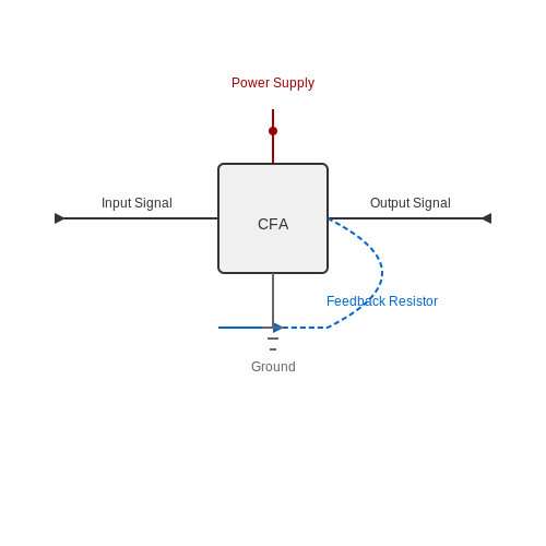
6. Key Textbooks and Journals
6.1 Key Textbooks and Journals
- Analog Integrated Circuit Design by Tony Chan Carusone, David Johns, Kenneth Martin — This comprehensive textbook covers advanced topics on analog circuit design, including feedback amplifiers, with illustrative examples and problem sets for deeper understanding.
- IEEE Journal of Solid-State Circuits — This leading journal features research papers on solid-state circuits, including current feedback amplifiers, offering simulation results and experimental data for engineers and researchers.
- Feedback Networks: Theory and Circuit Applications by Thomas H. Lee — Focuses on the theory behind feedback networks in circuits with practical design applications to gain a solid foundation in current feedback amplifiers and other feedback systems.
- Analog Integrated Circuits and Signal Processing Journal — A hybrid journal showcasing articles on state-of-the-art analog integrated circuit designs, frequently featuring cutting-edge work on current feedback amplifiers.
- Design with Operational Amplifiers and Analog Integrated Circuits by Sergio Franco — A deep dive into the design of analog circuits, with a dedicated section on current feedback amplifiers and practical circuit design techniques.
- IEEE Transactions on Circuits and Systems I: Regular Papers — This publication provides significant insights into circuit systems focusing on innovative research in the realm of current feedback amplifiers through detailed theoretical and experimental analysis.
- International Journal of Electronics — Publishes articles on advanced electronics research, with occasional features on current feedback amplifiers, offering industrial applications and theoretical developments.
6.2 Online Resources and Tutorials
For advanced readers looking to deepen their understanding of current feedback amplifiers (CFAs), a variety of online resources and tutorials are available that cover both theoretical aspects and practical applications. The following curated list provides links to detailed and high-quality content, ensuring a comprehensive learning experience.- Analog Devices Education Library — This resource offers a comprehensive range of tutorials and lectures on amplifiers, including current feedback designs. It provides practical examples and application notes helpful in mastering amplifier concepts.
- Texas Instruments CFA Design Guide — A detailed application note from Texas Instruments focusing on the design techniques specific to current feedback amplifiers with accompanying illustrations and examples.
- Electronics Tutorials: Amplifier Basics — While primarily about general amplifier principles, this site includes discussions on different amplifier types, including CFAs, offering both theoretical explanations and practical insights.
- EDN Network: Phase Reversal in Op-Amps — Offers insights into phase reversal issues commonly encountered in amplifiers, touching upon advanced operational techniques relevant to current feedback models.
- Digi-Key Current Feedback Amplifiers Article — An article discussing the advantages of CFAs along with their application in real-world designs, highlighting both theoretical aspects and industry applications.
- ScienceDirect: Advances in CFA Technology — A peer-reviewed article available through ScienceDirect, exploring recent advancements in the technology and applications of current feedback amplifiers.
- YouTube: EE Knowledge's CFA Tutorials — A series of video tutorials on YouTube focusing on current feedback amplifiers, showcasing practical design exercises and hands-on projects.
6.3 Standards and Specifications
The accurate and effective design of current feedback amplifiers (CFAs) relies heavily on adherence to specific standards and specifications. These parameters ensure not only optimal functionality but also compatibility with broader systems in professional applications. Understanding these standards is crucial for advanced practitioners aiming to leverage CFAs in practical and research environments.
Global and Industry Standards
Adhering to global standards is paramount for engineers and researchers who want to ensure their designs are robust, interoperable, and satisfy pervasive industry requirements. Over time, several organizations have established guidelines for evaluating the performance and safety of current feedback amplifiers.
- IEEE Standards: The Institute of Electrical and Electronics Engineers (IEEE) is a pivotal body in establishing standards across electronic and electrical domains. Standards for CFAs focus on defining parameters such as bandwidth, slew rate, and harmonic distortion.
- IEC Standards: The International Electrotechnical Commission (IEC) provides guidelines that emphasize the environmental compatibility and energy efficiency of electronic components, including CFAs.
- JEDEC Standards: This standardization body focuses more on the semiconductor aspects of amplifiers, providing crucial specifications for fabrication processes.
Key Specifications
To successfully implement CFAs, one must comprehend and apply key specifications that govern their performance. This subsection will discuss a few fundamental specifications pivotal to CFA operation:
Bandwidth and Slew Rate
The bandwidth of a CFA often exceeds that of traditional op-amps due to its intrinsic design characteristics. The fast response time is largely attributed to the high slew rate, which represents the maximum rate of change of the output voltage per unit of time. These specifications make CFAs suitable for applications requiring rapid signal processing.
Let's delve into the math behind calculating slew rate:
Where SR is the slew rate, ΔV is the change in voltage, and Δt is the time duration during which this change occurs. By optimizing these parameters, CFAs can efficiently handle signals with high-frequency components.
Input Impedance
The input impedance of a CFA is unique due to its accurate current feedback loop. While voltage feedback amplifiers typically possess high input impedance to minimize loading effects, CFAs maintain a lower input impedance, enhancing their bandwidth and speed characteristics. The optimized impedance allows CFAs to interface effectively with various signal sources.
Output Impedance
High output drive capability is a crucial feature of CFAs, facilitated by their relatively low output impedance. This quality enables CFAs to drive heavy loads without significant voltage drops, a necessity in applications such as video and RF transmissions where signal integrity is paramount.
Practical Applications and Case Studies
Understanding the standards and specifications allows CFAs to be implemented in a variety of advanced applications. Here are some real-world instances where CFAs have been effectively employed:
- Video Amplification: CFAs' high slew rate and wide bandwidth are leveraged in video amplifiers to process fast video signals with minimal distortion.
- RF Communication: Their ability to handle high-frequency signals makes them an excellent choice for RF transmitters and receivers where signal clarity is crucial.
- Medical Imaging: The precision and speed of CFAs are harnessed in devices such as ultrasound equipment, where accurate signal amplification is vital.
In conclusion, the understanding and application of standards and specifications are fundamental in harnessing the full potential of current feedback amplifiers. By considering these parameters, engineers and researchers can effectively design systems that are not only efficient but also reliable and compliant with industry standards.