


40w no tune amp
#FM broadcast
#RF amplifier
#40W amplifier
#low power exciter
#RF interference
#broadcast band
#RF radiation
#commercial kits
#community radio
#power boost

Description: To enhance the output power of low-power FM broadcast band exciters, various options are available commercially, including both kits and pre-assembled units. Resources such as "How to be a Community Radio Station" provide links to reviews of some popular exciters. However, unwanted spurious RF radiation can cause interference to other electromagnetic spectrum users, leading to potential visits from regulatory authorities, along with risks of equipment confiscation, fines, and possibly imprisonment. The quality of many schematics and designs for FM broadcast equipment found online is often inadequate. The information available on VHF RF power amplifiers is particularly lacking, with some designs utilizing outdated components like the TP9380. This design is based on a newer MOSFET device, which offers several advantages. Given that most designs available online are over a decade old, using a recently introduced device can extend the design's useful life. This design serves as an example to illustrate the amount of information necessary for someone without advanced skills to successfully build this amplifier. A skilled individual can build from minimal design information, while those lacking experience will require detailed instructions. The amplifier design utilizes the Motorola MRF171A MOSFET, introduced in 1998. It is important not to confuse this with the older, discontinued MRF171 device. Motorola frequently updates its RF power device product portfolio. Initial feasibility assessments were conducted using a linear RF and microwave simulation package, specifically Supercompact, although the version used is not recommended. Motorola provides S-parameters and large-signal single-ended impedances for the device. These S-parameters are measured at a quiescent drain current of 0.5 A, representing an improvement in device characterization, as traditional measurements were often taken at lower drain currents. While S-parameter data at 0.5 A could serve as a useful starting point, the design is primarily based on large-signal impedances. These impedances are determined by tuning the device for optimal performance at each test frequency in a generic test fixture, followed by using a vector network analyzer to measure the complex impedance looking back into the matching network, terminated with 50 ohms. This process is executed for both the input and output matching networks. The benefit of large-signal impedance data is that it can be measured at the actual output power the device is designed to generate, making it more relevant for power amplifier applications. However, it should be noted that large-signal impedances only facilitate the synthesis of input and output matching networks and do not provide information regarding gain, efficiency, noise performance, or stability of the resulting amplifier.
C1: 1pF, 30.2596pF, 120pF
C2: 1pF, 21.8507pF, 120pF
L1: 1nH, 72.7228nH, 80nH
C3: 1pF, 179.765pF, 180pF
L2: 1nH, 30.4466nH, 80nH
Circuit netlist:
cap 1 2 c=c1
cap 2 0 c=c2
ind 2 3 l=l1
cap 3 0 c=c3
ind 3 9 l=l2
res 9 0 r=33
;gate bias feed resistor one 9 mrf171ip
;reference to 1 por
The circuit design employs a combination of capacitors and inductors to create a matching network that optimizes the performance of the MRF171A MOSFET. The capacitors (C1, C2, C3) and inductors (L1, L2) are carefully selected to ensure the correct impedance matching at the desired operating frequency. The resistor connected to the gate bias serves to stabilize the operating point of the MOSFET, ensuring reliable performance. The netlist provides a clear representation of the connections and components used in the circuit, facilitating the construction of the amplifier by those with appropriate expertise.To boost the output power of low power FM broadcast band exciters, a number of these are available commercially, both as kits and ready made. See How to be a Community Radio Station for links to reviews of some of the more popular exciters. Unwanted spurious RF radiation, resulting in interference to other users of the electromagnetic spectrum, th
us risking a visit from the state, and consequent risk of equipment confiscation, fines, and possibly imprisonment. I believe the quality of the vast majority of schematics and designs for FM broadcast equipment available on the internet to be far from satisfactorily.
See my advice on building from plans on the web. In particular the information available on VHF RF power amplifiers is even more desperate, for example designs using dinosaurs of devices such as the TP9380. This design is based on a new MOSFET device, with the attendant advantages of Seeing as most of the designs on the web are over 10 years old, using a recently introduced device should maximise the useful life of the design.
I also use this design as a vehicle to demonstrate the amount of information required for a third party not equipped with mind-reading skills to successfully build this amplifier. The point is this: if a person is sufficiently skilled and experienced to build something from scanty design information, for instance just a schematic, they are just as able to build it from no information at all.
Conversely, a person not at that skill and experience level will require detailed instructions to succeed. The amplifier design is based on the recently introduced (1998) Motorola MRF171A MOSFET ( MRF171A data sheet in PDF format).
Do not confuse this with the older, now discontinued, MRF171 device. January 2002 - Motorola changes their RF power device product portfolio more often than some people change their underparts. It looks like Motorola have unloaded this device on to M/A-Com. The initial feasibility was performed using a linear RF and microwave simulation package, specifically Supercompact.
The version used was 6. 0, which quite frankly I consider a piss-poor piece of software and don`t recommend at all. For this device, Motorola provide S parameters and large signal single ended impedances. The S parameters are measured at 0. 5 A quiescent drain current, which represents a step forward in device characterisation, as traditionally S parameters tended to be measured at quite low drain currents. Whilst this is satisfactory for small-signal devices, the use of S parameters measured at small drain currents is limited for power amplifier design.
While the S parameter information measured at 0. 5 A could have provided a useful design starting point, I choose to base the design on the single ended large-signal impedances. These are measured by the device manufacturer by tuning the device up for best performance at each test frequency in a generic test fixture.
The test device is then removed, and a vector network analyser is used to measure the complex impedance looking back into the matching network, whilst these are terminated with 50 R. This procedure is carried out for the input and output matching networks. The advantage of large signal impedance data is that it can be measured at the actual output power that the device is designed to generate, and as such are more representative in a power amplifier scenario.
Note the large-single impedances only provide information to enable an input and output matching network to be synthesised, they provide no information about the likely gain, efficiency, noise performance (if relevant) or stability of the resulting amplifier. C1: 1PF 30. 2596PF 120PF C2: 1PF 21. 8507PF 120PF L1: 1NH 72. 7228NH 80NH C3: 1PF 179. 765PF 180PF L2: 1NH 30. 4466NH 80NH BLK ;Circuit netlist cap 1 2 c=c1 cap 2 0 c=c2 ind 2 3 l=l1 cap 3 0 c=c3 ind 3 9 l=l2 res 9 0 r=33 ;gate bias feed resistor one 9 mrf171ip ;reference to 1 por
C1: 1pF, 30.2596pF, 120pF
C2: 1pF, 21.8507pF, 120pF
L1: 1nH, 72.7228nH, 80nH
C3: 1pF, 179.765pF, 180pF
L2: 1nH, 30.4466nH, 80nH
Circuit netlist:
cap 1 2 c=c1
cap 2 0 c=c2
ind 2 3 l=l1
cap 3 0 c=c3
ind 3 9 l=l2
res 9 0 r=33
;gate bias feed resistor one 9 mrf171ip
;reference to 1 por
The circuit design employs a combination of capacitors and inductors to create a matching network that optimizes the performance of the MRF171A MOSFET. The capacitors (C1, C2, C3) and inductors (L1, L2) are carefully selected to ensure the correct impedance matching at the desired operating frequency. The resistor connected to the gate bias serves to stabilize the operating point of the MOSFET, ensuring reliable performance. The netlist provides a clear representation of the connections and components used in the circuit, facilitating the construction of the amplifier by those with appropriate expertise.To boost the output power of low power FM broadcast band exciters, a number of these are available commercially, both as kits and ready made. See How to be a Community Radio Station for links to reviews of some of the more popular exciters. Unwanted spurious RF radiation, resulting in interference to other users of the electromagnetic spectrum, th
us risking a visit from the state, and consequent risk of equipment confiscation, fines, and possibly imprisonment. I believe the quality of the vast majority of schematics and designs for FM broadcast equipment available on the internet to be far from satisfactorily.
See my advice on building from plans on the web. In particular the information available on VHF RF power amplifiers is even more desperate, for example designs using dinosaurs of devices such as the TP9380. This design is based on a new MOSFET device, with the attendant advantages of Seeing as most of the designs on the web are over 10 years old, using a recently introduced device should maximise the useful life of the design.
I also use this design as a vehicle to demonstrate the amount of information required for a third party not equipped with mind-reading skills to successfully build this amplifier. The point is this: if a person is sufficiently skilled and experienced to build something from scanty design information, for instance just a schematic, they are just as able to build it from no information at all.
Conversely, a person not at that skill and experience level will require detailed instructions to succeed. The amplifier design is based on the recently introduced (1998) Motorola MRF171A MOSFET ( MRF171A data sheet in PDF format).
Do not confuse this with the older, now discontinued, MRF171 device. January 2002 - Motorola changes their RF power device product portfolio more often than some people change their underparts. It looks like Motorola have unloaded this device on to M/A-Com. The initial feasibility was performed using a linear RF and microwave simulation package, specifically Supercompact.
The version used was 6. 0, which quite frankly I consider a piss-poor piece of software and don`t recommend at all. For this device, Motorola provide S parameters and large signal single ended impedances. The S parameters are measured at 0. 5 A quiescent drain current, which represents a step forward in device characterisation, as traditionally S parameters tended to be measured at quite low drain currents. Whilst this is satisfactory for small-signal devices, the use of S parameters measured at small drain currents is limited for power amplifier design.
While the S parameter information measured at 0. 5 A could have provided a useful design starting point, I choose to base the design on the single ended large-signal impedances. These are measured by the device manufacturer by tuning the device up for best performance at each test frequency in a generic test fixture.
The test device is then removed, and a vector network analyser is used to measure the complex impedance looking back into the matching network, whilst these are terminated with 50 R. This procedure is carried out for the input and output matching networks. The advantage of large signal impedance data is that it can be measured at the actual output power that the device is designed to generate, and as such are more representative in a power amplifier scenario.
Note the large-single impedances only provide information to enable an input and output matching network to be synthesised, they provide no information about the likely gain, efficiency, noise performance (if relevant) or stability of the resulting amplifier. C1: 1PF 30. 2596PF 120PF C2: 1PF 21. 8507PF 120PF L1: 1NH 72. 7228NH 80NH C3: 1PF 179. 765PF 180PF L2: 1NH 30. 4466NH 80NH BLK ;Circuit netlist cap 1 2 c=c1 cap 2 0 c=c2 ind 2 3 l=l1 cap 3 0 c=c3 ind 3 9 l=l2 res 9 0 r=33 ;gate bias feed resistor one 9 mrf171ip ;reference to 1 por

MOSFET LF2810 IC For 2W RF Amplifier Circuit diagram
This circuit illustrates a 2W RF amplifier based on the M/A-Com LF2810A MOSFET. The transistor is rated for 10 watts at 28 volts.
The 2W RF amplifier circuit utilizing the M/A-Com LF2810A MOSFET is designed to amplify radio frequency signals efficiently....

70Mhz Rf Power Amplifier Circuit
The SD1143 transistor offers a gain of approximately 14 dB in this circuit. Its design takes advantage of the fact that a 175-MHz device exhibits significantly higher gain when operated at lower frequencies. The amplifier was initially intended for use...

2-30Mhz-amplifier
This amplifier delivers a nominal output power of 140 watts peak envelope power (PEP) when fed with input levels as low as 3 watts. Both the input and output transformers feature a 4:1 turn ratio and a 16:1 impedance ratio,...

AM-FM-TV RF AMPLIFIER
The circuit is a universal amplifier capable of amplifying any RF signal. The BF194 or BF198 transistors can be utilized. Coaxial cable should be used for connections. Additional components include: R1=22K, R2=100K, R3=18, R4=1.2K, C1=470PF, C2=470PF, C3=1NF, and T=BF194 or...

2W RF Amplifier with MOSFET LF2810A circuit diagram
Figure A illustrates the schematic of a microstrip single-stage RF amplifier. This amplifier utilizes the M/A-Com LF2810A MOSFET, which is rated for 10 watts and operates at 28 volts, but it delivers sufficient gain for this application at a supply...
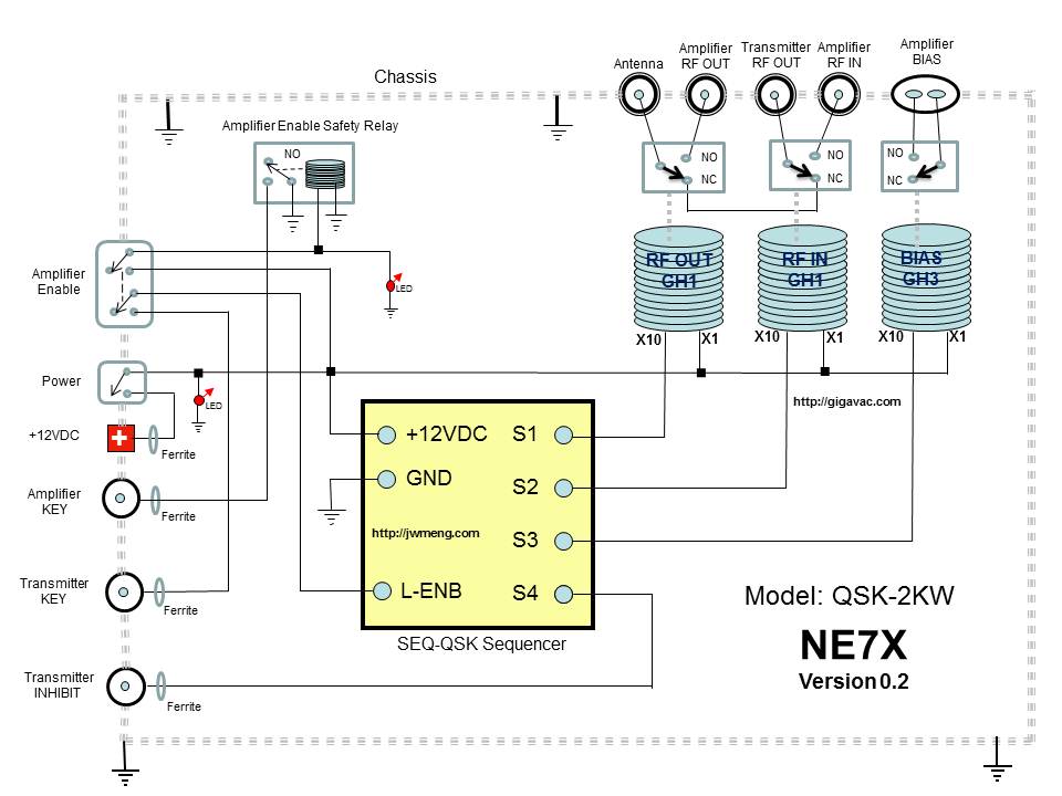
QSK 2KW
The QSK-2KW is an external RF T/R interface device that connects to any RF vacuum tube amplifier. It provides full high-speed RF amplifier T/R switching for CW or digital break-in operation. The QSK-2KW requires a low current keying input, allowing...

SW RF Pre-Amplifier
Amplifying weak radio signals presents the challenge of also amplifying noise. The ability to receive signals is contingent on the level of background noise, which can include man-made interference or static. In this design, the RF signal first encounters a...

50mhz 300w mosfet amplifier circuit
An RF power amplifier is an electronic amplifier used to convert a low-power radio-frequency signal into a larger signal of significant power, typically for driving the antenna of a transmitter. It is optimized for high efficiency, high output power (P1dB)...

Wideband RF Amplifier
This circuit consists of wideband RF amplifiers that utilize current-feedback components such as the THS3202. The THS3202 was selected for its fast slew rate and wide bandwidth. The amplifier voltage gain of this circuit is 20, while the stage voltage...