


Ni-MH battery charger using LT4060
#Ni-MH
#LT4060
#Linear Technologies
#Ni-Cd
#battery charging
#efficient charger
#2 cell
#CHEM pin
#power supply
#energy

Description: This circuit diagram represents a highly efficient Ni-MH battery charger utilizing the LT4060 integrated circuit from Linear Technologies. The circuit can also accommodate Ni-Cd batteries with minor modifications. To charge Ni-Cd batteries, the CHEM pin (pin 12) of the IC should be connected to +Vcc. The configuration is designed to charge two cells connected in series. By adjusting the connections of the SEL0 and SEL1 pins, the circuit can charge up to four batteries in series. For a single cell, both SEL0 and SEL1 pins should be grounded. For two cells, SEL1 should be grounded while SEL0 is connected to Vcc. For three cells, SEL1 is connected to Vcc and SEL0 is grounded. For charging four cells, both SEL0 and SEL1 pins should be connected to Vcc. Additionally, the circuit incorporates temperature-based charge qualification, with an NTC thermistor connected to the NTC pin (pin 11) of the IC acting as the temperature sensor.
The LT4060 integrated circuit is designed specifically for charging nickel-metal hydride (Ni-MH) and nickel-cadmium (Ni-Cd) batteries, providing a robust solution for battery management. The charger operates efficiently by utilizing a constant current and constant voltage charging approach, which is essential for prolonging battery life and ensuring safety during the charging process.
The circuit's flexibility allows for the charging of one to four cells in series, which is facilitated by the SEL0 and SEL1 pins. This configurability makes the LT4060 charger suitable for various applications, including consumer electronics and portable devices. The connections for these pins are critical; grounding both SEL0 and SEL1 is necessary for single-cell charging, while different combinations of Vcc and GND connections enable the charging of two, three, or four cells.
The inclusion of the CHEM pin allows the user to switch between charging Ni-MH and Ni-Cd batteries, enhancing the circuit's versatility. When charging Ni-Cd batteries, connecting the CHEM pin to Vcc modifies the charging parameters to accommodate the specific needs of these cells.
Temperature monitoring is a vital feature of this circuit, as it helps prevent overheating and potential damage to the batteries. The NTC thermistor connected to the NTC pin provides real-time temperature feedback, allowing the LT4060 to adjust the charging current based on the detected temperature. This feature is crucial for maintaining optimal charging conditions, particularly in environments where temperature fluctuations are common.
Overall, the LT4060 battery charger circuit offers a powerful and adaptable solution for charging Ni-MH and Ni-Cd batteries, combining efficiency, safety, and flexibility in one comprehensive design.This is the circuit diagram of a very powerful and efficient Ni-MH battery charger using IC LT4060 from Linear Technologies. In addition to Ni-MH batteries Ni-Cd batteries can be also charged by slightly modifying the circuit.
For charging Ni-Cd batteries connect the CHEM pin (pin12) of the IC to +Vcc. Here the circuit is configured to charge 2 cell s connected in series. By altering the connections of SEL0 and SEL1 pins, upto 4 batteries in series can be charged using this circuit. For charging a single cell, connect SEL0 and SEL1 pins to GND. For charging two cells, connect SEL1 to GND and SEL0 to Vcc. For charging three cells, connect SEL1 to VCC and SEL0 to GND. For charging 4 cells, connect SEL0 and SEL1 pins to VCC. The circuit also features temperature based charge qualification. An NTC thermistor connected at the NTC pin (pin11) of the IC serves as the temperature sensor.
The LT4060 integrated circuit is designed specifically for charging nickel-metal hydride (Ni-MH) and nickel-cadmium (Ni-Cd) batteries, providing a robust solution for battery management. The charger operates efficiently by utilizing a constant current and constant voltage charging approach, which is essential for prolonging battery life and ensuring safety during the charging process.
The circuit's flexibility allows for the charging of one to four cells in series, which is facilitated by the SEL0 and SEL1 pins. This configurability makes the LT4060 charger suitable for various applications, including consumer electronics and portable devices. The connections for these pins are critical; grounding both SEL0 and SEL1 is necessary for single-cell charging, while different combinations of Vcc and GND connections enable the charging of two, three, or four cells.
The inclusion of the CHEM pin allows the user to switch between charging Ni-MH and Ni-Cd batteries, enhancing the circuit's versatility. When charging Ni-Cd batteries, connecting the CHEM pin to Vcc modifies the charging parameters to accommodate the specific needs of these cells.
Temperature monitoring is a vital feature of this circuit, as it helps prevent overheating and potential damage to the batteries. The NTC thermistor connected to the NTC pin provides real-time temperature feedback, allowing the LT4060 to adjust the charging current based on the detected temperature. This feature is crucial for maintaining optimal charging conditions, particularly in environments where temperature fluctuations are common.
Overall, the LT4060 battery charger circuit offers a powerful and adaptable solution for charging Ni-MH and Ni-Cd batteries, combining efficiency, safety, and flexibility in one comprehensive design.This is the circuit diagram of a very powerful and efficient Ni-MH battery charger using IC LT4060 from Linear Technologies. In addition to Ni-MH batteries Ni-Cd batteries can be also charged by slightly modifying the circuit.
For charging Ni-Cd batteries connect the CHEM pin (pin12) of the IC to +Vcc. Here the circuit is configured to charge 2 cell s connected in series. By altering the connections of SEL0 and SEL1 pins, upto 4 batteries in series can be charged using this circuit. For charging a single cell, connect SEL0 and SEL1 pins to GND. For charging two cells, connect SEL1 to GND and SEL0 to Vcc. For charging three cells, connect SEL1 to VCC and SEL0 to GND. For charging 4 cells, connect SEL0 and SEL1 pins to VCC. The circuit also features temperature based charge qualification. An NTC thermistor connected at the NTC pin (pin11) of the IC serves as the temperature sensor.

Changhong DVB-2000 digital satellite receiver switching power supply circuit
The Changhong DVB-2000 digital satellite receiver features a switching power supply circuit. This circuit primarily comprises a power input section, an oscillation switching circuit, and a DC output section. The power input circuit receives 22V AC from a step-down transformer,...

Ni-Cd Battery Automatic Charger
The circuit presented in the above schematic has been designed to charge automatically two series 350mAh "AAA" size batteries. Set the 20KOhms multiturn potentiometer to get a 2.78V on the 3rd pin of the LM311 which is a comparator. So...

AMPLIFIER WITH FORCED EQUILIBRIUM ADAPTOR
Each power supply, whether linear or switching, operates in at least two modes: constant voltage (CV) and constant current (CC). The power supply can function in either mode, with the other serving as a protective mode for both the load...

Self-control digital inverter power supply circuit diagram:1.2V rising to 9V
The circuit does not require a separate power switch or transformation to control the switches on the table. It offers advantages such as low power consumption, stability, reliability, and no impact on instrument accuracy. The transformer T in the circuit...
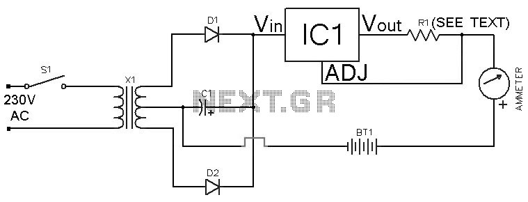
Simple Ni-Cd Battery Charger
This Ni-Cd battery charger is a circuit utilizing the LM317 regulator IC. The design is straightforward and requires minimal components. By adjusting the value of resistor R1 between 1 ohm and 120 ohms, the charging current can be modified from...

250 Watt PC power Supply
Up to 10 A continuous output current, or operation with 50 % ESD and 18 A peak current are possible without a fan if sufficient natural air flow is present and the ambient temperature does not exceed 30 °C. A...
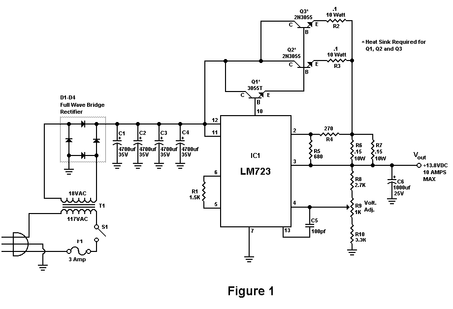
Build A 10 Amp 13.8 Volt Power Supply
Sometimes amateurs like to home-brew their power supplies instead of purchasing one off the shelf at any of the major ham radio retail dealers. The advantage to rolling your own power supply is that it teaches us how they work...

2 watt switching power supply
This compact switching power supply utilizes a Schmitt trigger oscillator to control a switching transistor, which provides current to a small inductor. When the transistor is activated, energy accumulates in the inductor, and this energy is subsequently released into the...

power supply alarm circuit
Most of the power supply failure indicator circuits need a separate power supply for themselves. But the alarm circuit presented here needs no additional supply source. It employs an electrolytic capacitor to store adequate charge, to feed power to the...