



Medium-power-inverter
In this circuit, a CMOS inverter, such as the CD4069, is used to convert the open drain Lx output to a signal suitable for driving the gate of an external P MO...

60Hz-power-inverter
Capacitor C5 and potentiometer R12 determine the frequency of the output signal at pin 3 of IC1, the 555 oscillator. The output signal is differentiated by C3 ...

Zero-error-converter
Single programming resistor Rp provides an output-current range of about six decades.-Note that this resistor"s TC is also a potential source of error; it diss...

Step-up-down-dc-dc-converter
Positive output step-up and step-down de-de converters have a common limitation in that neither can handle input voltages that are both greater than or less th...

Isolated-dc-dc-converter
In this circuit, a TU31 shunt regulator is used to sense the output voltage. The TU31 drives the LED of a 4N28 optocoupler which provides feedback to the MAX64...

Buck-boost-converter
This converter can accommodate wide inputvoltage swings, such as the 8 to 15-V swing typical of a 12-V sealed lead/acid battery. The low battery output indic...

Voltage-to-frequency converter
The D169 serves as a level detector and provides complementary outputs. The op amp is used to integrate the input signal Vin with a time constant of R1C1. The i...

Vlf converter
This converter uses a low-pass filter instead of the usual tuned circuit so the only tuning required is with the receiver. The dual-gate MOSFET and FET used in ...

Simple LF converter
This converter allows coverage from 25 kHz up to 500 kHz. Use short coax from the converter to receiver antenna input...

12V to 9 or 6 v converter
This circuit enables transistorized items such as radio, cassettes, and other electrical devices to be operated from a car"s electrical supply. The table gives ...

Travellers shaver adapter
Many countries have 115 volts mains supplies. This can be a problem if your electric shaver is designed for 220/240 volts only. This simple rectifier voltage do...

Positive input-negative output charge pump
A simple means of generating a low-power voltage supply of opposite polarity from the main supply. Self oscillating driver produces pulses at a repetition frequ...

Flyback converter
A low-current flyback converter is used here to generate ±15 volts at 20 mA from a +5 volt regulated line. The reference generator in the SG1524 is unused wi...

DC-DC regulating converter
Push-pull outputs are used in this transformer-coupled dc-dc regulating converter. Note that the oscillator must be set at twice the desired output frequency as...

400V-60W push-pull DC-DC converter
The TL494 switching regulator governs the operating frequency and regulates output voltage. Switching frequency approximately 100 kHz for the values shown...

Regulated DC-to-DC converter
Low power dc to dc converter obtained by adding a flyback circuit to a square wave oscillator. Operating frequency is 20 kHz to minimize the size of LI and C2. ...

Inverter as high voltage low current source
The circuit is capable of providing power for portable Geiger counters, dosimeter chargers, high resistance meters, etc. The 555 timer IC is used in its multivi...
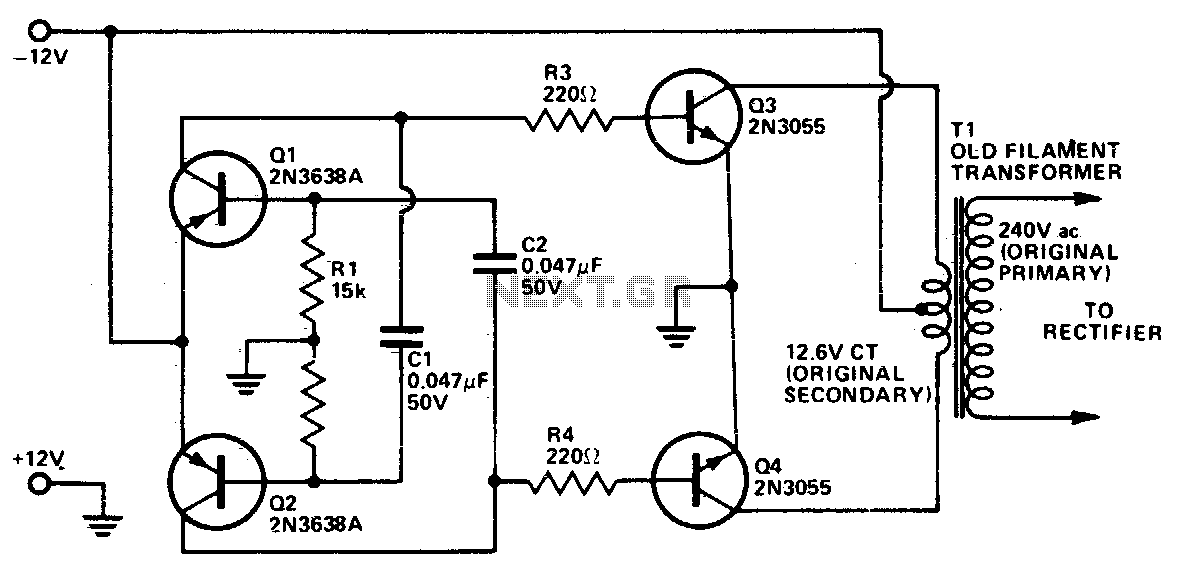
DC-to-DC AC inverter
This inverter uses no special components such as the torodial transformer used in many inverters. Cost is kept low with the use of cheap, readily available comp...
Self oscillating flyback converter
A low-power converter suitable for deriving a higher voltage from a main system rail in an on-board application. With the transformer shown, the operating frequ...

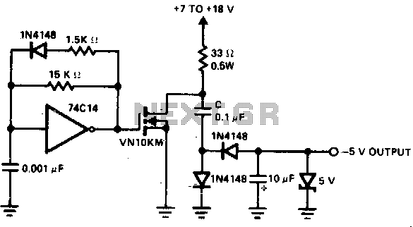
Polarity converter
The capacitor-diode output circuit is used here as a polarity converter to generate a - 5 volt supply from +15 volts. This circuit is useful for an output curre...