



Ac-solid-state-relays
In the case where analog signals are being used as the logic control, hysteresis from a Schmitt-trigger input can be used to prevent haH-wave power output. The...

Low-power-switching-regulator
A simple battery-powered switching regulator provides 5 V outfrom a 9-V source with 80% efficiency and 50 mA output capability. When Q1 is on, its collector vo...

Optoisolated-high-voltage-driver
This circuit takes as an input a signal from a 5-V CMOS logic circuit and outputs a high voltage of the same polarity. The high-voltage supply can be varied fr...

Switching-regulator
The LTC10432 switched-capacitor building block provides nonoverlapping complementary drive to the Ql to Q4 power MOSFETs. The MOSFETs are arranged so that Cl a...

Switching-power-supply
This low-voltage high-current output, sWitching de power supply is running off the 220-Vac input. In this circuit, an ST2 diac relaxation oscillator, Q3, Cl, a...

Ac-relay
When zero voltage switching is not required, methods of providing this function are illustrated. The lowest parts count version of a solid-state relay is an op...

Dc-latching-relay
The HllC supplies the de latching relay function and reverse polarity blocking, for currents up to 300 mA, depending on ambient temperature. For de use, the ga...
Solid-state-relay
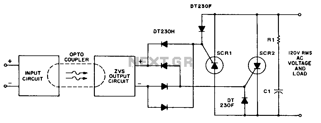
A higher Iiue voltage can be used if the diode, varistor, ZVS, and power thyristor settings are at compatible levels. ...

Normally-open-and-closed-relays
The phototransistor and photodarlington couplers act as de relays in saturated switching at currents up to 5 mA and 50 mA, respectively. When higher currents o...
Normally-closed-half-wave
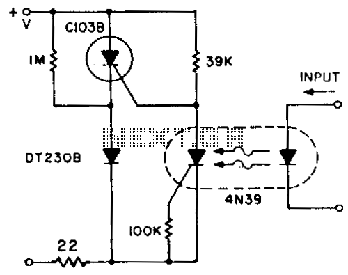
A normally closed contact circuit that provides zero-voltage switching is designed around the 4N39 SCR optocoupler. ...

Triggering-scr-series
Snubber circuit R2C2, as shown, might be necessary since Rl and Cl are tailored for optimized triggering and not for dV!dt protection. Fiber-optic pairs can be...

Zero-voltage-switching-circuits
This circuit is effective for lamp and heater loads. Some circuits driving reactive loads require integral cycling and zero-voltage switching-when an identical...

High-voltage-ac-switcher
A basic circuit to trigger an SCR is shown in Fig. 67 -lA. This circuit has the disadvantage that the blocking voltage of the photon-coupler output device dete...

Burst-power-control
Industrial applications sometimes require that power be only briefly applied to a load following the closure of a switch, such as a microswitch or foot switch....

Photoelectric-ac-power-switch
For a dark photocell, high resistance, the vohage across the diac rises rapidly with the line voltage due to the current through C 1, triggering the diac ear...

Laser-diode-pulsers
The laser diode·pulser is a simple drive circuit capable of driving the laser diode with 10-A, 20-ns pulses. For a 0.1 % duty cycle, the repetition rate wil...

Phase-control
This circuit uses a PUT for phases control of an SCR. The relaxation oscillator formed by Q2 provides conduction control of Ql from 1 to 7.8 ms or 21.6° to ...

Who-is-first
Using two SCRs, this control circuit is designed to lock out the other SCR when one has been triggered, so only one lamp will light. Indicator lamp Il is con...

Totem-pole-driver-with-bootstrapping
When driving MOSPOWER in a totem-pole output configuration, it is necessary to have the gate voltage 10 to 15 V positive with respect to the source in order ...
Line-synchronized-driver
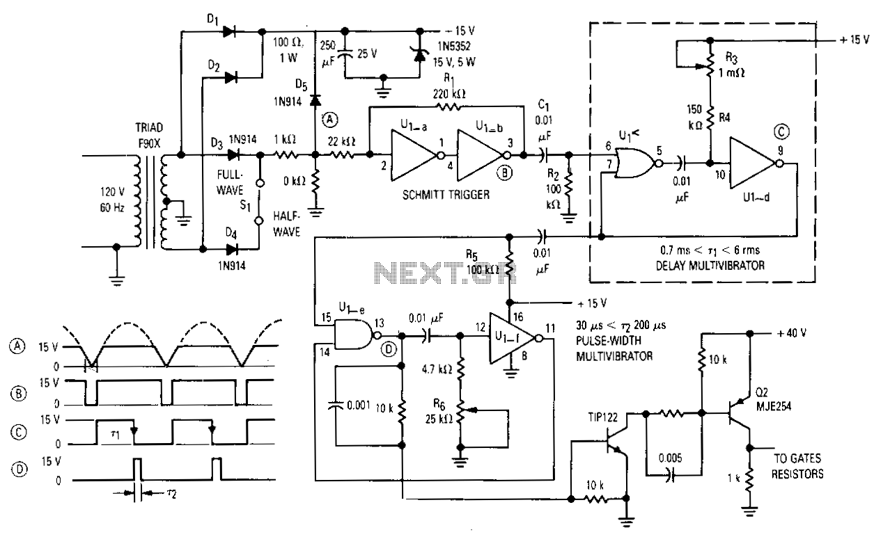
The gate drive that phase controls the four parallel SCRs is accomplished with complementary MOS hex gate MC14572 and two bipolar transistors. This adjustable ...