Applied Voltage Controlled Oscillators
1. Definition and Key Properties
1.1 Definition and Key Properties
Applied Voltage Controlled Oscillators (VCOs) are integral components in numerous electronic systems. Primarily, they convert an input voltage signal into an oscillating output frequency, making them vital in applications such as phase-locked loops (PLLs), frequency modulation, and signal generation. This versatility is what makes understanding their definition and key properties essential for advanced practitioners in electronics and related fields.
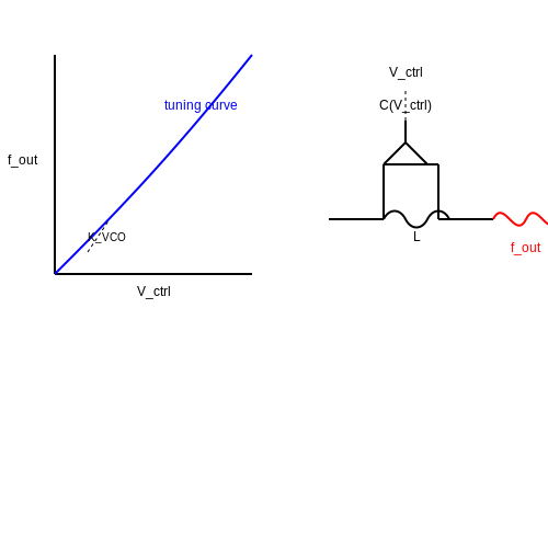
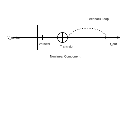
A VCO operates on the principle that the frequency of its output signal is directly proportional to the input voltage. The basic structure often includes a nonlinear component, such as a varactor diode or a transistor, configured to create a feedback loop. This feedback, alongside the control voltage, determines the oscillation frequency. The relationship between the control voltage (Vcontrol) and the output frequency (fout) can be expressed mathematically as:
where k is a proportionality constant that defines the sensitivity of the VCO, and f0 is the frequency offset when the control voltage is at a specific reference level. For instance, operational amplifiers (op-amps) and transistors can be configured in different topologies (like relaxation oscillators or more sophisticated Colpitts and Clapp circuits) to achieve the desired frequency response.
Key Properties of VCOs
Understanding the essential properties of VCOs not only aids in their design but also helps in predicting their performance in practical applications. Below are some key properties that significantly impact their functionality:
- Tuning Range: This is the range of frequencies over which the oscillator can operate, dictated by the design of the circuit and the components involved. A wider tuning range allows for greater flexibility in applications, such as variable-frequency transmitters or receivers.
- Linearity: Linearity refers to how well the frequency of the output signal follows the input control voltage. Ideally, the relationship should be linear; however, practical VCOs exhibit some nonlinearities that are crucial to account for in high-performance applications.
- Phase Noise: This attribute assesses the purity of the output signal frequency, quantifying the short-term fluctuations in the signal phase. Phase noise is crucial for communication systems where signal integrity is paramount.
- Temperature Stability: VCO performance can be sensitive to temperature fluctuations. Understanding how temperature affects the components will lead to greater reliability in real-world applications.
- Power Consumption: Lower power consumption in VCOs results in less heat generation, maximizing performance, especially in portable electronic devices.
The practical relevance of VCOs extends to an array of systems, including but not limited to telecommunications, audio synthesis, and clock generation in digital circuits. By incorporating principles of signal processing and modulation, VCOs enable engineers to develop advanced communication systems, where efficiency and precision are crucial.
To summarize, VCOs serve as foundational elements in modern electronics, enabling a range of functions that hinge on their ability to transform voltage levels into oscillating frequencies. Delving into their intricate properties enhances both theoretical understanding and practical capabilities in the field.
1.2 Operating Principles
Voltage Controlled Oscillators (VCOs) are crucial components in a variety of electronic systems, especially in frequency synthesis and modulation applications. To unravel the functionality of VCOs, it is imperative to understand their operating principles. At the core of a VCO's operation is the relationship between the applied voltage and the frequency of the output signal.
A VCO is essentially a type of oscillator that produces a periodic output signal whose frequency varies with an input control voltage. The fundamental mechanism involves the manipulation of reactive components—typically capacitors and inductors—in an oscillator circuit. The most common types of VCOs use LC circuits or phase-locked loop (PLL) architectures to achieve this frequency modulation.
LC Oscillator Fundamentals
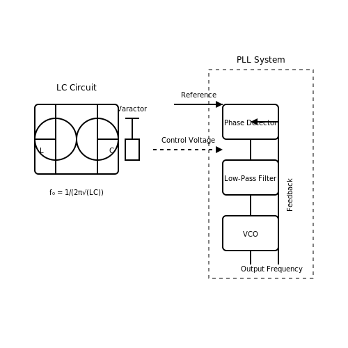
One of the simplest forms of VCOs is the LC oscillator, which relies on an inductor (L) and a capacitor (C) to set the oscillation frequency. The resonant frequency of such an LC circuit can be expressed as:
Where:
- f0 is the oscillation frequency in Hertz (Hz).
- L is the inductance in Henries (H).
- C is the capacitance in Farads (F).
In a typical VCO setup, two control mechanisms can adjust the effective capacitance or the inductance of the circuit. The most prevalent method is through voltage-controlled variable capacitors, known as varactors. By applying a voltage across a varactor, its capacitance changes, thereby altering the resonant frequency. This is known as the capacitive tuning method.
Phase-Locked Loop (PLL) Configurations
Another common architecture for implementing VCOs is through the use of phase-locked loops. A PLL generally consists of a phase detector, a voltage-controlled oscillator, and a low-pass filter. The phase detector compares the phase of the input signal with that of the oscillator. When there is a phase difference, it generates an error signal that influences the VCO through the low-pass filter. The resultant output frequency thus adjusts to minimize the phase difference, contributing to frequency stability and robustness.
The output frequency f of a PLL can typically be expressed as:
Where N is the division ratio and fref is the reference frequency fed into the PLL. This dynamic adjustment effectively endows VCOs with capabilities for fine-tuning frequencies across a range of applications, encompassing communications, signal processing, and data conversion.
Practical Relevance and Applications
The versatility of VCOs positions them as pivotal components in a myriad of applications. In communication systems, they are used in modulating signals, frequency-hopping, and demodulating signals. Furthermore, in synthesizers, they serve a vital role in generating audio frequencies, making them indispensable in electronic music creation. The precision offered by voltage-controlled oscillators also enhances the performance of clock generators and timers in digital circuits.
Furthermore, advancements have led to the integration of VCOs in RF and microwave technologies, enabling improved signal integrity in wireless communications. As technology progresses, the demand for high-frequency, low-noise VCOs continues to grow, urging industries to innovate in designs that can meet stringent specifications for modern circuitry.
1.3 Types of Voltage Controlled Oscillators
Voltage Controlled Oscillators (VCOs) are pivotal components in a wide array of electronic systems, serving primarily for generating variable frequency signals controlled by an input voltage. In this segment, we will explore several distinct types of VCOs, each exhibiting unique characteristics, advantages, and typical applications.
Analog Voltage Controlled Oscillators
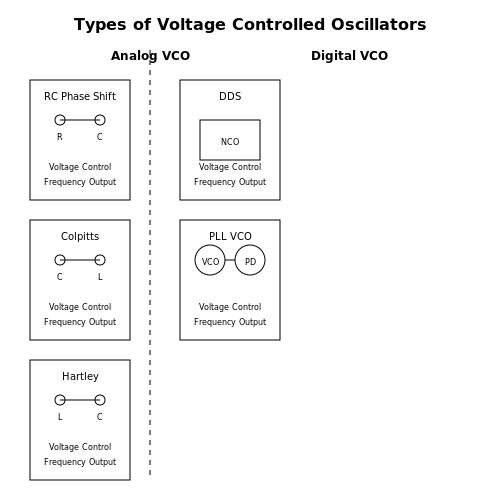
Analog VCOs are characterized by their continuous output frequency modulation in response to the analog input voltage. The most common types include:
- RC Phase Shift Oscillator: Utilizing resistors and capacitors to generate oscillations, the frequency can be modulated by changing the resistance or capacitance values. These are simple and cost-effective, making them suitable for low-frequency applications.
- Colpitts Oscillator: This oscillator is composed of a combination of capacitors and an inductor. By varying the capacitance through a voltage-controlled device, the oscillation frequency can be adjusted. Colpitts oscillators are often employed in RF applications due to their stability.
- Hartley Oscillator: Similar to the Colpitts, the Hartley oscillator utilizes inductive components and is favored for its simplicity in adjusting frequency through variable inductances.
Analog VCOs are instrumental in applications such as FM transmitters, tone generators, and frequency synthesizers, illustrating their versatility and utility in real-world scenarios.
Digital Voltage Controlled Oscillators
In contrast, digital VCOs operate using discrete time signals. They often employ phase-locked loops (PLLs) to derive frequencies from a stable reference clock. The classifications of digital VCOs include:
- Direct Digital Synthesis (DDS): A sophisticated method that generates precise waveforms using digital techniques. DDS is highly versatile, allowing for rapid frequency changes and waveform shaping without significant analog components.
- Phase-Locked Loop (PLL) VCO: A design that integrates a variable frequency oscillator within a PLL circuit, enabling frequency locking to a reference signal. This configuration is prevalent in applications requiring high precision, such as telecommunications and signal processing.
While digital VCOs can demand more complex circuitry, their precision and ability to produce stable frequencies make them invaluable in modern electronics, particularly in communications systems.
Applications and Practical Considerations
The choice between analog and digital VCOs typically hinges on the application's requirements regarding frequency stability, tuning range, and cost. For instance, analog VCOs are favored in environments where simplicity and low-cost solutions are prioritized, whereas digital VCOs dominate in high-performance applications requiring exact frequency control and stability.
Real-world applications showcase the efficacy of both VCO types. Analog VCOs find their way into simple tone generators and radio systems, while digital VCOs are mainstream in advanced communication systems, digital synthesizers, and intricate radar systems. Understanding the underlying principles and differentiations between these types of VCOs can empower engineers and researchers to make informed decisions that align with their project goals.
2. Component Selection
2.1 Component Selection
The heart of a Voltage Controlled Oscillator (VCO) lies in its components, each of which plays a crucial role in determining the performance and efficiency of the oscillator circuit. The selection of these components is not simply a matter of availability or cost; it is an intricate process that demands a firm understanding of their functional properties, characteristics, and the specific requirements of the application. To initiate this discussion, one must consider the primary components involved in VCO design, namely the voltage-controlled element, feedback network, and amplification stage. Each component requires a meticulous evaluation to ensure optimal operation.Key Components of a VCO
Voltage-Controlled Element: The most common elements used as voltage-controlled components are varactor diodes, operational amplifiers, and transistors. Varactor diodes, or varicaps, are particularly advantageous due to their ability to vary capacitance based on the applied voltage. This property is critical for tuning the frequency output of the VCO. When selecting a varactor diode, consider parameters such as capacitance range, series resistance, and tuning sensitivity. Higher tuning sensitivity translates to a smaller voltage range required for a significant change in frequency, which can be critically beneficial in achieving fine frequency adjustments. Feedback Network: The feedback network helps to stabilize the oscillation frequency and is often made of resistors, capacitors, and sometimes inductors. The choice of components here influences the circuit's overall Q factor, which is a measure of the sharpness of the oscillation peak. A higher Q factor results in a more stable oscillation at a defined frequency, which is essential for applications such as RF transmission. When configuring the feedback loop, you will want to carefully choose the values of resistors and capacitors. This requires numerical simulation and an understanding of the desired frequency range and bandwidth to achieve functionally acceptable results. Amplification Stage: The amplification stage can utilize operational amplifiers or transistors, depending on the desired gain and linearity. In designing this stage, consider the frequency response, noise figure, and power consumption of the amplifier. Operational amplifiers with low noise and high slew rate are usually preferred in applications requiring high precision.Real-World Applications
In real-world applications, the choice of components can significantly influence the efficiency and effectiveness of VCOs. For instance, in phase-locked loops used in communication systems, a well-designed VCO can markedly enhance signal integrity and minimize jitter, leading to improved data rates. In contrast, suboptimal component choices might result in noisy signals that undermine performance. Moreover, the emergence of advanced materials has provided new avenues for component selection. For example, silicon-based MEMS resonators have gained traction due to their small size and low power requirements, making them suitable for fit-in-chip applications. Exploring such modern materials and their characteristics can lead to innovative and more efficient designs. A comprehensive understanding of components and their interactions within the VCO framework ultimately paves the way for achieving high-performance oscillators suited for a wide range of engineering applications. This foundation will be instrumental as we delve deeper into the operational principles and design techniques of applied voltage-controlled oscillators in the following sections.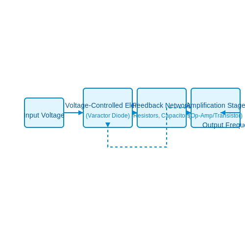
2.2 Circuit Topologies
Applied Voltage Controlled Oscillators (VCOs) are fundamental components in various electronic systems, serving applications that range from signal processing to communications and instrumentation. The design of these oscillators often hinges on the choice of circuit topology, as this can significantly influence their performance characteristics, including frequency stability, linearity, and tuning range. In this section, we will delve into some commonly used circuit topologies for VCOs, emphasizing their principles, configurations, and real-world relevance.Understanding the Circuit Topologies
A voltage-controlled oscillator generally functions by producing a periodic output signal whose frequency can be adjusted using an applied control voltage. The choice of circuit topology can dictate the oscillator's performance regarding factors such as phase noise, frequency drift, and output waveform shape. Below, we outline several prevalent circuit topologies for VCOs.1. Colpitts Oscillator
The Colpitts oscillator is a popular topology for implementing VCOs due to its simplicity and robustness. Typically configured using a bipolar junction transistor (BJT) or a field-effect transistor (FET), this topology leverages a combination of capacitors and inductors to establish oscillation conditions. The basic structure consists of:- A transistor configured in a common emitter or common source mode.
- A tank circuit, which includes two capacitors (C1 and C2) and an inductor (L), to set the oscillation frequency.
2. Hartley Oscillator
Similar to the Colpitts oscillator, the Hartley oscillator is characterized by its LC tank circuit, but it employs a different configuration of inductors and capacitors. In this topology, the frequency is determined by two inductors (L1 and L2) and one capacitor (C). The fundamental frequency expression is given by:3. Ring Oscillator
Ring oscillators are distinctive in that they consist of an odd number of inverters (or buffer stages) connected in a loop. The oscillation frequency is substantially influenced by the propagation delay across each stage. Although typically employed in integrated circuits, they represent an excellent choice for very high-frequency applications due to their minimal component requirements. The oscillation frequency can be expressed as:4. Phase-Locked Loop (PLL) based VCOs
PLLs are critical in applications requiring precise frequency synthesis and stability. A VCO within a PLL generates an output frequency that is phase-locked to a reference frequency. This topology integrates feedback mechanisms with components such as phase detectors and low-pass filters to stabilize the output frequency effectively. In practical implementations, the output frequency of a VCO in a PLL is adjustable based on the control voltage—typically generated from a phase comparator. This flexibility allows for efficient tuning across broad frequency bands, making PLL-based VCOs ideal for communication systems and frequency modulation.Conclusion
The selection of a circuit topology for voltage-controlled oscillators heavily influences performance metrics. Each topology provides unique advantages, making them suitable for specific applications. The Colpitts and Hartley oscillators stand out for their simplicity, while ring oscillators excel in high-frequency environments, and PLL configurations offer superior stability and tuning capability. Understanding these configurations is essential for engineers and researchers in harnessing the full potential of VCOs in their respective domains. The next section will explore the various modulation techniques applied in conjunction with these VCO topologies, broadening our understanding of their role within comprehensive electronic systems.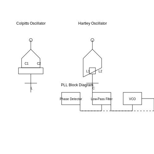
2.3 Stability and Tuning Range
Voltage-controlled oscillators (VCOs) play a crucial role in various electronic applications, ranging from signal generation in communication systems to clock generation in digital circuits. Two significant characteristics that dictate their performance are stability and tuning range. Understanding these concepts ensures that VCOs operate efficiently across different applications, making them essential for engineers and researchers alike.
Stability of Voltage Controlled Oscillators
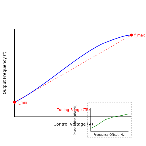
The stability of a VCO refers to its ability to maintain consistent frequency output despite variations in environmental conditions, component tolerances, and supply voltage fluctuations. It can impact the performance of the overall system where the VCO is being employed. The Phase Noise of a VCO is an important measure of its stability, representing the short-term frequency fluctuations that occur over time.
Phase noise tends to be quantified in decibels relative to the carrier (dBc/Hz). A VCO with low phase noise is preferable in applications like frequency modulation (FM) and phase-locked loops (PLLs), where signal integrity is critical. To improve the stability, designers often manipulate various parameters such as biasing conditions and component selection.
Mathematical Explanation of Phase Noise
Phase noise can be expressed as:
In this equation, L(f) represents the phase noise in dBc/Hz, and Sφ(f) is the spectral density of the phase fluctuations at frequency f. Understanding this relationship helps in designing VCOs with desired stability characteristics.
Tuning Range of Voltage Controlled Oscillators
The tuning range is defined as the frequency span over which a VCO can effectively oscillate when varying its control voltage. A larger tuning range allows a VCO to be used in a wider variety of applications. However, there are trade-offs in achieving both a wide tuning range and enhanced stability.
Typically, the tuning range can be expressed as a percentage of the center frequency fc:
Here, fmax and fmin are the maximum and minimum frequencies within the tuning range, respectively. Designers need to optimize the circuit design, including the choice of reactive components and the non-linear characteristics of the active device used in the VCO, to achieve a desired tuning range while maintaining stability.
Practical Considerations
In practical applications, VCOs are often integrated into larger systems, which imposes additional constraints on their performance. For instance, in phase-locked loop (PLL) designs, the VCO must exhibit low phase noise to ensure reliable locking and tracking of input frequencies. The tuning range must also be compatible with the reference frequency of the PLL to operate effectively.
In conclusion, achieving the optimal balance between stability and tuning range is paramount in VCO design. Engineers must carefully consider different design strategies and solutions to address these two interrelated aspects, ensuring the oscillator meets the specific requirements of its application.
3. Communication Systems
3.1 Communication Systems
In the realm of electronics, Voltage Controlled Oscillators (VCOs) play an integral role, especially within communication systems. These devices leverage the principle of varying voltage levels to produce oscillating signals, fundamentally essential for transmitting information over various mediums. An understanding of how VCOs operate within these systems unveils their significant advantages and functional diversity.Fundamentals of Voltage Controlled Oscillators
A Voltage Controlled Oscillator generates a periodic output signal—commonly sinusoidal—whose frequency is a function of the input voltage. This frequency modulation allows VCOs to adjust the rate of oscillation based on control voltage, thereby enabling dynamic performance tailored for communication tasks. The output frequency \( f \) can be expressed as:Application in Communication Systems
In communication systems, VCOs are vital in numerous applications such as phase-locked loops (PLLs), frequency modulation (FM), and signal generation. They ensure accurate and reliable signal generation and modulation, which are critical for effective data transfer. Phase-Locked Loops (PLLs) are a prime example where VCOs find extensive utility. In a PLL, the VCO generates a frequency that is adjusted based on the phase difference between the output signal and the reference signal. The feedback mechanism enables phase synchronization, essential for data recovery and signal integrity in systems like radio transmitters and receivers. Transitioning from basic signal generation to modulation techniques, VCOs also serve in Frequency Modulation (FM). FM encodes information in the frequency of the carrier wave, providing a robust and noise-resistant signal. The ability of VCOs to switch frequencies rapidly makes them ideal for FM applications, which is widely utilized in radio broadcasting and telecommunications.Advantages and Challenges
The primary advantage of implementing VCOs in communication systems lies in their versatility and responsiveness. The rapid adjustability allows for efficient bandwidth usage, essential in modern communication networks that operate with limited frequency resources. However, VCOs also face inherent challenges, including sensitivity to temperature variations and power supply fluctuations, which can affect stability and performance. To enhance VCO performance, various compensation techniques such as temperature compensation circuits and high-quality components are employed to mitigate the adverse effects of environmental conditions. For instance, a design might integrate a temperature sensor that adjusts the control voltage in response to temperature changes, maintaining consistent oscillation frequencies.Conclusion
Overall, Voltage Controlled Oscillators are indispensable in the architecture of communication systems, enabling frequency modulation and dynamic signal processing while offering substantial advantages in flexibility and efficiency. As technology advances, the integration of VCOs with digital control systems is likely to enhance their performance further, paving the way for new applications in upcoming generations of communication technologies.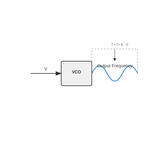
3.2 Signal Processing
When discussing Applied Voltage Controlled Oscillators (VCOs), an essential aspect is their interaction with signal processing. This interaction involves the manipulation of signals generated by VCOs to meet desired specifications and serve functionality in various applications ranging from telecommunications to electronic instrumentation. A profound understanding of signal processing in this context will enable engineers and researchers to leverage VCOs in innovative ways.Understanding the Role of VCOs in Signal Processing
At its core, a VCO is a circuit that generates an oscillating signal whose frequency is directly controlled by an input voltage. This feature is particularly useful in frequency modulation applications where the frequency of the output signal needs to adapt dynamically according to varying input conditions. The ability to produce a wide range of frequencies makes VCOs indispensable in synthesizers, phase-locked loops (PLLs), and other modulation schemes. In practical terms, when a varying control voltage is applied to a VCO, the output frequency can be described using the equation:Signal Modulation Techniques
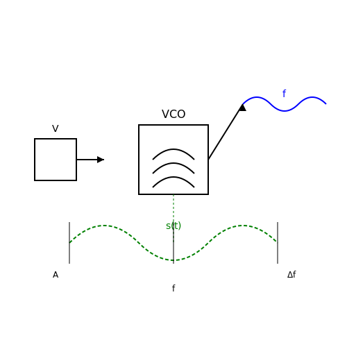
VCOs can be integrated into various modulation schemes. One prominent method is Frequency Modulation (FM). In FM, the information signal modulates the frequency of the VCO output, allowing for robust transmission over varying conditions. The output signal \( s(t) \) can be expressed as:Demodulation Challenges
One of the critical challenges in utilizing VCOs within signal processing is demodulation, particularly in recovering the original signal from an FM modulated waveform. Various demodulation techniques exist—such as phase-locked loops (PLLs) and quadrature demodulation—which can be integrated into receiver designs to ensure accurate reconstruction of the transmitted signal. Using a PLL, for instance, the VCO in the loop generates a signal at a frequency that locks onto the frequency of the incoming modulated signal, providing a stable output for further processing.Applications in Real-World Systems
The practical applications of VCOs within signal processing are immense. These devices are crucial in:- Telecommunications: VCOs are employed in frequency synthesizers to create stable carrier waves for data transmission.
- Signal Generators: They serve as sources for testing various electronic devices by producing a range of frequencies.
- Radar Systems: In radar technology, VCOs contribute to signal processing for accurate target detection and tracking.
- Audio Processing: Synthesizers utilize VCOs for generating musical tones and sounds in electronic music production.
3.3 Frequency Synthesis
The process of frequency synthesis is a critical technique used in modern electronics, leveraging voltage-controlled oscillators (VCOs) to produce a range of frequency outputs from a single reference frequency. In this section, we explore the underlying principles of frequency synthesis, examining how VCOs facilitate the generation of different frequencies while maintaining precision and stability. To begin, let's consider what frequency synthesis entails. At its core, frequency synthesis is the creation of specific frequencies needed for communication, radar, direct digital synthesis (DDS), or other applications where precise timing is essential. One of the most compelling advantages of frequency synthesis using VCOs is the ability to generate frequency outputs that are integer multiples or fractions of a fundamental frequency.Understanding VCOs in Frequency Synthesis
A VCO is a type of oscillator whose output frequency is controllable by an input voltage. This characteristic allows for rapid and flexible adjustments, making VCOs versatile components in synthesizers. In typical configurations, a phase-locked loop (PLL) is used in conjunction with a VCO to create a stable output frequency. The PLL compares the output of the VCO with a reference frequency and adjusts the control voltage accordingly, resulting in a consistent and accurate output frequency. The effectiveness of frequency synthesis can be understood better with the following equation, which illustrates the relationship between the control voltage and the frequency output of the VCO:Applications of Frequency Synthesis
The practical applications of frequency synthesis are vast and impactful in various fields. Here are a few noteworthy examples:- Communications Systems: Frequency synthesis is integral to generating precise frequency carriers in radio transmitters and receivers, enabling effective data transmission over long distances.
- Signal Generators: VCOs are employed in test equipment to generate any frequency signal needed for system testing and analysis.
- Radar Systems: Frequency synthesizers create high-resolution signals that enhance detection accuracy and target discrimination in radar applications.
- Digital Signal Processing: DDS techniques utilize frequency synthesis to generate arbitrary waveforms, essential in audio signal generation and telecommunications.
Conclusion
In conclusion, frequency synthesis using voltage-controlled oscillators is a powerful method that enhances the capability to generate precise frequencies across different applications. By manipulating the control voltage in conjunction with the principles of phase-locked loops, engineers can create systems that are both versatile and reliable. As we delve deeper into VCO technologies, understanding their impact on frequency synthesis becomes paramount in designing advanced electronic systems. This knowledge sets a foundation for exploring more intricate aspects of VCO behavior and the challenges that engineers face in frequency synthesis. As we proceed, we will investigate the linearity and stability of VCO outputs, essential considerations when designing circuits that rely on precise timing and frequency accuracy.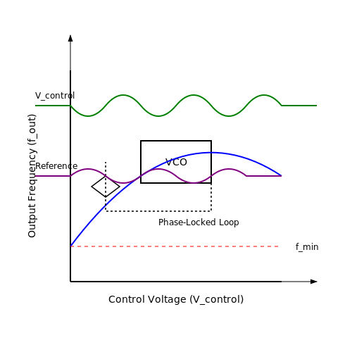
4. Phase Noise Characteristics
4.1 Phase Noise Characteristics
Phase noise is an intrinsic property of oscillators, including voltage-controlled oscillators (VCOs) that impacts their phase stability and spectral purity. In practical applications, phase noise is a critical parameter for performance, particularly in communication systems and signal processing where timing precision is imperative.
To comprehend the implications of phase noise, it is essential first to understand its origins and manifestations in VCOs. Phase noise arises from various factors, including fluctuations in the supply voltage, temperature variations, and, notably, intrinsic noise from active components such as transistors or operational amplifiers. These fluctuations can lead to random phase shifts, degrading the signal quality and coherence.
Understanding Phase Noise in VCOs
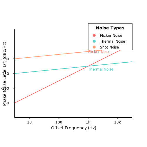
The phase noise of a VCO can be quantified as a power spectral density (PSD) typically expressed in dBc/Hz at a specific offset frequency from the carrier frequency:
Here, \( L(f) \) is the phase noise level, \( S_{\phi}(f) \) is the phase noise power spectral density, and \( P_{0} \) is the total output power of the carrier. The phase noise plot usually depicts how \( L(f) \) varies with offset frequency, providing insight into the oscillator's stability.
Sources of Phase Noise
Key contributors to phase noise in VCOs include:
- Flicker Noise: This low-frequency noise is dominant at low offset frequencies, resulting from the resistive and capacitive components in the circuit.
- Thermal Noise: Generated by the thermal agitation of charge carriers, thermal noise contributes to phase fluctuations, dependent on biasing conditions.
- Shot Noise: Present in bipolar junction transistors, shot noise can affect VCO output phase, particularly in high-frequency applications.
- Phase Jitter: As random variations in signal timing, phase jitter can also affect the overall phase noise characteristics of oscillators.
Implications and Applications
The degree of phase noise can significantly affect applications requiring high timing accuracy, such as:
- Communications: In systems like phase-locked loops (PLLs) and spread spectrum systems, reduced phase noise is paramount for data integrity.
- Radar Systems: High precision is critical in radars; phase noise may cause range and velocity measurement errors.
- Atomic Clocks: For timekeeping, minimizing phase noise directly correlates to improved frequency stability, enhancing the clock’s accuracy.
Understanding and controlling the phase noise characteristics of VCOs can lead to the development of more stable systems, ultimately yielding better performance in advanced applications.
4.2 Frequency Stability
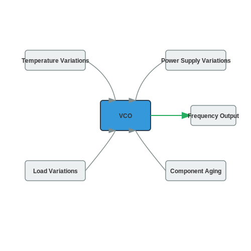
Frequency stability is a critical aspect of Voltage Controlled Oscillators (VCOs), directly impacting their performance in practical applications such as telecommunications, signal processing, and frequency synthesis. Understanding the factors that contribute to frequency stability can significantly enhance the design and application of VCOs in various advanced engineering contexts. At its core, frequency stability in a VCO indicates how consistent the output frequency remains over time and under varying environmental conditions. A stable frequency output is vital for applications like phase-locked loops (PLLs), where frequency deviation can lead to loss of synchronization, resulting in degraded signal integrity or even complete system failure. Key Factors Influencing Frequency Stability Several factors influence the frequency stability of VCOs, including:- Temperature Variations: Temperature changes can lead to frequency drift due to changes in the electronic components and the properties of the dielectric materials used in the oscillator circuit.
- Power Supply Variations: Fluctuations in the power supply can affect the operation of the oscillator, causing unwanted variations in the output frequency.
- Component Aging: Over time, the physical and electrical properties of the components in the VCO may change, leading to frequency instability.
- Load Variations: Changes in the load connected to the oscillator can induce frequency shifts, necessitating careful load management for applications requiring high stability.
Measuring Frequency Stability
Measurement techniques for assessing frequency stability include: 1. Phase Noise Measurement: Utilizing spectrum analyzers configured for phase noise measurement provides a quantitative metric of the stability, typically expressed in decibels relative to the carrier frequency (dBc/Hz) at defined offset frequencies. 2. Frequency Drift Measurement: This involves monitoring the frequency output over extended periods under controlled operating conditions to observe how much the frequency deviates from its nominal value. The importance of each technique is heavily dependent on the specific application of the VCO. For instance, in telecommunications, phase noise may be more critical to maintain data integrity during high-speed transmission.Improving Frequency Stability
Several approaches can be employed to enhance frequency stability, including:- Temperature Compensation: Implementing temperature compensation strategies, such as the use of temperature coefficients or compensating circuits, can help maintain stable operation across different temperatures.
- Regulated Power Supply: Using a well-regulated power supply minimizes frequency shifts due to power supply variations, thereby improving stability.
- High-Quality Components: Selecting precision components with low drift specifications reduces the impact of component aging and variations.
- Feedback Control Systems: Employing feedback mechanisms can actively correct frequency deviations, providing real-time stabilization in response to external perturbations.
4.3 Output Waveform Quality
In the realm of Applied Voltage Controlled Oscillators (VCOs), the quality of the output waveform is a critical aspect that influences the overall performance of electronic systems. This section addresses the parameters that define waveform quality, analysis techniques, and its implications in various applications such as communication systems and signal processing.
Understanding Waveform Quality
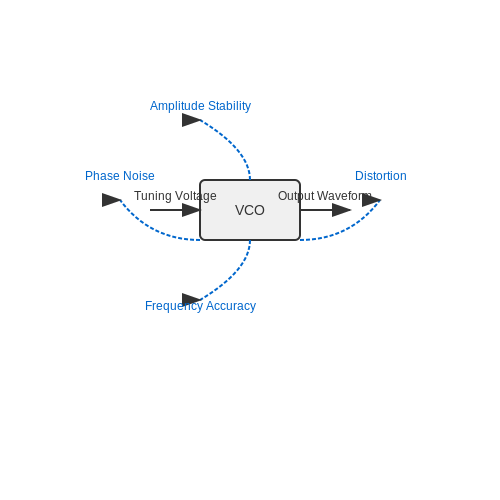
Waveform quality in VCOs encompasses several key factors, primarily:
- Amplitude stability: Refers to the consistency of the output voltage levels.
- Frequency accuracy: The precision at which the output frequency matches the intended design specifications.
- Phase noise: Represents the short-term frequency variations that can affect signal integrity.
- Distortion: The deviation of the output waveform from the ideal shape, which may introduce unwanted harmonic content.
- Rise and fall times: Speaks to how quickly the waveform transitions between voltage levels, which affects the bandwidth.
Amplitude Stability and Distortion
The amplitude stability is particularly essential in applications such as phase-locked loops (PLLs), where variations in signal amplitude could lead to erroneous locking conditions. Furthermore, distortion, often quantified in Total Harmonic Distortion (THD), becomes critical in high-fidelity audio applications. The relationship can be quantitatively expressed as:
where \( V_1 \) is the fundamental frequency voltage and \( V_n \) represents the voltages of the nth harmonic components. This relationship emphasizes the need for careful design to minimize harmonic generation, ensuring output fidelity.
Frequency Accuracy and Phase Noise
Frequency accuracy is paramount when the VCO is employed in systems that require strict adherence to frequencies, such as radio transmitters and receivers. The precision of the frequency can be evaluated by examining the impact of tuning voltage levels on the output frequency. The frequency deviation \( \Delta f \) can be characterized by:
where \( K_v \) is the frequency sensitivity in Hz/V and \( \Delta V_t \) is the change in tuning voltage. Low phase noise is equally crucial, particularly in communication applications, impacting the signal-to-noise ratio (SNR). The phase noise is typically assessed using a phase noise measurement system that quantifies the undesired stability fluctuations in frequency.
Real-World Applications of Waveform Quality
Understanding and optimizing the quality of the waveform output from VCOs has substantial implications in various fields:
- Telecommunications: Where signal integrity is crucial for modulation schemes and frequency synthesis.
- Instrumentation: In devices that require precise timing and frequency generation.
- Consumer Electronics: Such as high-end audio devices where distortion and fidelity are of primary concern.
Innovative techniques are pursed in modern VCO designs to improve output quality, including temperature compensation systems and advanced feedback mechanisms. The balance between achieving low phase noise and distortion while maintaining amplitude stability and accurate frequency remains a vital area of research in electronic engineering.
In summary, the output waveform quality of applied voltage-controlled oscillators directly influences the performance across a wide array of electronic applications. An in-depth understanding of the underlying principles and mathematical modeling empowers engineers and researchers to innovate and optimize this essential component of electronic systems.
5. Common Failure Modes
5.1 Common Failure Modes
Introduction to Failure Modes
In the realm of applied voltage-controlled oscillators (VCOs), understanding potential failure modes is crucial for both design and troubleshooting processes. A VCO typically operates by varying the frequency of its output signal in response to an applied voltage, and the performance can be compromised by various factors. Recognizing these failure modes allows engineers to design more robust systems, improving reliability in applications such as telecommunications, signal processing, and even automotive electronics.Thermal Issues
One significant failure mode in VCOs stems from thermal effects. As the circuit operates, loss mechanisms such as conduction and switching can lead to increased temperatures within the VCO components. These excessive temperatures can shift device characteristics and cause frequency drift or instability. The relationship between temperature and frequency can often be described using the temperature coefficient of frequency ($$TC_F$$). The equation for a typical oscillator might reveal that:Supply Voltage Variations
Another common failure mode involves fluctuations in the supply voltage itself. VCO performance is often sensitive to input voltage levels, making it imperative to ensure a stable and clean power supply. Supply voltage variations can be characterized by examining the transfer function of the VCO:Component Aging and Degradation
Analog components used in VCO designs are subject to aging, which can affect performance over time. Capacitors, resistors, and active devices can drift from their nominal values due to thermal cycling, dielectric breakdown, or simply material fatigue. Aging effects can often be modeled as a first-order degradation process, where:Electromagnetic Interference (EMI)
Electromagnetic interference presents another serious concern, as it can disrupt circuit operation and may lead to data corruption in sensitive applications. VCOs can emit or be susceptible to EMI, resulting in unwanted frequency modulation. Proper shielding, layout considerations, and the use of filtering circuits are essential methods to mitigate the risks of EMI. For instance, differential pair routing in PCB designs can help minimize unwanted coupling and improve signal integrity.Summary
Recognizing and addressing the common failure modes of voltage-controlled oscillators is vital for ensuring optimal performance and reliability in various applications. By considering thermal issues, supply voltage variations, component aging, and EMI, engineers can design more resilient VCOs that stand the test of time and usage. Understanding these failure modes will aid in predictive maintenance and enhance overall system design, thereby contributing to the advancement of electric and electronic technologies.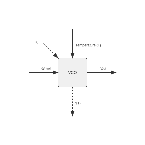
5.2 Performance Optimization Techniques
In the realm of Applied Voltage Controlled Oscillators (VCOs), performance optimization is crucial for enhancing the effectiveness and reliability of these devices in various applications. The design and functionality of a VCO hinge on several intrinsic parameters such as frequency stability, phase noise, power consumption, and linearity, all of which can be fine-tuned through various strategies. To gain a comprehensive understanding, we must first dissect the fundamental aspects that contribute to VCO performance, leading to a rational approach in employing optimization techniques.Understanding Key Parameters
Before diving into specific optimization techniques, let’s briefly summarize the vital parameters that dictate VCO performance:- Frequency Stability: This refers to how consistently the VCO can maintain its frequency over time and under varying temperature and power supply conditions.
- Phase Noise: This indicates the short-term frequency fluctuations, which can disrupt reliable communication in high-frequency applications.
- Power Consumption: VCOs often need to be energy efficient, especially in battery-powered devices.
- Linearity: A significant factor that influences the range of frequencies produced by the VCO with varying input voltages.
1. Frequency Stability Improvement
To enhance frequency stability, one of the primary techniques involves the implementation of temperature compensation methods. For instance, incorporating temperature-sensitive components, such as thermistors, into the circuit can counteract the frequency drift associated with temperature changes. Additionally, utilizing high-quality passive components with minimal temperature dependence, such as polycarbonate or C0G capacitors, can further mitigate stability issues. For deeper insight, consider a mathematical approach to modeling temperature-induced frequency shifts in a VCO:2. Phase Noise Reduction
Phase noise can dramatically affect the spectral purity of the VCO output. A common method to reduce phase noise is through the application of phase-locked loop (PLL) techniques. By employing a PLL, one can lock the VCO output to a reference frequency, thus providing feedback that inherently reduces phase noise. Another approach involves using low-noise amplification techniques that aim to minimize power supply noise, which directly affects the oscillator’s stability. A careful selection and layout of power supply filtering components can prove beneficial here.3. Power Consumption Optimization
In applications where power efficiency plays a crucial role, reducing power consumption should be a priority. A suitable technique includes using CMOS technology for VCO designs, as CMOS circuits typically consume less power compared to bipolar counterparts. Dynamic voltage scaling is another effective approach whereby the VCO’s operating voltage is adjusted according to performance requirements. By analyzing and adapting the voltage supply based on load conditions, overall power efficiency can be greatly improved. Mathematically, the power consumption can be expressed as:4. Linearity Enhancement
Enhancing the linearity of the VCO can lead to better frequency response characteristics, ensuring it responds predictably to voltage changes. One technique involves implementing negative feedback mechanisms within the oscillator circuit. Such a setup can help reduce non-linear behavior driven by component imperfections or distortion. Additionally, designing the tuning characteristic curve to maintain a linear relationship between the input voltage and output frequency is crucial. This may involve circuit simulations to iterate on the design before final implementation.Conclusion
Implementing these performance optimization techniques in applied voltage-controlled oscillators can significantly enhance their utility across varied applications, including telecommunications, signal processing, and many modern electronic systems. By understanding the core parameters that affect VCO performance and employing strategic improvements, engineers and researchers can achieve reliable and efficient oscillator designs tailored to meet the demands of contemporary technology. Overall, the interplay of stability, noise, power efficiency, and linearity allows for a rich landscape of exploration in VCO design, underscoring the importance of a methodical and informed approach to optimization.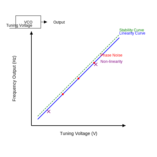
5.3 Measurement Techniques
Voltage Controlled Oscillators (VCOs) are critical components in numerous electronic applications such as communication systems, frequency demodulation, and synthesizers. To ensure optimal performance, precise measurement of the VCO's output signal characteristics is vital. This section delves into various measurement techniques used to evaluate different parameters of VCOs and discusses the inherent challenges and solutions associated with each method.
Understanding VCO Characteristics
Before measuring, it's essential to recognize the key parameters of a VCO that should be quantified:
- Frequency Stability: The ability of the oscillator to maintain a constant frequency under varying voltage conditions.
- Phase Noise: The short-term fluctuations in the phase of the signal, which can severely impact the performance of communication systems.
- Frequency Tuning Range: The extent of frequency variation the VCO can output as the control voltage changes.
- Output Power: The strength of the signal at the oscillator's output, often measured in dBm.
Measurement Techniques Overview
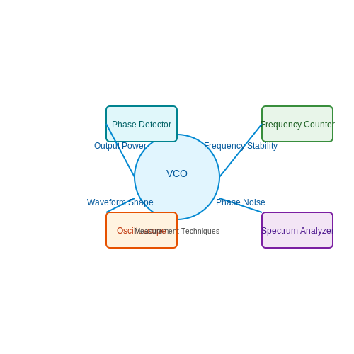
Several techniques can be employed to accurately measure the characteristics of VCOs. Each technique has specific equipment requirements and offers varying degrees of precision.
1. Frequency Counter
A frequency counter is one of the most straightforward tools to determine the frequency of a VCO output. It counts the number of cycles of the waveform over a specific time interval. The main advantages of using a frequency counter include:
- High Accuracy: Frequency counters can provide precise frequency readings up to 10 digits.
- Real-Time Measurement: Instantaneous feedback on frequency stability can be crucial in dynamic applications.
However, care must be taken to ensure that the counter's input range is compatible with the output voltage levels of the VCO.
2. Spectrum Analyzer
A spectrum analyzer provides comprehensive information regarding the frequency spectrum of the VCO output. It displays amplitude versus frequency, allowing for the analysis of phase noise and harmonic distortion:
- Phase Noise Measurement: By examining the noise floor around the fundamental frequency, engineers can assess the VCO's phase noise characteristics.
- Output Power Measurement: It assists in evaluating the power of the fundamental frequency along with any spurious emissions present.
Utilizing a spectrum analyzer requires knowledge of its settings, as incorrect frequency spans or resolution bandwidths can mislead results.
3. Oscilloscope
The oscilloscope is essential for observing the time-domain characteristics of the VCO output signal. In particular, it is crucial for:
- Waveform Shape Analysis: Ensuring that the output remains sinusoidal or exhibits the desired shape under various control voltages.
- Pulsed Signal Analysis: Used for time-sensitive applications, the oscilloscope can capture transient phenomena in the output signal.
Real-time analysis is a significant advantage, allowing for immediate adjustments and error corrections in a VCO design.
4. Phase Detector
A phase detector can be employed to measure the phase relationship between the VCO output and a reference signal. This technique is especially relevant in applications requiring tight phase control, such as in phase-locked loops (PLLs).
The phase error can be quantified, and this is crucial for characterizing the performance of the VCO in synchronization applications. A common method involves using a mixer to convert the frequency difference to a baseband signal, which can be easily analyzed for phase deviations.
Challenges and Considerations
Each measuring technique carries its own set of challenges, including:
- Signal Integrity: Noise from external sources can influence measurements, necessitating careful shielding and grounding.
- Equipment Calibration: Regular calibration of measurement tools is essential for ensuring accuracy.
- Environmental Factors: Temperature variations can affect a VCO’s frequency performance, necessitating controlled test environments.
Through employing a combination of these measurement techniques, engineers can obtain a comprehensive understanding of VCO performance in a practical setting, ensuring reliability and efficiency in electronic circuit design.
6. Academic Journals on Oscillator Design
6.1 Academic Journals on Oscillator Design
- Design and Analysis of a Low Power Voltage Controlled Oscillator — This IEEE paper presents a comprehensive study on the low power VCO architecture with a focus on minimizing power consumption without sacrificing performance characteristics such as frequency stability.
- A Theory of Oscillator Design — An ACM publication offering a foundational theory of oscillator design, focusing on signal generation's physics and mathematical models.
- Analysis and modeling of Colpitts oscillator design — This journal article details the modeling and analytical methods used in the design and optimization of Colpitts oscillators, including influence factors such as component selection on performance.
- Phase noise in voltage-controlled oscillators — Focuses on the analysis of phase noise in VCOs, discussing the mitigation techniques and their relevance to achieving high precision in mixed-signal circuits.
- Recent Advances in Oscillator Design — A ScienceDirect article summarizing the latest advancements in oscillator technologies, emphasizing the enhancement of frequency stability and tuning range.
- Quadrature oscillator design utilizing current-tunable circuit structures — Explores the design of quadrature oscillators using innovative, current-tunable circuit configurations aimed at improving their tuning bandwidth and linearity.
- A Low Voltage and Low Power VCO Design for Medical Ultrasound Imaging — Discusses a tailored VCO design for medical ultrasound applications, focusing on low voltage operations to ensure patient safety and device power efficiency.
- Wide-range CMOS voltage-controlled oscillator — This IOP publication introduces a CMOS-based VCO, friendly to integration with digital circuits, offering a broad tuning range critical for modern communication devices.
6.2 Textbooks on Electronics and Signal Processing
- Principles of Modern Wireless Communication Systems — A comprehensive guide covering fundamental and advanced concepts in wireless communication, this book offers detailed insights into VCOs used in wireless applications.
- Fundamentals of HVAC Direct Digital Control — Explore the roles of electronic control systems, including VCOs, within HVAC systems. This resource emphasizes the practical use of electronic signal processing in climate control technologies.
- Digital Signal Processing: A Practical Guide for Engineers and Scientists — This book provides engineers and scientists with a firm mathematical foundation and practical insights into signal processing, featuring real-world applications of VCOs in digital systems.
- Electronic Devices and Circuit Theory — Known for its comprehensive treatment of electronic circuits, including detailed sections on oscillators, this text explores both the theory and application of voltage-controlled oscillators.
- RF Microelectronics — Focusing on radio-frequency circuits, this book delves into the intricacies of VCOs within RF systems. It is a definitive source for understanding the integration of VCOs in microelectronic devices.
- Embedded Systems Design with the Texas Instruments MSP430 Series — This title covers the design of embedded systems and includes practical examples of using VCOs in microcontroller-based projects, making it invaluable for engineers looking to apply these concepts.
- Analysis and Design of Analog Integrated Circuits — A classic resource in electronics that offers extensive coverage on analog circuits, including comprehensive explanations and applications of VCOs in integrated circuit design.
6.3 Online Resources and Tutorials
- Design and Application of Voltage-Controlled Oscillators — This technical article by Texas Instruments delves into voltage-controlled oscillators (VCOs) design considerations, offering in-depth theoretical analysis and practical implementation techniques for engineers.
- Analog Devices Technical Articles — Featuring comprehensive articles that include tutorials on VCOs, signal processing, and electronic design, this resource serves advanced learners with cutting-edge insights into practical applications.
- VCO Tutorial - RF Wireless World — A detailed tutorial focusing on the types, specifications, and functioning of VCOs, specifically in RF applications. It provides insights into the design and optimization of VCO circuits for real-world applications.
- Voltage Controlled Oscillator Theory - Electronics Notes — This resource offers a breakdown of the theory behind VCOs, including various circuits configurations, their operating principles, and mathematical derivations to foster a deep understanding.
- An Introduction to Voltage Controlled Oscillators — A thorough introduction to VCOs, covering their role in modern electronics, typical circuit designs, and practical uses in different applications, complete with diagrams and equations for enhanced understanding.
- Understanding Voltage Controlled Oscillators - Digi-Key — This article provides insightful explanations on how VCOs operate, their key parameters, and considerations in circuit design, catering to both novice and experienced professionals in the field.
- Guide to Voltage Controlled Oscillators (VCOs) — A hands-on guide for constructing and experimenting with VCOs, designed to help engineers and hobbyists gain practical experience. It includes step-by-step instructions as well as circuit diagrams.
- Understanding Voltage-Controlled Oscillators - Maxim Integrated — This tutorial provides a comprehensive overview of voltage-controlled oscillators with emphasis on prominent product designs, characteristic features, and specific case study applications.