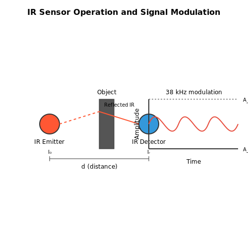
Applied Arduino Programming
1. Overview of Arduino Architecture
1.1 Overview of Arduino Architecture
The Arduino platform has revolutionized the approach towards embedded systems and physical computing due to its simplicity and flexibility. At its core, the architecture of an Arduino board comprises several fundamental components that facilitate the interaction between software and hardware. Understanding these components is crucial for advanced users who aim to leverage the full potential of Arduino in various applications, from prototyping to complex systems integration.
Microcontroller
At the heart of every Arduino board lies a microcontroller, which acts as the main processing unit. For example, the Arduino Uno employs the ATmega328P microcontroller. Understanding the architecture of this microcontroller can provide insights into optimizing programming for performance and functionality. The ATmega328P features:
- 8-bit architecture — It processes information in 8-bit blocks, influencing data handling and memory management.
- 32KB Flash memory — This is where your program is stored. Ensuring efficient code can maximize the use of this memory.
- 2KB SRAM and 1KB EEPROM — These provide runtime data storage and persistent memory, respectively.
These specifications significantly impact programming techniques, particularly regarding memory allocation and data retrieval strategies.
I/O Capabilities
The versatility of Arduino boards is also defined by their I/O capabilities, which can be categorized into three types: digital, analog, and PWM (Pulse Width Modulation). Each of these serves distinct purposes:
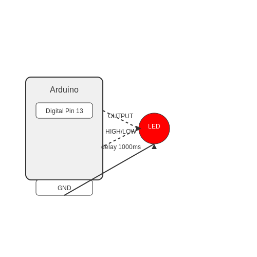
- Digital I/O pins — These pins can act as either input or output, utilized to control components like LEDs or read sensor states.
- Analog inputs — The Arduino can read varying voltage levels (0-5V), which is essential for interfacing with sensors that provide continuous output, such as potentiometers or temperature sensors.
- PWM outputs — These allow digital pins to simulate an analog output by varying the duty cycle of the signal, useful in applications like motor control.
Knowledge of these I/O capabilities enables advanced users to design complex systems that sensibly integrate multiple components.
Communication Interfaces
Arduino architectures are equipped with various communication interfaces, each conducive to specific applications. Most Arduino boards offer:
- Serial Communication — The RX and TX pins facilitate communication with serial devices, which is vital for logging data and debugging.
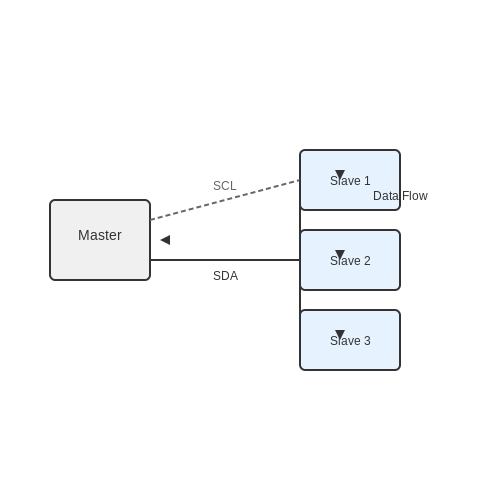
- I2C (Inter-Integrated Circuit) — This interface allows multiple devices to communicate using only two pins (SDA and SCL), which is efficient for sensor networks.
- SPI (Serial Peripheral Interface) — Utilized for high-speed communication with sensors or SD cards, SPI enables quick data transmission through a special bus architecture.
Understanding these interfaces informs choices about the types of sensors or modules to utilize within projects, enhancing the overall design.
Power Supply
Powering an Arduino board affects both its performance and longevity. There are multiple ways to supply power:
- USB Connection — This allows easy programming and generally provides sufficient power for low-demand applications.
- External Power Supply — This can be beneficial for powering external components that draw more current than what USB can reliably support. A barrel jack or header pins can be used for input.
It’s essential to understand the power requirements of connected peripherals to avoid under-voltage scenarios or damage to the board through excessive power supply.
Conclusion
The Arduino architecture presents a blend of simplicity and complexity that empowers advanced users to innovate and explore new realms of technical possibilities. By mastering the architecture of Arduino boards, users can create robust applications that push the boundaries of traditional embedded systems and physical computing.
1.2 Arduino IDE and Software Setup
Introduction to the Arduino IDE
The Arduino Integrated Development Environment (IDE) serves as the primary interface for programming Arduino microcontrollers. It provides a straightforward coding platform, which is essential for both novice users and advanced developers aiming to leverage the full potential of their Arduino hardware. The IDE supports C and C++ programming languages, which are highly portable and efficient for embedded systems. While the simplicity of the Arduino IDE is beneficial, its features such as libraries, one-click upload, and serial monitor add layers of versatility that advanced users can harness for complex projects.Installation of the Arduino IDE
To begin using the Arduino IDE, you must first install it on your computer. The installation process, although straightforward, requires specific steps: 1. Visit the official Arduino website to download the latest version of the IDE, available for various operating systems including Windows, macOS, and Linux. 2. Follow the installation instructions specific to your operating system. For Windows, this typically includes running an executable installer; macOS users often drag the Arduino application to their Applications folder. 3. After successful installation, launch the IDE. You will be greeted by a simple yet effective interface comprising features like the text editor, toolbar, and console area. Upon launching, familiarize yourself with various components: - The Text Editor: Where your code is written. - The Toolbar: Contains icons for compiling, uploading, and accessing the serial monitor. - The Console Area: Displays real-time feedback, errors, and debug messages.Configuration and Board Selection
Before you can program an Arduino, the IDE must be configured to communicate with your specific board. This involves selecting the right board and port via the Tools menu: 1. Navigate to Tools > Board and select your Arduino model (like Arduino Uno, Nano, or Mega). This selection enables the compiler to understand the architecture of the target board. 2. Next, set the correct Port under the Tools menu. This is where you connect your Arduino via USB; the port should appear due to the drivers installed automatically with the IDE.Installing Libraries
One of the most powerful features of the Arduino IDE is its extensive library support. Libraries extend the functionality of the IDE and allow developers to utilize existing code for complex tasks without writing them from scratch. To install libraries: 1. Go to Sketch > Include Library > Manage Libraries. 2. Use the Library Manager to browse or search for libraries relevant to your project, such as those for sensors, actuators, or communication protocols. 3. Click on "Install" next to the desired library, and once installed, it can be included in your projects with a simple `#include` directive.Writing and Uploading Code
After setting up the IDE and necessary libraries, you can begin writing your Arduino sketch. The structure of a basic Arduino program, or sketch, typically comprises two essential functions: 1. `setup()`: Configures the initial settings, runs once at startup. 2. `loop()`: Executes continuously after the setup function. A typical sketch can look as follows: cpp void setup() { Serial.begin(9600); // Initialize serial communication at 9600 bits per second } void loop() { Serial.println("Hello, Arduino!"); // Print message to the Serial Monitor delay(1000); // Wait for a second } To upload the code to the Arduino board, simply click the upload icon in the toolbar. The IDE will compile the code, and upon success, it will transfer it to the board.Utilizing the Serial Monitor
The Serial Monitor is an invaluable tool within the Arduino IDE, enabling real-time communication between your computer and Arduino. It can be utilized for debugging by printing variable values or debugging messages. Access it via Tools > Serial Monitor or by clicking on the magnifying glass icon in the top right. Ensure that the baud rate of the Serial Monitor matches that set in your sketch (like 9600 bps in the example).Conclusion
Setting up the Arduino IDE effectively allows advanced users to streamline their development process. With a clear understanding of board configuration, library management, and the function of the serial monitor, engineers and researchers can pave the way for innovative projects leveraging Arduino’s capabilities. By focusing on integrating real-world applications, transitioning seamlessly between features, and emphasizing best programming practices, one can utilize the Arduino IDE as a powerful tool for both research and experimentation in electronics and programming.1.3 Basic Programming Concepts
When working with Arduino programming, it is crucial to grasp the fundamental concepts that form the backbone of your projects. This section elucidates the basic programming concepts that are vital for harnessing the full potential of the Arduino platform.Data Types and Variables
At the core of any programming language are data types. In the Arduino programming environment, data types determine the kind of information that can be stored and manipulated. The most common data types used in Arduino are:- int: Used for integers, typically ranging from -32,768 to 32,767.
- float: Represents floating-point numbers, allowing decimal points.
- char: Represents a single character data (e.g., 'A', 'b', '3').
- String: A sequence of characters or text.
Control Structures
Control structures play a pivotal role in directing the flow of a program. They include conditionals and loops, which enable developers to build dynamic, responsive Arduino applications. Conditional Statements are used to perform different actions based on varying conditions. The most common are if-else statements: cpp if (temperature > 30) { // Code to turn on the fan } else { // Code to keep the fan off } Loops, on the other hand, allow for repeated execution of a block of code as long as a specified condition is true. Below is an example of a `for` loop used to control an LED: cpp for (int i = 0; i < 10; i++) { digitalWrite(LED_BUILTIN, HIGH); // Turn the LED on delay(1000); // Wait for a second digitalWrite(LED_BUILTIN, LOW); // Turn the LED off delay(1000); // Wait for a second } Loops can significantly enhance the flexibility and efficiency of your Arduino sketches, especially in scenarios requiring repetitive tasks, such as polling sensors or blinking LEDs.Functions
Functions are essential programmers' tools, allowing for the encapsulation of repeating code into reusable blocks. This promotes cleaner code organization and simplifies the debugging process. For instance, you might create a function to read sensor values: cpp int readTemperature() { // Code to read temperature sensor return temperatureValue; } By invoking `readTemperature()`, one can efficiently obtain the sensor's value whenever needed without re-writing the reading logic.Libraries
The Arduino ecosystem boasts a rich array of libraries that extend the functionality of sketches and simplify complex tasks. Libraries provide pre-written code that can handle various tasks, from interfacing with different sensors to controlling motors. For example, utilizing the DHT Sensor Library simplifies the task of reading temperature and humidity from a DHT11 sensor, enabling you to focus on other aspects of the project: cpp #include1.4 Input and Output Functions
Understanding Input and Output Functions in Arduino
In the realm of microcontroller programming, the manipulation of physical components is pivotal. Arduino, a cornerstone development platform, excels in its ability to interface with sensors and actuators through well-defined input and output (I/O) functions. This subsection delves into both the theory and practical applications of these functions, emphasizing their critical role in enabling interaction with the physical world.Input Functions
Input functions serve as the gateway for Arduino to receive data from external sources, such as sensors or user-interface devices. The analogRead() and digitalRead() functions are the primary mechanisms utilized for capturing input signals. The digitalRead(pin) function assesses whether a specified digital pin is receiving a signal. It returns a binary value - HIGH (1) for an active signal and LOW (0) for an inactive state. This is crucial for interfacing with simple components like switches or buttons where the state change can trigger actions in the program. On the other hand, analogRead(pin) is employed to capture varying voltages from an analog sensor, translating these levels into a range of values from 0 to 1023. This function uses the integrated analog-to-digital converter (ADC) of the Arduino, which typically utilizes a 10-bit resolution. The output can be modeled using the following equation for voltage determination:Practical Example of Input Functions
To illustrate the application of these functions, consider a rudimentary temperature sensing scenario. A thermistor connected to an analog pin can provide temperature readings that vary with resistance. By employing analogRead(), we can capture these fluctuations, which can then be processed for display or control actions, such as activating a fan based on the temperature threshold.Output Functions
Once input data is processed, the Arduino can interact with the external environment through output functions. The most prevalent functions are digitalWrite() and analogWrite(), facilitating control over connected actuators. The digitalWrite(pin, value) function outputs a binary signal to a specified pin, with “HIGH” or “LOW” dictating the state of the pin. This is fundamental for controlling digital devices like LEDs or relays. For example, turning an LED on or off involves setting the appropriate pin HIGH or LOW. In contrast, analogWrite(pin, value) outputs a value from 0 to 255 connected to the PWM (Pulse Width Modulation) enabled pins of the Arduino. This allows for the control of devices such as motors or LEDs. The effective voltage seen by the actuator can be derived from the PWM duty cycle:Real-World Application of Output Functions
Consider a simple automated lighting system that utilizes a light-dependent resistor (LDR) for input and controls an LED for output. When the ambient light falls below a certain level, the Arduino reads this state using analogRead() and subsequently triggers digitalWrite() to illuminate the LED. This case exemplifies the synergy between input and output functions in practical applications.Conclusion
The manipulation of input and output functions in Arduino programming forms the backbone of many embedded systems. By understanding and applying these functions, engineers and researchers can create more effective and responsive systems that seamlessly interact with the physical world, paving the way for innovative applications across various fields.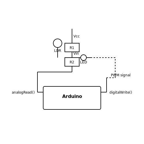
2. Understanding Sensors and Their Types
2.1 Understanding Sensors and Their Types
In the realm of applied Arduino programming, an essential component of successful projects is the understanding of sensors and their classifications. Sensors serve as the primary interfaces that allow systems to perceive their environment and gather data critical for processing tasks. This section delves into various sensor types, their principles of operation, applications, and integration with Arduino systems.
Types of Sensors
Sensors can be broadly categorized based on their principles of operation and the type of data they measure. Among the vast array, we mainly discuss:
- Analog Sensors: These sensors output continuous signal values corresponding to the physical quantity being measured. Examples include temperature sensors (like thermistors), potentiometers, and light-dependent resistors (LDRs).
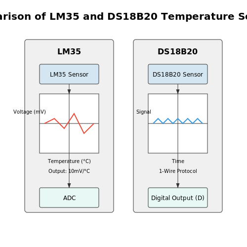
- Digital Sensors: In contrast, digital sensors provide discrete signal values, typically via binary representations (high or low). Common examples are digital temperature sensors like the DS18B20 and digital pressure sensors.
- Biosensors: These specialized sensors are employed for detecting biological elements and are increasingly relevant in health diagnostics. They use biochemical processes to measure variables such as glucose levels in diabetic patients.
- Proximity Sensors: These sensors detect the presence or absence of an object within a certain range without physical contact. Applications range from automatic doors to obstacle detection in robotics.
- Motion Sensors: These include accelerometers and gyroscopes that detect changes in motion or orientation and are pivotal in mobile devices and gaming controllers.
Analog vs. Digital Sensors
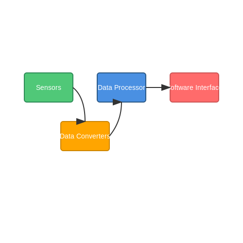
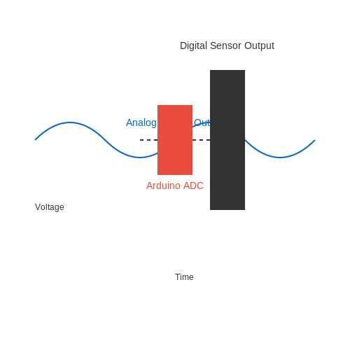
Understanding the difference between analog and digital sensors is crucial for selecting the appropriate type for your project. Analog sensors, as previously mentioned, output a variable voltage which can be interpreted by Arduino's analog input pins. The conversion of this signal is carried out through the Arduino's analog-to-digital converter (ADC) which quantizes the continuous signal into discrete levels.
The mathematical relationship governing this can be characterized by the formula:
where $$V_{out}$$ is the analog voltage output, $$V_{max}$$ is the maximum reference voltage supplied, $$N$$ is the number of bits in the ADC (commonly 10 bits in Arduino), and $$ADC_{value}$$ is the digital representation of the analog signal.
Sensor Selection: Key Considerations
When integrating sensors into your Arduino projects, several factors must be assessed to ensure optimal performance:
- Range: The sensor’s operating range should closely match the expected range of the parameter you are measuring.
- Precision and Accuracy: These characteristics define the sensor's performance in terms of measurement fidelity.
- Response Time: Some applications may require rapid reading, making the sensor's response time critical.
- Interface Type: Consider whether the sensor's output is analog or digital and ensure compatibility with the Arduino I/O pins.
Practical Applications
Understanding the various types of sensors plays a pivotal role in the development of sophisticated Arduino projects. For example, creating weather stations involves employing temperature, humidity, and atmospheric pressure sensors, while developing a home automation system might integrate motion and light sensors to automatically control lighting based on occupancy and ambient light levels.
The integration of sensors into Arduino systems not only enhances the capability of electronic projects but also drives innovation in fields such as robotics, healthcare, and smart technologies. The real-world relevance of effectively utilizing sensors in these applications cannot be overstated, as accurate data collection and processing form the cornerstone of intelligent systems.
In conclusion, the heterogeneous world of sensors provides an array of functionalities that can be harnessed through Arduino programming. By understanding sensor types, their characteristics, and appropriate applications, engineers and researchers can leverage these components to create impactful technological solutions.
2.2 Data Acquisition from Sensors
The integration of sensors with Arduino platforms enables a myriad of applications ranging from environmental monitoring to advanced robotics. With their ability to collect real-time data, sensors serve as critical components that transform physical phenomena into measurable signals suitable for processing. This section outlines the principles of data acquisition from various sensors, emphasizing both theoretical foundations and practical implementations.Understanding Sensor Types and Signals
To effectively acquire data, it’s essential to understand the types of sensors and the nature of signals they produce. Sensors can be categorized into two primary types:- Analog Sensors: These sensors output continuous signals that correspond directly to the physical quantity they measure. Examples include potentiometers, thermistors, and light-dependent resistors (LDRs).
- Digital Sensors: These sensors provide discrete values, often leveraging binary outputs to represent data. Common examples are temperature sensors (e.g., DS18B20) and digital accelerometers.
Data Acquisition Process
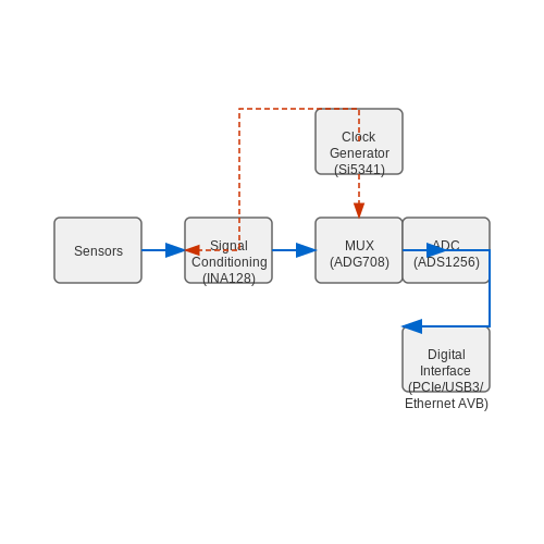
The data acquisition process involves several steps, including signal conditioning, sampling, and processing. Below, we will outline these steps:Signal Conditioning
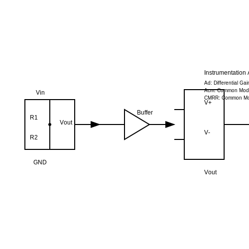
Before data can be obtained, signals from analog sensors often need conditioning. This may involve amplification, filtering, or linearization to improve measurement accuracy: 1. Amplification: Weak signals are enhanced using operational amplifiers (op-amps) to ensure that they fall within the range of the ADC. 2. Filtering: Low-pass filters can remove high-frequency noise, ensuring that only relevant signal components are processed. 3. Linearization: Some sensors, like thermistors, output nonlinear signals. Using mathematical models, these signals can be transformed into linear formats.Sampling
Once the signal is conditioned, the next critical step is sampling. According to the Nyquist theorem, to avoid aliasing, a signal must be sampled at least twice its highest frequency. This ensures that the continuous signal is accurately represented in digital form. The sampling frequency, denoted as \( f_s \), should be determined based on the application. Higher frequencies may be required for rapidly changing signals but come with increased processing demands.Processing
After sampling, the acquired data can be processed. In the context of Arduino, this usually involves programming the microcontroller to interpret the sensor data. Basic arithmetic operations, filtering algorithms, or even machine learning models can be applied depending on the application’s complexity.Practical Implementation with Arduino
Let’s explore a basic implementation involving an analog temperature sensor—the LM35. The following Arduino sketch demonstrates how to read the sensor's output, convert it to temperature in degrees Celsius, and display it on the Serial Monitor.
#define sensorPin A0

void setup() {
    Serial.begin(9600);
}

void loop() {
    int sensorValue = analogRead(sensorPin);
    float voltage = sensorValue * (5.0 / 1023.0);
    float temperatureC = voltage * 100; // LM35 outputs 10mV per degree Celsius

    Serial.print("Temperature: ");
    Serial.print(temperatureC);
    Serial.println(" °C");
    delay(1000);
}
Conclusion
Understanding the intricacies of data acquisition from sensors not only enables engineers and researchers to interact meaningfully with the physical world but also paves the way for innovations in fields ranging from automation to data analytics. The process of signal conditioning, sampling, and processing serves as a foundational pillar for building sophisticated systems capable of autonomous decision-making and real-time data handling. By mastering the details discussed in this section, one can leverage the full potential of Arduino-based sensor systems for a vast array of applications, ultimately contributing to advancements in technology and engineering.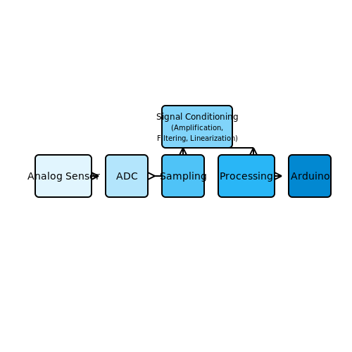
2.3 Popular Arduino Modules (e.g., Ultrasonic, Bluetooth)
Arduino's versatility is largely attributed to its wide array of modules that enhance its functionality and extend its capabilities into various domains, such as robotics, IoT, and automation systems. This section delves into some of the most popular modules used by advanced users, specifically focusing on ultrasonic sensors and Bluetooth modules, highlighting their operation, integration, and real-world applications.
Ultrasonic Sensors
Ultrasonic sensors are used extensively in distance measurement applications and are favored for their accuracy and versatility. They operate based on the principle of emitting ultrasonic waves at a frequency above the human hearing range, typically around 40 kHz. When these waves hit an object, they reflect back to the sensor, allowing it to measure the time taken for the waves to return. Using the speed of sound in air (approximately 343 meters per second), the distance can be calculated with high precision.
The distance D can be derived using the formula:
Where:
- D is the distance to the object.
- t is the time elapsed between sending and receiving the sound wave.
- v is the speed of sound in air (343 m/s at 20°C).
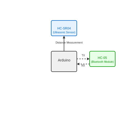
In terms of integration with Arduino, ultrasonic modules like the HC-SR04 are commonly used for distance measurement. They typically consist of two key components: a transmitter and a receiver. The transmitter emits the sound wave, and when it detects the reflected wave through the receiver, it computes the distance based on the time difference.
Applications
Ultrasonic sensors find applications in various fields:
- Robotics: For obstacle detection and avoidance.
- Automotive: Distance measuring systems for parking assistance.
- Industrial Automation: Level detection in tanks and silos.
Bluetooth Modules
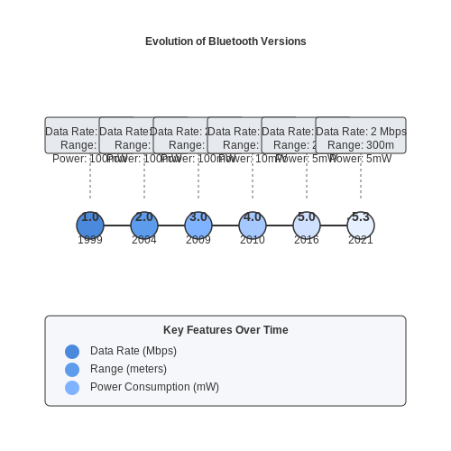
Bluetooth technology facilitates wireless communication between devices, enabling them to connect without physical cables. Arduino-compatible Bluetooth modules, such as the HC-05 and HC-06, make it easier to embed this technology into projects. These modules comply with Bluetooth 2.0 standards and can communicate within a range of approximately 10 to 100 meters, depending on the environment.
The HC-05 module offers two operational modes: master and slave. This dual capability allows for more complex networked applications. For instance, in a robotics project, an Arduino can act as a master device that communicates with multiple slave devices, such as mobile applications or other Arduinos, enabling sophisticated control commands.
Integration and Coding
Integrating a Bluetooth module with an Arduino is relatively straightforward. Typically, the RX and TX pins of the Bluetooth module connect to the TX and RX pins of the Arduino (cross-connected). This setup allows for serial communication using the Arduino’s Serial library. Below is a succinct example that establishes a basic serial communication setting:
#include <SoftwareSerial.h>

SoftwareSerial bluetooth(2, 3); // RX, TX

void setup() {
  Serial.begin(9600);
  bluetooth.begin(9600);
}

void loop() {
  if (bluetooth.available()) {
    Serial.write(bluetooth.read());
  }
  if (Serial.available()) {
    bluetooth.write(Serial.read());
  }
}
This code sets up a Bluetooth communication channel at 9600 baud, allowing data to flow bi-directionally between the Arduino and the Bluetooth device.
Real-World Applications
Bluetooth modules enable numerous real-world applications:
- Home Automation: Controlling devices using a smartphone.
- Wearable Devices: Collecting and transmitting health and fitness data.
- Robotics: Remote control of robots via mobile applications.
In essence, the combined use of ultrasonic sensors and Bluetooth modules exemplifies how Arduino modules empower users to create sophisticated and innovative projects that can monitor, control, and automate elements across various applications.
2.4 Interfacing Sensors with Arduino
Interfacing sensors with Arduino provides an indispensable method for gathering real-time data and implementing various applications in fields such as robotics, environmental monitoring, and automation systems. As you delve deeper into the realm of Arduino, you'll discover how effectively these microcontrollers can interact with an array of sensors—transforming raw data into meaningful insights.Understanding Sensors
Sensors are devices that convert physical phenomena—such as temperature, pressure, light, or motion—into electrical signals. When interfaced with Arduino, these signals can be translated into digital data that can be processed or displayed. Each sensor can be categorized based on its output signal type, specifically analog or digital. - Analog Sensors produce a continuous range of values. For instance, a potentiometer outputs a voltage corresponding to the position of its shaft, providing an infinite number of values within its operating range. - Digital Sensors produce discrete values, typically either high or low signals. A common example is a motion sensor that detects movement and outputs a binary signal. The choice of sensors often depends on the desired application and the type of data to be collected.Connecting and Configuring Sensors
To interface a sensor with an Arduino, a few essential steps are usually involved: 1. Wiring the Sensor: Each sensor has specific wiring configurations. For instance, an analog sensor typically connects to an analog input pin on the Arduino, while digital sensors connect to digital pins. 2. Power Supply Considerations: Ensuring that the sensor receives the correct voltage is crucial. Most Arduino boards operate at 5V or 3.3V. Verify the sensor specifications to avoid damage. 3. Arduino Libraries: Many sensors come with pre-written libraries that simplify the coding process. Utilizing these libraries can significantly reduce setup time and configuration challenges.Example: Interfacing an LM35 Temperature Sensor
The LM35 is a commonly used temperature sensor that outputs a voltage linearly proportional to the Celsius temperature. To measure temperature using the LM35 with an Arduino, follow these steps: 1. Hardware Setup: Connect the LM35 sensor as follows: - Vout pin to A0 (Analog pin) - Vcc pin to +5V on the Arduino - GND pin to Ground 2. Code Implementation: Below is an example code snippet that reads the temperature and prints it to the Serial Monitor.
#include

const int sensorPin = A0; // LM35 output pin
float voltage, temperature;

void setup() {
    Serial.begin(9600);
}

void loop() {
    voltage = analogRead(sensorPin) * (5.0 / 1023.0); // Convert ADC value to voltage
    temperature = voltage * 100; // Convert voltage to temperature in Celsius
    Serial.print("Temperature: ");
    Serial.print(temperature);
    Serial.println(" °C");
    delay(1000); // Wait for 1 second
}
Integration into Projects
The ability to interface sensors not only enriches the functionality of Arduino-based projects but also enhances their relevance in real-world applications. For example: - Weather Stations: By interfacing multiple sensors, you can create a comprehensive weather monitoring system that tracks temperature, humidity, and atmospheric pressure. - Automated Greenhouses: Sensors can be employed to monitor soil moisture, temperature, and humidity, providing critical data that can automate watering and climate control systems. - Wearable Technology: Sensors like accelerometers and heart rate monitors can be integrated into wearable devices for health monitoring applications. Through these practical implementations, one can appreciate the transformative potential of combining sensors with microcontroller platforms like Arduino, making it a valuable skill for engineers and researchers alike. As you continue exploring the vast capabilities of Arduino, consider experimenting with various types of sensors and integrating them into innovative projects that can address real-world challenges.
3. Designing an Arduino-Based Project
3.1 Designing an Arduino-Based Project
Understanding the Conceptual Framework
Creating an Arduino-based project begins with a well-defined conceptual framework. This framework serves as the cornerstone for the entire design process and encompasses not just the immediate goals of the project but also the broader implications and potential applications. An effective starting point is to identify a problem or a need within your domain of expertise that can be addressed using the capabilities of Arduino. Real-world examples can include environmental monitoring, real-time data acquisition systems, robotics, and embedded control systems for industrial applications. Articulating the specific objectives of your project will offer a clear direction for your design efforts.Components Selection and System Architecture
Once the objectives are clearly outlined, the next step is to select the appropriate components. The Arduino platform is versatile, supporting various sensors, actuators, and communication modules. Choosing the right components is crucial for meeting the functional requirements of your project. To understand system architecture, it's important to consider the following components:- Microcontroller: The heart of the system, responsible for processing input and controlling output.
- Sensors: Devices that gather data from the environment (temperature, humidity, motion, etc.).
- Actuators: Components that perform actions, such as motors or relays, based on the microcontroller's commands.
- Communication Interfaces: Protocols (like UART, I2C, SPI) used to facilitate interaction among components.
Prototyping and Iteration
With a solid design in place, prototyping becomes the next natural step. The Arduino platform allows for rapid development and iteration, making it ideal for testing your design assumptions. Utilizing breadboards and jumper wires can provide a flexible environment to experiment with your layout and connections. As you prototype, it is crucial to:- Validate the functionality of each component individually before integrating them into the system.
- Monitor the system behavior through debugging techniques, such as serial output, to track variables and program flow.
- Keep documentation of changes made during the testing process; this will assist in revising your design later.
Designing for Scalability and Maintenance
Finally, consider designing your project with scalability in mind. This involves thinking beyond the current iteration and allowing room for future enhancements. For example, if designing a sensor network for data collection, consider the potential to add more sensors without significant overhaul of your existing architecture. Moreover, ensure that the code is modular. This practice streamlines maintenance and updates and enhances readability. For instance, employing functions for repetitive tasks will reduce the complexity of the main program loop, improving performance. Remember, engineering is a disciplined yet creative endeavor, where the interplay of theoretical knowledge and practical experience culminates in innovative solutions. Each stage from ideation to prototyping and iterative refinement not only hones your technical skills but also expands your understanding of system dynamics and electrical interactions — critical for any advanced-level project. Overall, the journey of designing an Arduino-based project is not merely about assembling components or writing code; it reflects a deeper engagement with principles that govern electronics and programming. Embrace the iterative nature of this process, remain attentive to your objectives, and you will find success in bringing your ideas to fruition.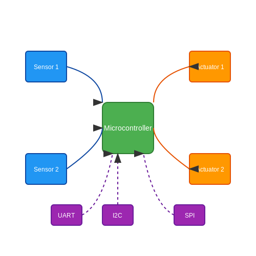
3.2 Prototype Building and Testing
In the realm of applied Arduino programming, prototype building and testing stand as crucial pillars that bridge the gap between conceptual ideas and functional devices. This section delves into the methodologies and best practices for assembling prototypes, ensuring rigorous tests, and refining designs for optimal performance.Understanding Prototyping
Prototyping is the process of creating a preliminary version of a device or system to evaluate its design and functionality. This iterative process allows engineers and researchers to identify design flaws, validate functionality, and assess user experience before moving to full production. A well-executed prototype can save significant time and resources, not only speeding up the development cycle but also enhancing the reliability of the final product. Rapid iteration and testing are essential components of successful prototyping.Identifying Objectives and Requirements
Before embarking on the physical assembly of a prototype, it is essential to clearly define the project objectives and technical requirements. This involves:- Defining the Problem Statement: Articulate the specific issue the prototype intends to address.
- Establishing Functional Requirements: Specify what the prototype must accomplish to be deemed successful.
- Setting Performance Criteria: Determine criteria such as speed, accuracy, and energy efficiency to guide design decisions.
Building the Prototype
The actual prototyping process can incorporate a variety of hardware components depending on the project requirements. Key stages of the prototype assembly include: 1. Component Selection: Choose appropriate sensors, actuators, and microcontrollers based on the defined requirements. For Arduino applications, components such as the Arduino Uno, Mega, or Nano may fit various scenarios. 2. Circuit Design: Create a schematic diagram that illustrates how the components will interconnect. This might involve the use of software tools such as Fritzing or KiCad for visual clarity. 3. Breadboarding: Utilizing a breadboard allows for a flexible setup where components can be easily connected and reconfigured without soldering. Breadboarding is highly beneficial during the testing phase, as it allows for rapid modifications. 4. Programming: Develop the necessary firmware for the Arduino. By leveraging the Arduino IDE, you can write and upload code that controls inputs and outputs effectively, handling everything from sensor readings to actuator responses.Testing the Prototype
Once the prototype is built, rigorous testing is crucial to ensuring both safety and functionality. This phase involves: - Unit Testing: Evaluate individual components to ensure they operate as intended. For example, test a temperature sensor by verifying that its output corresponds accurately to known temperature settings. - Integration Testing: Assess how well the combined system components work together. Employ simulation tools to observe interactions and ensure compatibility. - Performance Testing: Measure the prototype against the established performance criteria. Utilize tools such as oscilloscopes and multimeters to gather data on operational parameters. - User Testing: Depending on the application, gather feedback from potential users. This could involve using questionnaires or direct observation to ascertain usability and practical effectiveness. Throughout testing, it is essential to document findings meticulously. Note any discrepancies between the expected and actual performance, as this information will be invaluable for subsequent iterations.Iterative Refinement
Prototyping and testing are inherently iterative. Feedback gathered during testing should inform design adjustments. Modifications may involve changing component specifications, enhancing the software algorithms, or even altering the overall architecture of the project. Each cycle of refinement pushes the prototype closer to a polished final product. In conclusion, this focused approach to prototype building and testing not only enhances the likelihood of success in Arduino projects but also ensures that the resulting systems are robust, efficient, and user-friendly. By committing to a thorough, systematic process, engineers and researchers can bring their innovative ideas to fruition, effectively bridging theory and application in the exciting field of electronics.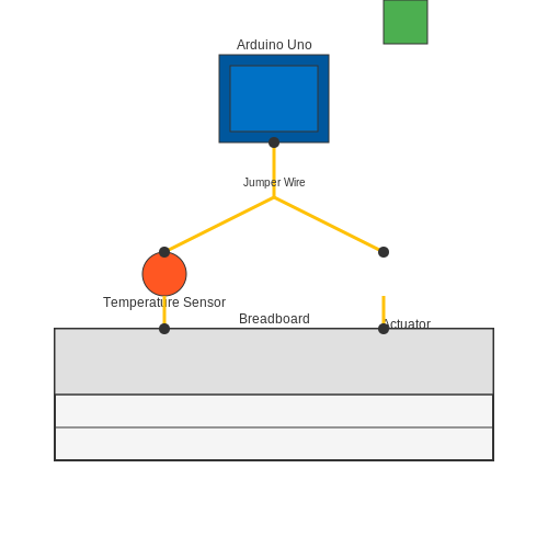
3.3 Common Challenges and Troubleshooting
When embarking on a journey of applied Arduino programming, engineers and researchers often encounter a range of technical challenges. Drawing from extensive real-world experience and scientific principles, this section aims to illuminate these common obstacles and present practical troubleshooting strategies that can enhance your project outcomes.Error Codes and Debugging Techniques
One of the first challenges faced when programming an Arduino is encountering error codes during compilation or upload. Each error code, while sometimes cryptic, offers valuable clues on what went wrong. For instance, a common compilation error is `exit status 1`, which typically indicates that the code cannot be compiled successfully due to syntax errors or incorrect library references. To tackle such issues effectively:- Read the error messages carefully: Often, the line number indicated in the error message points you directly to where the problem lies.
- Utilize the Serial Monitor: This built-in tool in the Arduino IDE can drastically improve debugging by providing real-time feedback during code execution.
- Incremental Testing: Break your code into smaller segments and test each part individually to isolate the problem.
Connection and Circuit Issues
Another prevalent challenge is establishing stable hardware connections. Many Arduino projects involve intricate circuits where even minor errors can lead to malfunctions. Problems often emerge from loose wires, incorrect pin connections, or power supply inconsistencies. To mitigate these issues, consider the following strategies:- Thorough Documentation: Keep a well-documented schematic or wiring diagram that indicates proper connections.
- Visual and Physical Checks: Regularly inspect breadboards and connections, as vibrations may lead to disconnections.
- Use of Multimeter: Measuring voltage and continuity can help verify circuit integrity prior to code execution.
Sensing and Actuation Challenges
Arduino applications often center around sensory input and actuative output, but discrepancies in sensor behavior can lead to unexpected results. Sensors like ultrasonic range finders or temperature sensors may produce erroneous reading due to environmental factors or incorrect scaling. Common strategies for this section include:- Calibration: Regularly calibrate sensors according to manufacturer specifications to ensure accuracy.
- Data Filtering: Implement software-based filtering algorithms such as moving averages to smooth out erroneous spikes in sensor data.
- Environmental Isolation: Shield sensors from external interference, such as electromagnetic fields or extreme temperatures.
Library and Compatibility Issues
As Arduino continues to evolve, new libraries and APIs emerge, which sometimes causes compatibility issues with older versions. Library conflicts can lead to unexpected behavior or prevent compilation altogether. Here are some effective practices to navigate these issues:- Version Control: Regularly update libraries to their latest versions, while also maintaining a history of previous versions to revert changes if necessary.
- Consult Documentation: Frequently refer to library documentation for compatibility notes and function updates.
- Community Forums: Utilize forums like the Arduino official forum or Stack Overflow to seek assistance and learn about past experiences from other developers.
Case Studies and Practical Relevance
Learning from documented case studies can provide insights into common pitfalls and innovative solutions. For example, projects involving automated irrigation systems often experience challenges with soil moisture sensors and pump control logic. By methodically troubleshooting sensor readings and ensuring robust code logic, such projects can be refined to optimal performance. As you navigate through your Arduino programming journey, let insight gleaned from these common challenges guide your problem-solving approach. The more familiarity you gain with these concepts, the more adept you'll become at creating effective, efficient Arduino applications.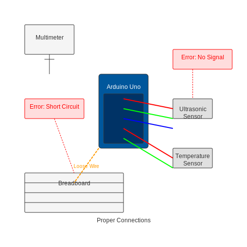
3.4 Finalizing and Presenting Your Project
In this subsection, we will delve into the essential steps required to finalize and present your Arduino project, emphasizing the importance of clarity, functionality, and effective communication of your ideas. Though much of the work lies in the initial design and development phases, how you present and document your project plays a critical role in its success, especially in professional environments.Understanding Your Audience
Before diving into the specifics of documentation and presentation, it is important to understand the audience for your project. Whether you are sharing your work with fellow engineers, presenting to stakeholders, or demonstrating to a general audience, the approach will differ significantly. Tailoring your presentation style, technical depth, and visual aids to meet the expectations and understanding levels of your audience is crucial.Finalizing the Project
The finalization stage involves several key aspects that ensure your project operates to specifications and is ready for demonstration: 1. Testing and Validation: Rigorous testing is essential. Create a test plan that outlines the parameters for evaluation. For example, if your project involves sensors, verify their accuracy and reliability. Perform stress testing to simulate operational conditions. 2. Optimization: Review your code and circuitry to identify any areas for optimization. This might include refactoring code for efficiency, reducing power consumption, or enhancing the robustness of your circuit design. Profiling tools in Arduino IDE can help measure execution times and optimize the most critical sections of your program. 3. Final Adjustments: Address any bugs or issues found during testing. Ensure all components are securely fastened, solder joints are intact, and that your connections reflect the schematic. This meticulousness can forestall potential problems during live demonstrations.Documentation
Having a comprehensive documentation strategy is as vital as the project itself. Useful documentation should encompass: - Project Overview: Summarize the project’s purpose, objectives, and functionalities. Include technical specifications and describe the hardware and software components utilized. - Schematic Diagrams: Create clear and detailed schematics using tools like Fritzing or Eagle. These diagrams provide the necessary blueprint for understanding the circuitry and component layout of your project. - Code Comments: Ensure clarity in your code with thorough comments. This is essential not only for others but also for future reference. Solutions to problems encountered should also be documented. - User Manual: Draft a step-by-step guide on how to operate your project. This will help users who are unfamiliar with the system understand its functionality and how to troubleshoot any issues that may arise.Preparing the Presentation
With a polished project and robust documentation, you're ready to prepare your presentation. This includes organizing your materials and planning the delivery of your ideas effectively: - Visual Aids: Use presentations, diagrams, and live demos to communicate effectively. Tools like PowerPoint or Google Slides can enhance your presentation. Make sure your visuals are clear and devoid of clutter. Graphical representations of data, flowcharts, and screenshots of your code can be highly effective. - Practice and Feedback: Rehearsing your presentation informs your efficiency and ensures you can articulate complex ideas succinctly. Use feedback from peers to refine your approach, focusing on areas that may require clarity or depth. - Engagement Techniques: Consider incorporating questions and answers in your presentation to interact with your audience. This not only creates engagement but also allows you to gauge understanding and interest.Real-World Applications and Case Studies
When presenting an Arduino project, it could be beneficial to anchor your work in the context of real-world applications. For example, a project that utilizes an Arduino for environmental monitoring can reference similar projects that have been successfully implemented in urban planning or disaster management. Highlighting practical implementation can enhance interest in your project and demonstrate its relevance. Ultimately, successfully finalizing and presenting your project showcases not just your technical prowess with Arduino, but also your capability to communicate complex information effectively—a valuable skill in any engineering or scientific discipline.4. Introduction to Libraries and Frameworks
4.1 Introduction to Libraries and Frameworks
The power and versatility of Arduino, a platform designed for both hobbyists and professionals, is significantly amplified by its extensive use of libraries and frameworks. Libraries, which encapsulate common functions, offer pre-written code that allows users to implement complex tasks without needing to code from scratch. Frameworks can be considered as larger structures that help organize and simplify the integration of multiple libraries, facilitating comprehensive development environments.
In an era where rapid prototyping and iterative development are crucial, employing libraries not only accelerates the design process but also enhances the reliability of the code. This approach enables engineers and researchers to focus on solving high-level problems rather than getting caught up in low-level implementation details.
Understanding Libraries
Arduino libraries are collections of pre-written code that simplify the interaction with hardware components, such as sensors or actuators. These libraries often include functions to control the components, easing the burden on the programmer. For instance, consider the widely used Wire library which facilitates I2C communication—this permits devices to communicate using only two wires, helping to reduce pin usage.
When incorporating a library, the typical process involves including the library in the sketch using the #include directive. Following this, the functions defined in the library can be utilized within the code. For example:
#include <Wire.h>

void setup() {
    Wire.begin(); // Initializes I2C communications
}

void loop() {
    // I2C communication code here
}
This snippet demonstrates how simple it can be to set up a library for use, illustrating the efficiency gained through these abstractions.
Frameworks in Arduino Programming
While libraries serve to encapsulate specific functionalities, frameworks take a more holistic approach to programming. They provide a structured way to build applications, integrating multiple libraries and offering a cohesive environment. An example within the Arduino ecosystem is the Arduino IDE itself, which serves as a basic framework encompassing project management, code organizations, and direct uploads to hardware.
Moreover, frameworks can introduce design patterns that promote better organization and reusability of code. For instance, utilizing the Model-View-Controller (MVC) pattern enables developers to separate business logic from user interface code, leading to cleaner, more maintainable projects.
This formula, representing Newton's second law of motion, is akin to the relationship between frameworks and libraries in Arduino programming. Just as the law maps out the relationship between force, mass, and acceleration, frameworks define the interaction between different libraries, guiding how they work together to form a cohesive application.
Practical Applications
In real-world applications, the utilization of libraries and frameworks can lead to significant advancements in technology development. For instance, robotics solutions benefit greatly from libraries that interface with motors and sensors, allowing for sophisticated autonomous functionality with minimal upfront coding effort. Similarly, in the domain of IoT (Internet of Things), leveraging frameworks enables streamlined development of interconnected systems that can communicate effectively over the Internet.
Furthermore, libraries often have extensive documentation and community support, which enhances troubleshooting and fosters innovation as users contribute to the ecosystem by developing and sharing new libraries and frameworks. The Arduino community exemplifies this collaborative spirit, providing forums, tutorials, and projects that inspire countless adaptations and creativity.
In summary, an advanced understanding of libraries and frameworks is essential for engineers and researchers aiming to leverage the full potential of Arduino for their projects. By building upon these abstractions, developers can create robust, efficient, and scalable solutions that push the boundaries of what's possible in embedded systems design.
4.2 Using Timers and Interrupts
In this section, we will delve into the sophisticated functionality of timers and interrupts within the Arduino programming environment. Understanding these two aspects is crucial for creating responsive and efficient applications, particularly in real-time systems. Timers enable precise time management, while interrupts allow the system to respond promptly to external events, enhancing the microcontroller's performance.
Understanding Timers
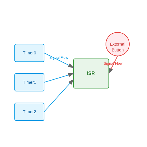
Timers are hardware components that count clock cycles in the microcontroller, providing developers with the ability to create time-based events in their applications. Arduino boards typically incorporate several timers, each with unique features and configurations. The most common timers in an Arduino are Timer0, Timer1, and Timer2, each of which serves distinct purposes depending on their internal architecture. The relevant timer registers (for instance, TCNTn, TCCRn, OCRn) govern the operation of these timers, facilitating tasks such as generating PWM signals, measuring time intervals, or creating delays.
To illustrate, consider a scenario where you need to generate a frequency modulated signal to control an actuator. By configuring one of Arduino's timers, you can set it to trigger an output pin at defined intervals. This approach is much more efficient than utilizing the delay() function, which halts the entire program and interrupts other processes.
Timer Configuration Example
The configuration of timers involves selecting the appropriate mode of operation, prescaler settings, and determining the desired frequency or duration. As a practical example, let’s configure Timer1 to generate a 1 Hz signal:
void setup() {
    // Set Timer1 to CTC Mode
    TCCR1A = 0;
    TCCR1B = 0;

    // Set the compare match register value for a 1 Hz signal
    OCR1A = 15624; // Assuming 16MHz clock, prescaler 1024

    // Configure Timer1 to clear on compare match
    TCCR1B |= (1 << WGM12);

    // Set prescaler to 1024
    TCCR1B |= (1 << CS12) | (1 << CS10);

    // Enable Timer1 interrupt
    TIMSK1 |= (1 << OCIE1A);
}

ISR(TIMER1_COMPA_vect) {
    // Toggle LED or perform desired action
}
Leveraging Interrupts
Interrupts provide a mechanism for the Arduino to pause its current execution context and temporarily switch to a separate function (an interrupt service routine, ISR) when a specific condition occurs. This is especially applicable in applications requiring immediate response, such as reading sensor data or processing input from buttons. Interrupts can be triggered by various events: external hardware signals or timer expirations.
Arduino supports two types of interrupts: external interrupts and timer interrupts. External interrupts are typically linked to pin changes, whereas timer interrupts are based on the timers' configured durations. Each interrupt type helps manage different use cases more effectively, allowing Arduino sketches to run asynchronously, thereby improving overall application efficiency.
Creating an Interrupt Example
To illustrate, let’s configure an external interrupt to respond to a button press:
void setup() {
    // Set pin for button
    pinMode(2, INPUT);

    // Attach interrupt to pin 2, triggered on rising edge
    attachInterrupt(digitalPinToInterrupt(2), handleButtonPress, RISING);
}

void handleButtonPress() {
    // Toggle an LED on pin 13
    digitalWrite(13, !digitalRead(13));
}
Applications of Timers and Interrupts
the capability to efficiently handle multiple tasks makes timers and interrupts invaluable in various applications. Whether managing a complex robotic system, gathering data from multiple sensors, or optimizing power consumption in battery-operated devices, these features enable implementations of precise timing and immediate responsiveness.
For engineers, physicists, and researchers, understanding and properly utilizing timers and interrupts can drastically improve the performance and reliability of their embedded systems. As you prepare to integrate these approaches into your own projects, consider how your specific application can benefit from non-blocking code execution and real-time event handling.
In conclusion, mastering timers and interrupts will elevate your Arduino programming skills and allow you to tackle more complex and responsive designs. Continue exploring the vast possibilities this knowledge unlocks, as it is a fundamental aspect of advanced electronic systems design, opening doors to innovative projects in various fields.
Debugging and Error Handling
Debugging and error handling are critical aspects of programming that ensure software reliability, efficiency, and maintainability, particularly in embedded systems like those built with Arduino. This section delves into the methodologies and tools that advanced programmers can employ to isolate flaws and rectify issues in their Arduino implementations.
Understanding Common Sources of Errors
Errors in Arduino programming can generally be categorized as syntax errors, runtime errors, and logical errors:
- Syntax Errors: These occur when the code deviates from the programming language's grammar rules. For instance, missing semicolons or braces can lead to compilation failures.
- Runtime Errors: These arise during the execution of the program, often due to trying to access invalid memory locations or divide by zero.
- Logical Errors: Such errors manifest when the program runs without crashing but produces unintended or incorrect results, often due to flawed logic within code structures.
Strategies for Effective Debugging
Advanced Arduino programmers can adopt several strategies to effectively debug their applications:
- Serial Debugging: Utilizing the Serial Monitor is one of the most effective ways to debug code. By inserting
Serial.begin(baudRate);in thesetup()function and usingSerial.print()orSerial.println()commands to output variable values and execution flow, developers can gain insights into how their program behaves at runtime. - Unit Testing: Implementing unit tests allows developers to isolate and test individual functions for correctness. Libraries such as ArduinoUnit help facilitate this practice, enabling a robust testing framework.
- Visual Debugging: For more complex systems, incorporating visual debugging tools such as graphical interfaces or simulation software can be beneficial. Tools like Fritzing can provide visual feedback on circuit designs, complementing the software development process.
- Using Breakpoints: Although not natively supported by the Arduino IDE, some advanced IDEs like PlatformIO allow the use of breakpoints for halting execution and inspecting variable states in real-time.
Error Handling Techniques
Beyond debugging, structured error handling is essential for robust application behavior, especially in industrial applications or systems requiring high availability:
- Try-Catch Mechanisms: While C++ (the language Arduino is based on) does not support exceptions as elegantly as some other languages, employing custom error handling through function return codes can assist in managing failures.
- State Machines: Utilizing state machines can help manage different states and transition conditions within your application. This technique not only organizes your code but also aids in gracefully handling errors by transitioning to a safe state instead of crashing.
Practical Application and Case Study
Consider a scenario where an Arduino-based weather station retrieves temperature and humidity data from sensors. If the temperature sensor fails, the system must handle this gracefully without crashing, perhaps by reattempting the read or falling back to a default value. By employing the strategies outlined above, the programmer can ensure that the application remains responsive and user-friendly even in unexpected situations.
By mastering debugging and error handling techniques, advanced Arduino programmers can significantly enhance the reliability and functionality of their projects, resulting in systems that can better handle real-world operational challenges.
4.4 Extending Functionality with Custom Functions
In the realm of embedded systems development, particularly when programming with Arduino, the use of custom functions can significantly enhance code readability, modularity, and reusability. As we delve deeper into applied Arduino programming, understanding how to create and implement custom functions becomes essential in addressing complex tasks efficiently.
At its core, a custom function can be thought of as a specific task packaged into a reusable block of code. Functions generally help to minimize redundancy by allowing engineers and programmers to define tasks that can be called upon multiple times throughout their programs, thereby ensuring a cleaner structure.
Defining Custom Functions
To define a custom function in Arduino's variation of C/C++, you start with the return type of the function, followed by the function name and parentheses which may contain parameters. A basic structure looks like this:
For example, consider creating a function to calculate the average of two numbers:
float calculateAverage(float num1, float num2) {
    return (num1 + num2) / 2;
}
This function, calculateAverage, takes in two float parameters, performs the arithmetic operation, and returns the average. Such an encapsulated function proves its utility when called multiple times with different values.
Benefits of Using Custom Functions
There are several compelling reasons for using custom functions in Arduino programming:
- Code Reusability: Say you've written a function for reading sensors. Instead of rewriting the entire sensor reading procedure each time you need it, you can simply call your function.
- Enhanced Organization: Structuring your program by categorizing functionality into functions can make the code easier to understand and navigate.
- Ease of Maintenance: If a function needs to be updated or debugged, you only have to change it in one location instead of multiple instances throughout the code.
Passing Parameters: By Value vs. By Reference
When dealing with parameters, it’s essential to understand the distinction between passing by value and passing by reference. Passing by value means that a copy of the variable is made, while passing by reference means that the referring variable itself is used. In Arduino programming, you can utilize references for larger data types to avoid the overhead of copying.
Here’s how a function might look when passing by reference:
void updateValue(int &value) {
    value += 10;  // The original value will be modified
}
In this example, invoking updateValue will increment the actual integer defined in the main program instead of a copy, showcasing another powerful method of extending functionality effectively.
Practical Applications
In real-world applications, custom functions find their utility across various domains, including robotics, automation, and IoT. For instance, a custom function could be responsible for managing data coming from multiple sensors, averaging values, or perhaps even overseeing communication protocols. By offloading repetitive tasks to functions, you can focus on higher-level logic and system architecture, increasing productivity and system reliability.
Case Study: Building a Temperature Monitoring System
Let’s consider a case study where the objective is to read temperature values from a sensor and trigger an alert based on predefined thresholds. By employing custom functions, the code for the temperature monitoring system can be modularized:
1. Read Sensor Value: Creating a function that handles the sensor communication. 2. Evaluate Temperature: A function that checks if the temperature crosses safe limits. 3. Trigger Alarm: Finally, a function dedicated to activating alarms or notifications.This modularity streamlines both the debugging process and future scaling of the system, allowing you to adjust individual components without disrupting the entire program.
In conclusion, mastering the skill of extending functionality through custom functions can significantly augment your Arduino programming, making your projects not only cleaner but also far more robust and adaptable for future developments.
5. Recommended Books
5.1 Recommended Books
- Programming Arduino: Getting Started With Sketches, Second Edition by Simon Monk — A comprehensive guide for those looking to develop foundational skills in Arduino programming. The book emphasizes step-by-step tutorials, useful for debugging and perfecting your Arduino-based projects.
- Arduino Cookbook, 3rd Edition by Michael Margolis — Providing hundreds of projects, this book is an essential resource for advanced users interested in delving deeper into sensor programming and interfacing with various hardware components.
- Beginning Arduino by Michael McRoberts — Offers a well-structured exploration of Arduino's core capabilities. Ideal for those with previous programming experience, it focuses on more complex programming constructs and offers projects that encourage creative applications.
- Mastering Arduino in 3 Hours by Dr. Peter Dalmaris — A time-efficient guide that presents core concepts in compact, knowledge-rich sessions. This is suitable for readers who want to optimize their learning time without skimping on essential advanced topics.
- Arduino Project Handbook Volume 1 and 2 by Mark Geddes — These volumes cover a variety of projects, offering a practical approach to mastering Arduino. Readers will appreciate the detailed breakouts and photograph diagrams for easier project completion.
- Arduino in Action by Martin Evans, Joshua Noble, and Jordan Hochenbaum — Focuses on real-world applications of Arduino, covering everything from basic to advanced projects. It's an excellent resource for those looking to integrate Arduino into professional engineering contexts.
- Practical Arduino Engineering by Harold Timmis — This book teaches advanced concepts by focusing on engineering applications, blending theory with practical circuit designs for sensor and automation projects.
5.2 Online Courses and Tutorials
As advanced learners in the realm of electronics and embedded systems, leveraging Arduino for complex projects requires not only foundational skills but also nuanced expertise that spans multiple domains. This section presents a curated selection of online courses and tutorials crafted for those who already have a robust understanding of electronics but seek to deepen their mastery of Arduino microcontroller programming.
Exploring Advanced Programming Concepts with Arduino
Many advanced-level courses offer an in-depth exploration of Arduino programming, focusing on sophisticated topics like data acquisition, signal processing, and real-time systems integration. These courses often incorporate mathematical modeling and algorithm optimization to enhance performance and reliability in real-world applications.
- Coursera - Internet of Things Specialization — A comprehensive series of courses providing insight into IoT development using Arduino, focusing on connectivity, sensor integration, and advanced data processing techniques.
- Udemy - Arduino Step by Step: Getting Serious — This course delves into more complex Arduino applications, including memory management, multitasking, and communication protocols, suitable for niche research and industrial applications.
- edX - UT AustinX Embedded Systems — Focused on embedded systems design and analysis, this program incorporates practical Arduino projects for real-world applications like autonomous systems and smart technologies.
Real-World Applications and Challenges
To truly comprehend the capabilities and potential of Arduino in professional settings, exploring case studies and engaging in project-based learning is imperative. Some courses emphasize problem-solving through the development of prototypes that address real-world challenges, such as environmental monitoring, automation, and system optimization.
- Pluralsight - Arduino Essentials — This course offers insights into integrating Arduino-based solutions within complex systems, enhancing the learner's ability to tackle challenges in automation and robotics.
- Adafruit - Learn Arduino — Offers project-based tutorials that advance from simple tasks to complex systems. Ideal for those looking to implement innovative Arduino projects in research or industry.
Mathematical Rigor and Computational Models
For the technically inclined, it is important to understand the mathematical principles and computational models that govern Arduino's operational framework. Some courses introduce numerical methods and algorithms that optimize task scheduling, resource management, and data handling processes on Arduino platforms.
- Nature - Arduino in Scientific Research — An article discussing the use of Arduino for scientific data acquisition, highlighting algorithmic challenges and solutions.
These resources provide advanced learners with the necessary tools to not only enhance their knowledge of Arduino but also apply it innovatively across various fields. The integration of theoretical knowledge with practical application empowers professionals to pioneer complex system designs using Arduino.
5.3 Community Forums and Support Groups
In the realm of Applied Arduino Programming, having access to community forums and support groups can significantly accelerate the learning process and help troubleshoot complex problems that arise during project developments. Community forums and support groups provide invaluable resources including discussions on advanced programming techniques, hardware integration tips, and real-world application challenges.
Importance of Community Engagement
For advanced users such as engineers, physicists, and researchers, engaging with online communities permits exposure to a wealth of practical knowledge. These forums often feature contributions from experts who provide insights into intricate details beyond typical documentation. This collective wisdom is especially valuable for addressing innovative projects where standard resources may fall short.
- Problem Solving: Community forums are exceptional for problem-solving. They often contain archives of past questions and solutions related to specific issues you might encounter.
- Knowledge Sharing: Participants freely share their custom libraries, optimization techniques, and novel applications that you can adapt for your own projects.
- Networking: Such platforms enable networking opportunities with professionals across the globe, potentially leading to collaborations or guidance from individuals with specific expertise.
- Staying Updated: The Arduino platform evolves, and communities are often the first to discuss updates, new hardware, and emerging trends.
Popular Arduino Community Forums
Below are a few of the key forums and support groups where you can connect with and learn from other advanced Arduino users.
- Arduino Forum: The official forum provided by Arduino, LLC, offers a platform for discussions spanning all aspects of Arduino projects. Featuring threads on everything from efficient circuit design to library development, it is a goto resource for in-depth technical advice.
- Stack Exchange - Arduino: As part of the Stack Exchange network, the Arduino forum specializes in question-and-answer style interactions. It is particularly useful for problem-specific inquiries due to its community-driven moderation and voting system.
- Reddit - Arduino: This popular subreddit is a hub for discussions, project showcases, and advice for both newcomers and seasoned Arduino developers. The platform’s informal structure allows for a diverse range of topics and rapid feedback.
Case Study: Optimizing Sensor Data Processing
A researcher working on an environmental monitoring system featuring Arduino-compatible sensors to gather and process real-time data can benefit from community insights. For instance, a forum thread detailing advanced filtering techniques could enhance signal clarity, or discussions about power management might improve the longevity of remote installations.
Sensor Data Filtering Example
Suppose your project involves processing analog data from multiple sensors to measure environmental parameters like temperature and humidity. Community discussions can offer tips on how to apply digital filters, such as a Kalman filter, to reduce noise and improve data reliability. The mathematical foundation for a simple Kalman filter would involve steps like defining the state variables, updating predictions, and then refining estimates based on sensor readings. Such conversations can provide both direction and sample code, helping streamline implementation.
For advanced applications and case-specific scenarios, engaging with communities will not only provide solutions but also stimulate innovations through peer reviews and suggestions.
5.4 Latest Research and Innovation in Arduino
As a platform that combines the accessibility of open-source hardware and software, Arduino has greatly impacted the fields of electronics and computing. This subsection delves into the latest research findings and innovative applications of Arduino technologies that have been buzzing the academic and industrial sectors in recent years.
Quantum Computing Interfaces
Recent research has explored the utilization of Arduino boards as interfaces in quantum computing experiments, particularly in the manipulation and measurement of qubits. The flexibility of Arduino platforms allows for customized solutions in controlling quantum systems, which is a significant leap from traditional laboratory setups.
A typical setup might involve Arduino as a middle-layer interface between classical computing shells and quantum materials. This integration provides low-cost, modifiable, and scalable solutions to complex control systems. Such hybrid systems enable broader access to quantum computing experiments, previously restricted to highly equipped labs.
Intelligent IoT Solutions
Internet of Things (IoT) deployments are leveraging Arduino's adaptability to create more intelligent and responsive systems. Recent innovation includes embedding Machine Learning models within Arduino to perform local data processing.
- Smart Agriculture: Arduino-based IoT solutions offer real-time monitoring of soil conditions, crop health indicators, and more, enabling precision farming.
- Home Automation: With integrated AI, Arduino can autonomously manage energy usage, security systems, and environmental controls, enhancing the efficiency of smart homes.
By embedding compact neural networks on Arduino devices, IoT systems can not only detect and respond to changes efficiently but can continue to function without constant cloud communication, enhancing security and reducing latency.
Biofeedback and Healthcare Monitoring
An exciting area of innovation is the use of Arduino in biofeedback and healthcare technology. Researchers are developing Arduino-based wearable devices that can track various physiological signals such as heart rate, temperature, and even biochemical markers, providing continuous health monitoring at a lower cost than traditional medical devices.
These devices often include sensors interfaced with Arduino boards that capture data, process it, and transmit it wirelessly to smartphones or cloud databases for further analysis. This capability allows real-time health assessments, crucial in managing chronic conditions or ensuring the patient's ongoing wellness.
Educational Robotics
Educational institutions are increasingly adopting Arduino for robotics education, driven by its ease of use and open-source nature. Recent educational tools built around Arduino provide interactive learning experiences ranging from simple robotic manipulators to complex autonomous vehicles.
With Arduino, students can easily connect various sensors and actuators to build robots that perform tasks or navigate environments, thus gaining hands-on experience with embedded systems and computer programming. This exposure is invaluable in nurturing the next generation of engineers and innovators.
Sustainable Energy Projects
In light of environmental challenges, Arduino platforms have been incorporated into sustainable energy research and applications. These include projects that monitor and optimize solar panel performance, manage wind turbines, and even experimental hydrogen fuel cell grids.
For example, Arduino can monitor real-time power generation and consumption in microgrid systems, allowing dynamic adjustments to enhance energy efficiency and reduce waste. Such systems are critical in maximizing renewable energy utilization and ensuring sustainable energy management.
In conclusion, Arduino continues to influence multiple research and industrial domains, offering tools that enhance capabilities through its flexible and open-source ethos. As technologies evolve, Arduino remains a key player, facilitating innovation and providing customizable solutions to complex problems.