Arduino Programming
1. What is Arduino?
1.1 What is Arduino?
Arduino is an open-source platform that encompasses both hardware and software, primarily designed for building interactive electronic projects. Created in 2005, Arduino has become a pivotal tool for engineers, researchers, and hobbyists alike due to its accessibility and versatility. The platform consists of a microcontroller, which is a compact integrated circuit designed to govern devices, and an Integrated Development Environment (IDE) that allows users to write and upload code to these microcontrollers.
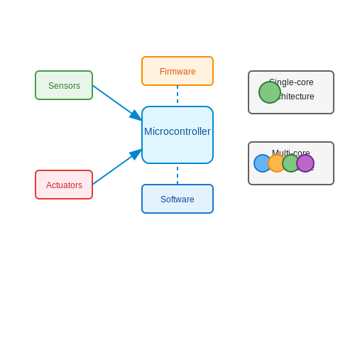
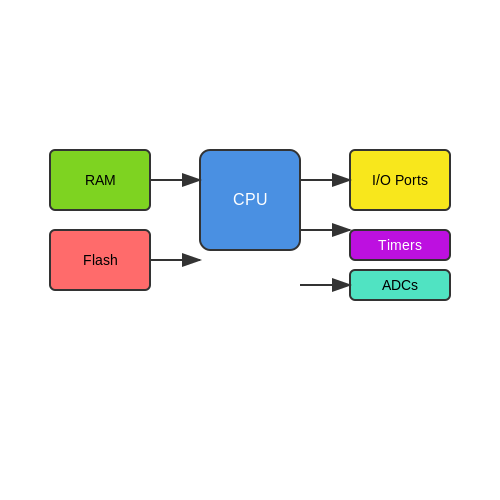
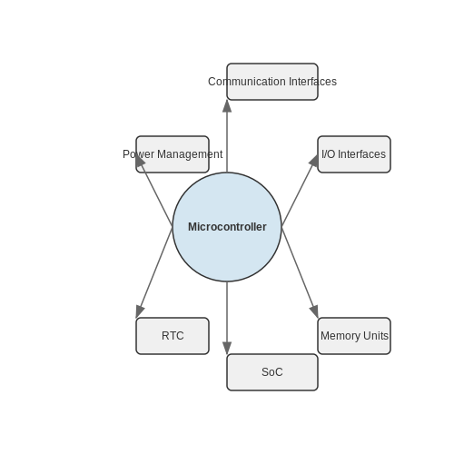
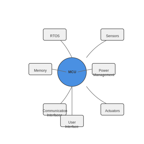
At its core, an Arduino board is built around a microcontroller (most commonly from the Atmel AVR line). This microcontroller serves as a brain, executing instructions dictated by user-written code while controlling various hardware components like sensors, motors, and actuators. Popular models of Arduino boards—such as the Arduino Uno, Mega, and Nano—offer different capabilities, such as varying input/output pins, memory capacity, and processing power, allowing users to select one that fits the specific needs of their projects.
One of the standout features of Arduino is its ease of use, which stems from its simplified programming language, based on Wiring. This C/C++ variant abstracts complex operations, making it approachable even for those who are not traditionally trained in programming. This aspect of Arduino has significantly lowered barriers to entry, enabling a diverse range of users to engage in physical computing.
Historical Context and Development
The inception of Arduino is rooted in the desire to create an inexpensive and easy-to-use tool for electronics education. The original project was developed at the Interaction Design Institute Ivrea in Italy. This educational focus influenced the platform's design, which emphasizes user-friendliness and a robust community support system, providing ample resources for learners. Over the years, the Arduino community has thrived, leading to countless libraries and software extensions, expanding the platform's functionality significantly.
Real-World Applications
Arduino has found applications across numerous domains, from robotics and automation to artistic installations and scientific experimentation. Some notable applications include:
- Robotics: Arduino serves as a control unit for robots, processing inputs from sensors and executing movements via motors.
- Environmental Monitoring: Sensors can be interfaced with Arduino to measure temperature, humidity, pollution levels, and other environmental factors, enabling data collection for research.
- IoT Projects: With the advent of Ethernet and Wi-Fi shields, Arduino can connect to the internet, facilitating Internet of Things (IoT) applications.
- Prototyping: Engineers and designers use Arduino to create rapid prototypes for testing and validating innovative ideas before final production.
The growth and adaptability of Arduino make it not only a powerful educational tool but also a pivotal resource in professional electronic design and development. Understanding its architecture and capabilities enables advanced users to significantly increase their proficiency in embedded systems design and implementation.
1.2 Setting Up the Arduino Environment
Establishing a robust environment for Arduino programming is critical for efficiently leveraging its extensive capabilities. In this section, we will explore the essential steps to set up your Arduino environment, providing you with a foundation to produce innovative projects and applications effectively.
1.2.1 Installing the Arduino IDE
The first step in setting up your Arduino programming environment is to install the Arduino Integrated Development Environment (IDE). The IDE provides a user-friendly interface where you can write code, compile it, and upload it to your Arduino board. You can download the IDE from the official Arduino website, which offers versions for various operating systems, including Windows, macOS, and Linux. After downloading, follow the installation prompts to set it up on your machine.
1.2.2 Configuring the Board and Serial Port
Once the IDE is installed, connect your Arduino board to your computer using a USB cable. Next, you will need to configure the IDE to recognize your board. In the Arduino IDE, navigate to Tools > Board and select your specific board model. This selection is pivotal as it affects the compilation process and ensures compatibility with the board’s architecture. Additionally, under Tools > Port, select the corresponding serial port to enable communication between the IDE and your Arduino.
1.2.3 Setting Up Libraries and Examples
To enhance your programming capabilities, the Arduino IDE supports numerous libraries that extend the functionality of your projects. Libraries are collections of pre-written code that simplify tasks such as sensor interface, communication protocols, and hardware control. You can manage libraries via the Library Manager found under Sketch > Include Libraries > Manage Libraries. Searching for and installing libraries relevant to your project needs will save considerable coding time.
1.2.4 Writing and Uploading Your First Sketch
After configuration, it is time to write a simple Arduino sketch, which is the Arduino term for a program. Consider the classic 'Blink' example, which makes an LED on the board blink on and off. Type the following code in the IDE:
void setup() {
    pinMode(LED_BUILTIN, OUTPUT);
}

void loop() {
    digitalWrite(LED_BUILTIN, HIGH); // Turn the LED on
    delay(1000);                     // Wait for a second
    digitalWrite(LED_BUILTIN, LOW);  // Turn the LED off
    delay(1000);                     // Wait for a second
}
To upload the sketch to the Arduino board, click the Upload button in the IDE. This process compiles your code and transfers it to the board, where it will run indefinitely. Understanding how to manipulate this environment will significantly enhance your projects, enabling real-time testing and debugging capabilities.
1.2.5 Troubleshooting Common Issues
While setting up your environment, you might encounter common issues such as board recognition failures or compile errors. Ensuring that the correct board and serial port are selected is paramount. Additionally, recompiling after making changes to the code can resolve many issues. Utilize the built-in serial monitor (`Tools > Serial Monitor`) within the IDE to debug communication and visualize outputs from your board.
In conclusion, the proper setup of your Arduino programming environment lays the groundwork for successful project execution. The ease of adjusting parameters, integrating libraries, and real-time monitoring provides a comprehensive platform for your advanced projects and experiments.
1.3 Installing Arduino IDE
Overview of Arduino IDE
The Arduino Integrated Development Environment (IDE) serves as a vital platform for developing projects leveraging Arduino microcontrollers. Well-regarded for its user-friendly interface, the IDE offers a variety of features such as syntax highlighting, a straightforward code editor, and easy access to libraries of existing code. Understanding the steps required to install the Arduino IDE is crucial for advanced users, as it will ensure a streamlined workflow for programming various Arduino-compatible devices. In this section, we will outline the steps for installation across different operating systems and introduce some of the advanced features the IDE offers.
System Requirements
Before proceeding with the installation, ensure that your system meets the minimum requirements to run the Arduino IDE effectively:
- Operating Systems: Windows 7 or later, macOS 10.10 or later, or a Linux distribution supporting 64-bit.
- RAM: At least 1 GB is recommended for optimal performance.
- Storage: A minimum of 200 MB of free disk space.
- Processor: Modern multi-core CPU recommended.
Installation Steps
Depending on your OS, the installation steps vary:
Windows Installation
For Windows users, follow these steps:
- Visit the Arduino Software Download Page to download the installer package.
- Run the downloaded .exe file. You may be prompted to allow changes; accept this to continue with the installation.
- Follow on-screen instructions. Select your desired installation directory and complete the installation process.
macOS Installation
For macOS, installation is straightforward:
- Download the .dmg file from the official site.
- Open the downloaded file and drag the Arduino IDE icon to your Applications folder.
- Launch the Arduino IDE from your Applications directory.
Linux Installation
Linux users may experience some variations in installation based on distribution. The general approach is as follows:
- Navigate to the Arduino Software Download Page to find the appropriate package.
- Extract the downloaded tarball. For instance, you can use the terminal command:
tar -xvf arduino-*.*.tar.xz. - Navigate to the extracted folder and run the installation script using
sudo ./install.sh.
Configuring the Arduino IDE
Once the IDE is installed, it requires some initial configuration:
- Connect your Arduino board to the computer via USB.
- Select the board type from Tools > Board. Here, you can select from various Arduino models such as Arduino Uno, Mega, and Nano.
- Next, select the appropriate port under Tools > Port.
Advanced Features of Arduino IDE
The Arduino IDE is rich with features that facilitate a robust programming experience. Some notable advanced features include:
- C++ Library Support: Incorporate third-party libraries to enhance functionality.
- Serial Monitor: Utilize the Serial Monitor for real-time data communication and debugging.
- Board Manager and Library Manager: Efficiently manage installed boards and libraries through the dedicated interfaces.
By completing the installation and configuration of the Arduino IDE, you set the stage for advanced programming and seamless project execution. Utilize this tool not only for learning but also for pressing innovations in electronics and microcontrollers, impacting sectors like IoT, robotics, and automated systems.
10. Recommended Books on Arduino
10.1 Recommended Books on Arduino
- Getting Started with Arduino — Written by Arduino co-founder Massimo Banzi, this book provides a solid introduction to Arduino programming and electronics, explaining key concepts such as inputs, outputs, and sensors. Ideal for those who wish to build a strong foundational understanding before diving into more advanced projects.
- Beginning Arduino — This resource is targeted towards those who have a basic understanding of programming and electronics. It presents various hands-on projects with complete code examples and troubleshooting tips, enhancing both practical skills and theoretical knowledge in Arduino design.
- Arduino: A Quick-Start Guide — A pragmatic guide for engineers and researchers, this book delves into the nuances of Arduino programming, including coverage of memoization techniques and real-world application examples, making it a valuable reference for advanced-level readers.
- Advanced Arduino Programming: Mastering the Arduino Language — Authored by Simon Monk, this text explores deeper aspects of the Arduino environment, including memory management, project optimization, and interfacing with advanced hardware, thus offering insights into more efficient coding practices.
- Arduino Cookbook — For advanced users seeking practical knowledge, this book provides over 200 recipes for solutions to everyday problems, integration of modules, and deployment strategies. Each recipe is designed to address real-world challenges and frequently encountered issues.
- Programming Arduino: Getting Started with Sketches — This text not only covers the basics but expands into more complex programming tactics, catering to advanced users with in-depth explanations of digital and analog sensors, networking, and communication with other devices.
- Arduino Projects to Save the World — This book aligns closely with real-world applications, detailing projects that focus on sustainability and humanitarian uses of Arduino. It provides both inspiration and technical procurement for researchers interested in socially impactful Arduino application.
- The Art of Arduino — Focused on artistic and aesthetic uses, this advanced guide explores Arduino applications in creative technology fields. It is ideal for physicists and engineers seeking to blend electronic design with innovative art.
10.2 Useful Online Resources and Communities
When diving deeper into Arduino programming, harnessing online resources and engaging with vibrant communities can exponentially enhance your learning experience. These platforms offer valuable examples, problem-solving strategies, and collaborative environments that foster innovation. Below are some invaluable resources designed specifically for advanced users like engineers, physicists, researchers, and graduate students.- Arduino Language Reference — Provides comprehensive documentation on Arduino's programming language, detailing functions, variables, and libraries crucial for advanced projects, enabling users to write more efficient and powerful code.
- Arduino Forum — A robust online community where developers discuss a wide array of topics related to Arduino programming, hardware integration, and troubleshooting, making it an essential platform for real-time advice.
- Arduino GitHub Repository — Hosts Arduino's open-source software, including the IDE and libraries. Ideal for studying code examples, contributing to development, or staying updated with the latest changes in Arduino software.
- Instructables - Arduino — Contains user-generated tutorials and projects that integrate Arduino into complex systems, providing inspiration and insights into practical, real-world applications across various disciplines.
- Arduino YouTube Channel — Features tutorials, webinars, and presentations that cover both basic and advanced topics, allowing visual and auditory learners to reinforce their understanding of key concepts through multimedia.
- Reddit: Arduino — A forum for Arduino enthusiasts sharing project ideas, programming tips, and hardware hacks. It's a dynamic space for Q&A and discussions with a broad spectrum of users, from beginners to experts.
- Arduino on Stack Exchange — A question-and-answer platform where engineers and developers address specific technical issues related to Arduino. It's an invaluable source of expert advice and problem-solving strategies.
10.3 Documentation and Official Websites
Navigating the expansive landscape of Arduino programming requires a strong understanding of resources available for documentation and official guidance. These resources not only enhance your programming capabilities but also keep you abreast of community trends and innovative practices within the Arduino ecosystem. By engaging with official websites and documentation, advanced users can optimize their projects, troubleshoot issues effectively, and even contribute to community-driven projects.Official Arduino Documentation
Why Documentation is Important Documentation serves as the blueprint for comprehending complex systems within Arduino's expansive infrastructure. It provides detailed insights into hardware specifications, software libraries, and even intricacies of embedded systems programming. By leveraging quality documentation, experts can ensure their implementations are accurate, efficient, and innovative. Arduino offers official documentation through its main website, which includes thorough descriptions of functions, classes, and libraries. This facilitates the development of robust applications and empowers experts to experiment with unprecedented concepts.Using the Arduino Website
Main Features of the Official Site Visiting the Arduino Official Website provides a portal into numerous official resources:- Arduino Guides — An assortment of general guides for setting up and using various Arduino boards. It is essential for beginners to get started and for advanced users exploring new board capabilities.
- Arduino Tutorials — A collection of tutorials ranging from basic projects to complex applications. This is crucial for learning new programming techniques and understanding physical computing concepts.
- Arduino Language Reference — Detailed descriptions of the Arduino programming language including statements, functions, and libraries. This section is a key reference for coding precision and innovation.
- Arduino Pro — A segment dedicated to professional applications and advanced product designs for industrial, automation, and intricate IoT solutions.
- Arduino Blog — Regular updates and insights from developers and community projects. It is a resourceful platform to understand trends, innovations, and practical implementations from other experts.
Community Contributions and Support
The Role of the Community in Arduino Development The Arduino environment thrives not only on official documentation but also on robust community support that functions as a collective brain trust. Engaging with communities such as Arduino forums, GitHub repositories, and other collaborative platforms can serve as invaluable resources, particularly when working on unique or complex projects. Participation in the Arduino community makes it possible to exchange ideas, seek assistance, and provide support, paving the way for collective problem-solving and innovative breakthroughs. Access community libraries, projects, and enhancements through these platforms:- Arduino Forum — A platform offering peer support for coding, troubleshooting, and hardware projects. Engage in discussions, seek project feedback, and stay updated with community developments.
- Arduino GitHub — Explore official repositories, contribute to ongoing projects, and access an open-source ecosystem that supports shared development efforts.
- Arduino on Reddit — A community-driven space for open discussions, sharing innovative ideas, and receiving peer feedback. It's a dynamic environment for gathering practical insights.
2. Understanding the Arduino Language
2.1 Understanding the Arduino Language
The Arduino platform, which aims to simplify creating electronic projects, utilizes an integrated development environment (IDE) paired with a simplified programming language based on C/C++. This subsection will delve into the foundational aspects of the Arduino language, covering variable types, control structures, functions, and the event-driven nature of Arduino programming. By understanding these elements, readers will be better positioned to harness the power of Arduino for sophisticated applications such as robotics, IoT devices, and data acquisition systems.Arduino Language Overview
The Arduino language is designed to abstract much of the complexity commonly associated with microcontroller programming, thereby enabling engineers and researchers to focus on their specific application rather than underlying hardware intricacies. It is largely built upon C/C++, meaning anyone with a background in these programming languages will find familiar concepts throughout the Arduino codebase. Despite this simplicity, it retains the core structure, allowing for powerful functionality.Variable Types and Data Structures
At the foundation of programming in any language lies the concept of data types. In Arduino, several primitive data types are distinguished:- int: A basic integer type that can store values from -32,768 to 32,767.
- float: A data type used for floating-point numbers for precise calculations (up to 7 digits of precision).
- char: Allows the storage of single characters, ranging from -128 to 127, or 0 to 255 if unsigned.
- boolean: A binary type that can hold either true or false.
- String: A complex type that represents a sequence of characters.
Control Structures
Control structures in Arduino programming allow for decision-making and data processing. Key constructs include:- if-else statements: These are used for conditional checks that lead to different paths of execution based on boolean expressions.
- for loops: Iterative statements that execute a block of code a specific number of times. The syntax for a for loop is typically structured as follows:
$$ \text{for (initialization; condition; increment)}$$
- while loops: These loops continue execution as long as a specified condition remains true.
Functions and Libraries
Functions in Arduino programming encapsulate code for reuse and modularity. This aspect is vital for maintaining organized, efficient code. Developing custom functions allows programmers to break down large tasks into manageable segments. Arduino's extensive collection of libraries expands its capabilities significantly. Libraries consist of pre-written code that simplify complex tasks such as interfacing with various sensors or modules. For instance, utilizing the Servo library entails including the library and then invoking its functions to control a servo motor, as shown below:#include <Servo.h>
Servo myServo;
void setup() {
myServo.attach(9);
}
void loop() {
myServo.write(90); // Set servo to 90 degrees
delay(1000);
}Event-Driven Programming
One of the distinctive features of Arduino is its event-driven programming model, allowing actions to trigger in response to specific sensor readings or interrupts. The core loop, referred to as `loop()`, runs continuously after the `setup()` function is executed and can respond to real-time inputs. This paradigm is particularly useful in applications such as home automation or robotics, where sensors detect environmental changes, initiating timely reactions. As engineers or researchers delve further into the Arduino language, they will discover a multitude of applications by combining these fundamental elements. From automated sensor networks to human-computer interaction projects, understanding the Arduino language opens a gateway to innovative solutions. In summary, mastering the Arduino programming language requires familiarity with its basic data types, control structures, functions, and event-driven programming model. With this foundation, one can explore and create advanced applications tailored to specific needs in various fields, including robotics, environmental monitoring, and automation. By synthesizing this knowledge with practical applications, the Arduino language serves not just as a tool but as a bridge connecting the theoretical aspects of electronics with the limitless possibilities of real-world experimentation.2.2 Writing Your First Program
In the world of Arduino programming, the moment you begin to write your first program is both exhilarating and critical. This part of the tutorial will guide you through the process of creating a simple yet effective program that will illuminate the foundational concepts in Arduino programming while ensuring you grasp the underlying principles that govern how microcontrollers operate.Understanding the Basics of an Arduino Program
An Arduino program consists of several components that dictate how the microcontroller interacts with connected hardware. At its core, an Arduino program follows a structured format known as a sketch. This sketch typically includes two primary functions: `setup()` and `loop()`. The `setup()` function runs once when the program starts, serving to initialize settings, establish input/output parameters, and set the state of any other configurations. In contrast, the `loop()` function continuously executes after `setup()`, allowing your program to respond dynamically to inputs from sensors or user actions.Creating Your First Program
Let's construct a fundamental program that interacts with an LED. This example serves two purposes: it illustrates how program structure works and demonstrates the practical application of controlling output devices. The goal of this program is to turn an LED on for a second, then turn it off for a second, creating a blinking effect. 1. Setting Up the Environment: Ensure you have the Arduino IDE installed on your computer. Open the IDE and create a new sketch. 2. Writing the Code: Below is the code block for the blinking LED program.
// Define the pin number for the LED
const int ledPin = 13;

// The setup function runs once when the program starts
void setup() {
    pinMode(ledPin, OUTPUT); // Initialize the digital pin as an output
}

// The loop function runs repeatedly
void loop() {
    digitalWrite(ledPin, HIGH); // Turn the LED on
    delay(1000);                // Wait for a second
    digitalWrite(ledPin, LOW);  // Turn the LED off
    delay(1000);                // Wait for a second
}
Explanation of the Code
- Pin Definition: The code begins by defining the variable `ledPin` as the digital pin number to which your LED is connected. Pin 13 is commonly used due to its onboard LED connection on most Arduino boards. - Setup Function: Inside the `setup()` function, `pinMode(ledPin, OUTPUT);` sets the specified pin as an output. This is essential so that the Arduino knows it will send out voltage to control the LED. - Loop Function: In the `loop()` function, `digitalWrite(ledPin, HIGH);` instructs the Arduino to send voltage to the LED, turning it on. After a pause defined by `delay(1000);`, which represents 1000 milliseconds or one second, `digitalWrite(ledPin, LOW);` turns the LED off, followed by another delay of one second. This creates the blinking effect.Compiling and Uploading the Program
Once you’ve entered your program into the IDE, it’s crucial to compile it to check for errors. Click on the checkmark icon in the top left corner of the IDE. If no errors are present, connect your Arduino board to the computer via USB, select the correct board and port from the "Tools" menu, and click the right arrow icon to upload the code. This fundamental exploration of an Arduino program not only elucidates how to control hardware but also sets the foundation for tackling more complex projects. As you continue to innovate and experiment, the structure and mechanics learned in this simple LED example will apply broadly across your advanced endeavors in Arduino programming and embedded systems.Real-world Applications
Understanding how to write basic Arduino programs is instrumental for various applications ranging from simple LED control to sophisticated robotics and automated systems. As an engineer or researcher, mastering these concepts will allow you to prototype faster and implement intelligent systems efficiently. Whether you're working on automating home appliances, building interactive exhibits, or conducting scientific research, the ability to seamlessly handle microcontroller programming is invaluable in today's tech-driven era. With this foundation, you are now well-equipped to explore further programming techniques and integrate complex modules into your builds, such as sensors and motors, propelling you closer to realizing your innovative ideas.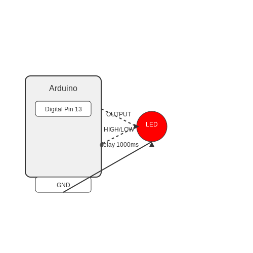
2.3 Uploading Code to Arduino
Having established a strong understanding of the Arduino platform and its programming environment, we now turn our focus to the critical process of uploading code to Arduino boards. This step is not merely a technical necessity; it plays a vital role in translating our written instructions into tangible, real-world functions through hardware integration. The efficiency of this process will significantly impact the performance and responsiveness of any project you undertake.
Understanding the Upload Process
To effectively upload code to an Arduino, one must first comprehend the underlying mechanisms driving the process. The Arduino Integrated Development Environment (IDE) offers a user-friendly interface for this task, converting human-readable code into binary format suitable for microcontrollers. During the upload process, several key steps occur:
- Compilation: The IDE compiles the written code (sketch) into machine language, which is a binary format that the microcontroller can understand.
- Connection Establishment: A serial connection is established between the computer and the Arduino board, typically via a USB cable, which acts as both a power source and data link.
- Flashing: The compiled binary is then transferred to the microcontroller’s flash memory, often referred to as 'flashing' the firmware.
- Execution: Once the upload is successful, the microcontroller begins execution, running the program according to the instructions encoded in the binary data.
Connection Protocols and Serial Communication
Typically, the USB connection utilizes a Universal Serial Bus (USB) protocol that wraps data within packets for reliable transmission. To ensure seamless communication, you need to select the correct serial port that corresponds to your board in the Arduino IDE. This can be done by navigating to Tools → Port and selecting the appropriate option. Understanding this process is fundamental, as mismatched settings can lead to upload errors, stalling your project's progress.
Common Issues During Uploading
While the upload process is generally straightforward, several common issues may arise. It's essential to recognize these problems early to troubleshoot effectively:
- Incorrect COM Port: Ensure that the selected port matches your device. If not, the IDE will be unable to communicate with the board.
- Driver Installation: Missing driver issues can prevent the Arduino from being recognized. Make sure to install the necessary USB driver for your specific board model.
- Board Selection: Always ensure that the correct board type is selected in the IDE under Tools → Board. Selecting the wrong model will lead to compatibility issues.
Best Practices for Successful Uploading
Adopting effective habits can greatly enhance your uploading experience:
- Regular Backups: Save versions of your sketches to avoid data loss.
- Incremental Testing: Upload code periodically during development rather than all at once. This helps isolate bugs and issues more efficiently.
- Power Management: Make sure your Arduino is adequately powered, especially if external hardware is involved that may draw significant current.
In conclusion, mastering the code uploading mechanism on an Arduino is a cornerstone skill for any engineer or researcher working with embedded systems. Awareness of the various technical components, as well as best practices, ensures that you can efficiently translate your creative ideas into functional prototypes.
3. Digital Input and Output
3.1 Digital Input and Output
The control of digital signals is a fundamental aspect of modern electronics, particularly in microcontroller programming, such as with Arduino. Understanding how to effectively read and control digital inputs and outputs can enable a wide array of applications, from simple LED control to complex sensor integration and automation systems.
Introduction to Digital I/O
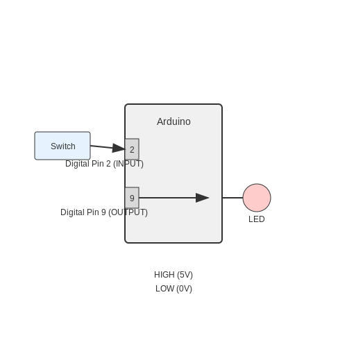
At the core of Arduino programming are digital inputs and outputs (I/O), which allow the Arduino microcontroller to interact with the external world. Digital pins on the Arduino can be configured as either inputs or outputs. An output pin can send a HIGH (usually 5V) or LOW (0V) signal. An input pin can read these states to determine whether the connected devices are toggled on or off.
Digital signals are discrete and binary, represented in two states that align with Boolean logic. This binary architecture simplifies programming and reduces computation costs. For practical applications, consider the control of a motor switch, where digital signals can determine whether the motor is running continuously, intermittently, or not at all.
Setting Up Digital Pins
Before using a digital pin, it must be initialized with the correct mode. The pinMode() function sets a pin as either an input or output. For instance, the following snippet configures pin 9 as an output:
pinMode(9, OUTPUT);Conversely, if you wish to read a digital sensor, initialize the pin as an input:
pinMode(2, INPUT);Reading Digital Inputs
To read the state of a digital input pin, the digitalRead() function is employed. This function returns either HIGH or LOW, which can then be used in conditional statements to control the flow of the program.
For example, to read from a switch connected to pin 2, you might write:
int switchState = digitalRead(2);This state can be utilized to trigger actions, such as lighting an LED based on the switch's position or activating a relay to power larger devices.
Writing Digital Outputs
Writing a signal to a digital pin is just as straightforward. The digitalWrite() function sends a HIGH or LOW signal to a specified pin, thus controlling devices such as LEDs or relays. Here’s how to turn an LED on and off connected to pin 9:
digitalWrite(9, HIGH);  // Turn on the LED
digitalWrite(9, LOW);   // Turn off the LED
Real-World Applications
The implications of digital I/O are vast and varied. From robotics to home automation, digital control underpins countless innovations. For instance, a temperature monitoring system might utilize digital I/O to trigger alarms or relay messages when the temperature surpasses a pre-defined threshold. Furthermore, digital pins can be combined with libraries to expand functionality, enabling complex sequences such as pulse-width modulation (PWM) for dimming LEDs or controlling motor speeds.
Digital communication protocols such as I2C and SPI can also extend the capabilities of Arduino boards by allowing multiple devices to share a single communication line. These protocols rely heavily on the proper management of digital input and output and understanding their fine control can greatly enhance systems integration.
As technologies advance, the scope and capability of digital I/O continue to expand, enabling engineers and developers to create ever more sophisticated and interconnected systems.
3.2 Analog Input and Output
In the realm of microcontroller programming, particularly with Arduino platforms, the manipulation of analog signals plays a pivotal role in bridging the physical world with digital applications. This section delves into the fundamentals and intricacies of analog input and output, showcasing how these capabilities can enhance the functionality of your Arduino projects.
Understanding Analog Signals
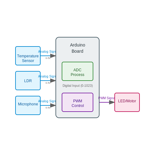
Analog signals are continuous waveforms that represent physical quantities. Unlike digital signals that switch between high and low states (binary values), analog signals can take on any value within a given range. This characteristic is particularly essential in applications such as:
- Temperature sensing: Using thermistors or thermocouples to convert temperature into voltage.
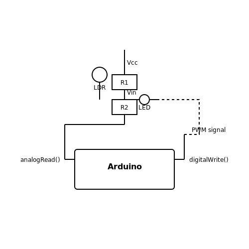
- Light intensity measurement: Employing light-dependent resistors (LDRs) to monitor ambient light changes.
- Sound input: Capturing audio signals with microphones.
The representation of these analog signals allows the Arduino to read, process, and perform operations based on real-world inputs. According to Nyquist's theorem, to avoid losing information in the analog-to-digital conversion process, a signal must be sampled at least twice its highest frequency component.
Analog Input with Arduino
Arduino boards are equipped with analog input pins, typically denoted as A0 to A5 on most boards, which can be used to read the voltage from analog sensors. The process of analog-to-digital conversion (ADC) transforms a continuous voltage into a discrete digital value, ranging from 0 to 1023 (in a 10-bit resolution, typical in Arduino), corresponding to 0V to the reference voltage (often 5V). The equation governing the conversion can be expressed as:
Where:
- ADC_Value is the digital representation (0-1023).
- Analog_Voltage is the voltage measured at the analog pin.
- $$V_{ref}$$ is the reference voltage (typically 5V for most Arduino boards).
To implement an analog input reading in Arduino, the following code snippet can be utilized:
const int sensorPin = A0; // define the analog pin

void setup() {
    Serial.begin(9600); // initialize serial communication
}

void loop() {
    int sensorValue = analogRead(sensorPin); // read the input
    Serial.println(sensorValue); // output the result
    delay(500); // delay for half a second
}
Analog Output with Arduino
The capability of outputting analog signals from an Arduino board is accomplished through a method called Pulse Width Modulation (PWM). Although most Arduino pins are digital, certain pins can simulate analog output using PWM, casting a shadow of the analog signal through rapid switching. This effectively controls various devices such as motors, LEDs, and heaters based on their duty cycles.
The relationship between the duty cycle and the output voltage can be approximated with the following equation:
Where:
- Output_Voltage is the voltage delivered to the load.
- Duty_Cycle is the ratio of the time the signal is high to the total time period (0 to 255 in Arduino).
- $$V_{cc}$$ is the supply voltage (commonly 5V).
Here’s an example of how to create an analog output using PWM in Arduino:
const int ledPin = 9; // define which pin the LED is connected to

void setup() {
    pinMode(ledPin, OUTPUT); // set the ledPin as output
}

void loop() {
    for (int value = 0; value <= 255; value++) {
        analogWrite(ledPin, value); // gradually increase the brightness
        delay(10); // small delay
    }
    for (int value = 255; value >= 0; value--) {
        analogWrite(ledPin, value); // gradually decrease the brightness
        delay(10); // small delay
    }
}
Real-World Applications
The integration of analog input and output in Arduino projects leads to an extensive range of applications, including:
- Home Automation: Monitoring ambient light or temperature to automate lighting and heating systems.
- Wearable Technology: Sensing physiological parameters, like heart rate, where accuracy in analog reading is crucial.
- Robotics: Controlling motors in robotic arms, where pulse width modulation can dictate position, velocity, and torque.
In conclusion, understanding analog input and output paves the way for advanced control systems and real-time data processing in numerous fields, effectively binding the physical world with digital applications across various domains.
3.3 Pulse Width Modulation (PWM)
Pulse Width Modulation (PWM) is a fundamental technique used in electronics to control the power delivered to devices, particularly those with resistive and inductive loads, like motors and LEDs. It involves modulating the width of the pulse in a given period while maintaining a constant frequency, enabling efficient power delivery without generating significant heat. The versatility and efficiency of PWM make it a crucial concept for engineers and researchers engaged in embedded systems and automation.
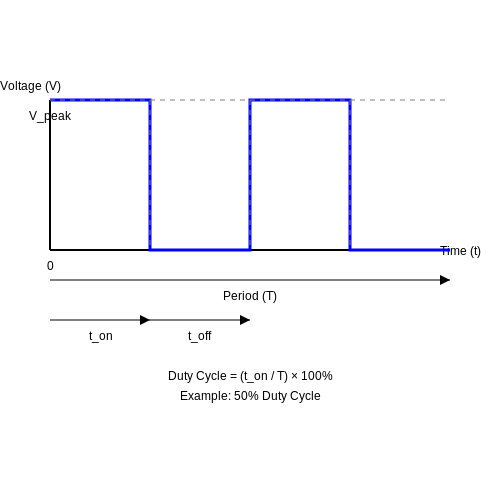
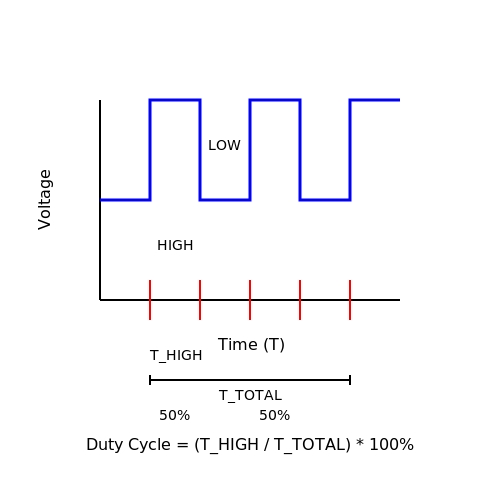
To understand PWM, consider the concept of duty cycle, defined as the ratio of the time the signal is HIGH (active) to the total period of the signal. Mathematically, it is expressed as:
Where:
- THIGH is the time for which the signal is HIGH.
- TTOTAL is the total time period of the PWM signal.
For example, if a PWM signal has a period of 100 ms and is HIGH for 40 ms, then the duty cycle would be 40%. This means that on average, the output voltage is 40% of the supply voltage.
Applications of PWM
PWM is widely utilized in various applications:
- Motor Control: By adjusting the duty cycle, engineers can control the speed of DC motors efficiently while minimizing energy loss.
- LED Dimming: Varying the duty cycle allows for precise control over brightness without changing the LED's color or significantly affecting its lifespan.
- Audio Signal Generation: PWM can synthesize audio signals by varying the width of digital pulses to create sound waves.
Implementing PWM on Arduino
Arduino platforms provide an accessible environment to implement PWM, leveraging its analogWrite function to output PWM signals. The following is a brief overview of how to set up this feature:
- Use analogWrite(pin, value) where pin is the PWM-enabled pin and value is an integer between 0 (0% duty cycle) to 255 (100% duty cycle).
- The frequency of the PWM signal depends on the Arduino model; for most, it remains around 490 Hz or 976 Hz for specific pins.
For example, an Arduino sketch can adjust the brightness of an LED connected to pin 9:
void setup() {
    pinMode(9, OUTPUT); // Set pin 9 as an output
}

void loop() {
    for (int brightness = 0; brightness <= 255; brightness++) {
        analogWrite(9, brightness); // Increase brightness
        delay(10);
    }
    for (int brightness = 255; brightness >= 0; brightness--) {
        analogWrite(9, brightness); // Decrease brightness
        delay(10);
    }
}
This PWM application demonstrates a simple fade effect for an LED, showing how varying the duty cycle effectively controls light intensity.
As we probe deeper into electronics and complex systems, PWM's efficiency and control aspects are pivotal in a variety of domains, including robotics, automotive technologies, and modern consumer electronics.
4. Understanding Arduino Libraries
4.1 Understanding Arduino Libraries
Arduino libraries are essential tools in the Arduino programming ecosystem, playing a crucial role in simplifying complex tasks and enabling rapid prototyping. These libraries provide pre-written code that allows users to easily interface with a variety of hardware components and simplify the implementation of various functionalities, such as controlling sensors, motors, and communication protocols.
Functionality of Arduino Libraries
The primary function of an Arduino library is to encapsulate a set of functionalities related to a specific purpose, allowing programmers to invoke these functionalities without needing to understand the underlying implementation details. For example, libraries designed for sensor interfaces abstract the lower-level communication details, enabling even those with limited programming experience to utilize advanced sensors.
- Modular design: Libraries encourage modular programming, increasing code reusability and maintainability.
- Simplified communication: Libraries streamline communications with peripheral devices, often simplifying I2C, SPI, and UART protocols.
- Abstraction of complexity: They avoid the need for low-level programming, allowing the focus on the application logic instead.
Working with Libraries
Embedding a library in an Arduino sketch is straightforward, facilitated by the #include directive. This command makes all functions and variables defined in the library available to your code, akin to importing a module in other programming languages. For instance:
#include <Wire.h>
#include <LiquidCrystal_I2C.h>

LiquidCrystal_I2C lcd(0x27, 16, 2); // Set the LCD’s I2C address and dimensions

void setup() {
    lcd.begin();
    lcd.print("Hello, Arduino!");
}

void loop() {
    // Your main code here
}
In this example, the Wire library for I2C communication and the LiquidCrystal_I2C library for controlling LCDs are included. The provided code initializes an LCD and displays a simple message.
Library Development
For advanced users interested in creating their own libraries, understanding the underlying structure is vital. A typical Arduino library consists of a header file (.h) and a source file (.cpp). The header file defines the library’s classes and functions, while the source file implements the functionality.
To create a library, consider these steps:
- Define the library’s purpose and functions that the user might require.
- Create the header file with the class definition and public method declarations.
- Implement these methods in the source file, ensuring to handle any necessary initialization and state management.
- Package the library into a folder named after the library, containing both files and a keywords.txt file for syntax highlighting.
Real-World Applications
Arduino libraries are implemented in a multitude of projects, ranging from environmental monitoring systems to robotics and home automation. For instance, the Adafruit Sensor library can interact with various environmental sensors, enabling users to gather temperature, humidity, and pressure data seamlessly. Similarly, libraries available for motor drivers allow users to build more complex robots without delving into intricate details of motor control.
In the realm of educational technology, libraries significantly reduce the complexity of coding for students and professionals, making advanced programming concepts more accessible. Consequently, Arduino libraries serve not just as tools but as gateways to more intricate designs and applications, fostering innovation in various fields.
4.2 Including Libraries in Your Projects
In the realm of Arduino programming, leveraging libraries is crucial for enhancing the functionality of your projects. Libraries provide pre-written code that can save time and simplify complex tasks, allowing you to focus on innovation rather than reinventing the wheel. While understanding the concept of a library is fundamental, the real challenge lies in effectively integrating them into your projects and recognizing their potential impact on project efficiency and capability.Understanding Libraries
A library in the context of Arduino is a collection of pre-written code designed to assist in specific tasks. These can include handling communication protocols, interfacing with sensors and actuators, and even managing complex algorithms. By using libraries, you can access higher-level functionalities without having to delve into the lower-level details. For instance, using a library for a temperature sensor might allow you to obtain temperature readings with just a few lines of code, as opposed to manually configuring the communication and data acquisition processes. Historically, Arduino libraries have evolved alongside the platform itself, starting with simple functionalities and expanding to cover a vast ecosystem of sensors, displays, and connectivity modules. This evolution has made Arduino an accessible option for prototyping and experimentation in various fields, including electronics, robotics, and IoT.Including Libraries in Your Sketch
To include a library in your Arduino project, you typically follow a straightforward process: 1. Select the Library: Identify the library you need. This can be done through the Arduino IDE Library Manager, where you can browse and search for available libraries. 2. Install the Library: If the library is not already installed, you can download it directly through the Library Manager or manually from the library’s GitHub repository. 3. Include the Library in Your Code: Once installed, include the library in your sketch using the `#include` directive at the beginning of your code. Here’s a sample step for including the popular Wire library, which is essential for I2C communication: cpp #includeExample Libraries for Real-World Applications
The choice of libraries can significantly impact the effectiveness of your Arduino projects. Here are a few examples of popular libraries and their applications:- Adafruit Sensor Library: This library is used to simplify the interaction with various sensors that are compatible with Adafruit products. It provides a uniform interface for reading values from different sensor types.
- SPI Library: Utilized for Serial Peripheral Interface communication, this library allows for high-speed data exchange between the Arduino and peripherals like SD cards or displays.
- WiFi Library: Essential for projects involving Internet connectivity, this library makes it easier to connect your Arduino to Wi-Fi networks, enabling IoT applications.
Best Practices for Library Management
Managing libraries wisely is crucial for project stability and maintainability. Here are some best practices: - Keep Libraries Updated: Libraries can receive updates that improve functionalities or enhance performance. Regularly check for updates using the Arduino IDE's Library Manager. - Documentation and Examples: Familiarize yourself with the library documentation and example sketches provided with the library. This can help in understanding the optimal usage of the library. - Consolidate Functionality: Don't overload your projects with multiple libraries that perform similar functions. Stick to the most efficient one to limit the footprint and complexity. In conclusion, the ability to include and manage libraries effectively opens a multitude of possibilities for Arduino projects. By leveraging existing libraries, you can streamline your development process and focus further on innovating and implementing your ideas.4.3 Creating Your Own Functions
In the realm of Arduino programming, functions serve as modular blocks of code that enhance clarity and reusability. Function creation empowers engineers and researchers alike to distill complex operations into manageable segments, fostering a clean and robust codebase. This section delves into the art of function creation, moving seamlessly from simple definitions to intricate applications, thereby cementing your programming prowess.
Understanding Functions in Arduino
A function is essentially a self-contained module that executes a designated task without necessitating knowledge of the code that resides outside its parameters. Functions can accept input values known as parameters and can return a single value, thereby encapsulating functionality with specific input-output behavior. The meticulous structuring of functions allows for an organized and error-minimizing programming experience.
Basic Structure of a Function
The syntax to define a function in Arduino is straightforward and consists of four key components:
- Return Type: Specifies the data type of the value returned by the function. For instance,
int,void,float, etc. - Function Name: A descriptive identifier that conveys the purpose of the function.
- Parameters: A set of input parameters enclosed in parentheses - these are optional.
- Function Body: The code block that defines what the function does, enclosed in curly braces.
The following code snippet illustrates a simple example:
int add(int a, int b) {
    return a + b;
}
Here, the add function takes two parameters, a and b, and returns their sum. This basic function exemplifies the power of abstraction, allowing the main program to utilize add without diving into its implementation details.
Defining Functions with No Return Values
When a function does not return a value, it is declared with the void return type. Such functions are often used to perform tasks such as outputting data or altering the state of components without the need for a returned value. Below is an example:
void blinkLED(int pin, int delayTime) {
    pinMode(pin, OUTPUT);
    digitalWrite(pin, HIGH);
    delay(delayTime);
    digitalWrite(pin, LOW);
    delay(delayTime);
}
The blinkLED function takes a pin number and a delay time as parameters, configuring the pin for output, and blinking an LED connected to it. Such encapsulated functions can be incredibly useful in robotics and embedded applications, allowing for precise control over hardware.
Illustrating Higher-Level Applications
Functions are not merely for organizational convenience; they can also encapsulate sophisticated algorithms that serve real-world applications. For instance, as systems become more complex with sensors and networks, defining clear functions can significantly reduce debugging time.
An example of a more complex application could be found in a temperature monitoring system that utilizes multiple sensor readings. Below is a theoretical structure for such a function:
float readTemperature(int sensorPin) {
    int rawValue = analogRead(sensorPin);
    return (rawValue / 1024.0) * 5.0 * 100; // Converts sensor reading to temperature in Celsius
}
This function reads an analog temperature sensor and returns the temperature in Celsius. By isolating the reading process into its function, the main control loop can request temperature readings without concerning itself with how these readings are computed. This abstraction aids in maintaining clean code as the project grows.
Conclusion
Creating functions is fundamental to professional Arduino programming. Their use promotes not only code reusability and readability but also helps manage program complexity. With rigorous practice and an understanding of how to leverage parameterization and returns, you can architect sophisticated and high-performing embedded systems. As you move forward, consider functions as the building blocks of your code that can lead to unparalleled innovation and efficiency in your projects.
5. Introduction to Serial Communication
5.1 Introduction to Serial Communication
Serial communication is a fundamental technique for data exchange between microcontrollers and peripheral devices. In the context of Arduino programming, it serves as a vital conduit for debugging, sensor data collection, and interfacing with other hardware components. Understanding this mechanism is crucial for advanced users aiming to develop sophisticated projects requiring reliable data exchange.
Overview of Serial Communication
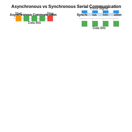
At its core, serial communication involves the sequential transmission of data bits over a single communication channel or wire. This method can be contrasted with parallel communication, where multiple bits are sent simultaneously over multiple channels. The primary benefits of serial communication include reduced wiring complexity and the ability to transmit data over longer distances without significant degradation.
The two most common forms of serial communication are asynchronous and synchronous. In asynchronous communication, data is sent without a clock signal, relying on start and stop bits for synchronization. Conversely, synchronous communication uses a clock signal to synchronize data transmission, allowing for potentially higher speeds and more efficient bandwidth utilization.
Historical Context and Applications
The roots of serial communication can be traced back to the early days of computing and telecommunications. Technologies such as RS-232 and USB have laid the groundwork for modern serial communication protocols. In everyday applications, serial communication can be found in various devices, including GPS receivers, modems, and even computer peripherals, playing a vital role in their functionality.
Implementing Serial Communication in Arduino
To implement serial communication in an Arduino environment, the Arduino IDE offers the Serial class, which provides a straightforward API for transmitting and receiving data. Initialization occurs in the setup() function, where the baud rate—the speed of data transmission measured in bits per second—is established. Common baud rates are 9600, 19200, and 115200, with the former being the most frequently used for basic applications.
Here is an example of initializing serial communication in an Arduino sketch:
void setup() {
    Serial.begin(9600); // Initialize serial communication at 9600 bits per second
}

void loop() {
    Serial.println("Hello, Serial Communication!"); // Send data to the serial monitor
    delay(1000); // Wait for 1 second
}
This code snippet initializes serial communication at a baud rate of 9600 and sends a message to the serial monitor every second. Utilizing the Serial.println() function, it automatically appends a newline character after the data transmission, allowing for clearer outputs on the serial monitor.
Structured messages can be sent over serial to convey more complex data, like sensor readings or status updates, potentially in string or byte formats. This flexibility transforms serial communication into a powerful tool for debugging and data logging in various engineering projects.
Advanced Topics in Serial Communication
Beyond basic use, several advanced concepts can be explored, including:
- Protocol design: Creating custom communication protocols for specific applications to optimize data handling.
- Multi-device communication: Using libraries such as
SoftwareSerialto facilitate communication between multiple devices. - Error detection: Implementing checksums or parity bits to ensure data integrity during transmission.
- Real-time considerations: Techniques for managing latency and ensuring timely data processing in fast-paced applications.
As you delve deeper into serial communication with Arduino, these advanced topics will significantly enhance the sophistication and robustness of your projects, paving the way for future innovations in embedded systems development.
5.2 Using Serial Monitor
The Serial Monitor is one of the most powerful tools available in the Arduino software environment, rendering it essential for real-time data inspection and debugging. When developing complex systems involving sensors, actuators, or wireless communications, you often need to visualize data in real-time to understand system behavior. The Serial Monitor offers a versatile interface for examining variables, logging events, and monitoring system performance.
Understanding the Serial Communication Protocol
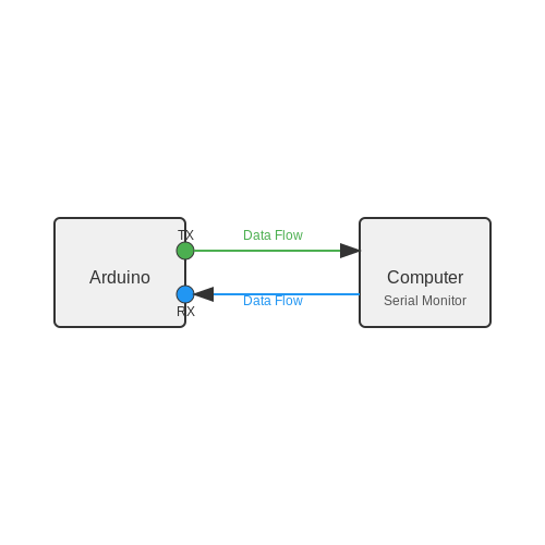
At its core, the Serial Monitor utilizes the UART (Universal Asynchronous Receiver-Transmitter) protocol, which allows for asynchronous serial communication between your Arduino and your computer. This protocol transmits data bytes serially, or one bit at a time, which makes it resource-efficient and simplified for many projects.
In an Arduino board, serial communication is commonly established via the TX and RX pins. A typical configuration involves sending data from the Arduino (TX) to the PC (RX) and vice versa, enabling a two-way communication channel. Understanding this flow is crucial when implementing debugging strategies and ensuring effective communication.
Setting Up the Serial Monitor
To access the Serial Monitor, follow these steps:
- Open the Arduino IDE.
- Connect your Arduino board to your computer via USB.
- Load your sketch (program) into the IDE.
- Click on the Serial Monitor icon, or use the shortcut Ctrl + Shift + M (or Cmd + Shift + M on macOS).
Once opened, the Serial Monitor interface will display incoming messages from the Arduino. You can choose different baud rates (the speed of data transmission) to match the settings defined in your sketch.
Basic Example of Serial Output
In a simple scenario where you wish to output sensor data, you would use the Serial.begin() function in the setup() of your sketch to initialize the communication. For instance:
void setup() {
    Serial.begin(9600); // Set baud rate to 9600
}

void loop() {
    Serial.println("Hello, Serial Monitor!");
    delay(1000); // Wait for 1 second
}
This code initializes serial communication at a baud rate of 9600 bits per second, then continuously sends the string "Hello, Serial Monitor!" to the Serial Monitor every second. This simple output serves as an introductory example for more complex interactions that might involve reading data from sensors.
Advanced Features
Once you are familiar with basic outputs, the Serial Monitor can also be used for more sophisticated tasks such as:
- Debugging complex algorithms by printing relevant variable states, error messages, or exceptions.
- Receiving data from the user via the Serial Monitor, allowing for real-time manipulation of system parameters (e.g., modifying a motor speed based on user input).
- Integrating external libraries for high-level functionalities, such as processing GPS or wireless data.
Example: User Input through Serial Monitor
Here’s a more advanced example where user input modifies behavior:
void setup() {
    Serial.begin(9600);
}

void loop() {
    if (Serial.available() > 0) {
        int inputData = Serial.parseInt(); // Read integer from Serial Monitor
        Serial.print("Received: ");
        Serial.println(inputData);
    }
}
This example will read an integer input given through the Serial Monitor and print it back to the console, demonstrating a simple interaction. Such capabilities are vital for tuning parameters during experimentation.
Practical Applications
The applicability of the Serial Monitor extends beyond mere debugging; it encompasses various sectors including:
- Research Prototyping: Rapidly testing algorithms in sensors and actuators.
- Educational Projects: Visual systems engineering and electronics courses utilize the Serial Monitor as a means to connect theoretical concepts with practical applications.
- IoT Development: Monitoring and debugging data transmission from Internet of Things devices, ensuring robust connectivity.
By effectively leveraging the Serial Monitor, you can significantly enhance the development process, troubleshoot effectively, and optimize your Arduino projects with precision. As you advance your skills, consider how this fundamental tool can integrate with more complex systems and data handling strategies.
5.3 Communicating with Other Devices
In the realm of embedded systems, the ability to communicate with other devices is paramount. Arduino provides several protocols and methods for inter-device communication, enabling seamless integration with sensors, actuators, displays, and other microcontrollers. This section delves into the key communication techniques applicable in Arduino programming, particularly focusing on I2C, SPI, and serial communication.
I2C Communication
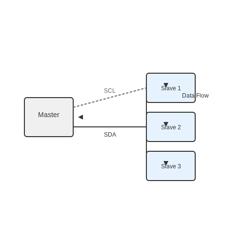
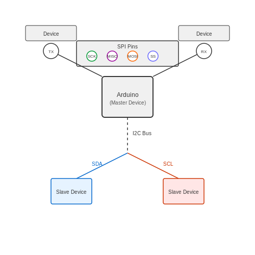
The Inter-Integrated Circuit (I2C) protocol is a two-wire interface that allows multiple devices to communicate with one another using only two lines: a data line (SDA) and a clock line (SCL). This multi-master, multi-slave architecture facilitates efficient communication in systems where several components need to work collaboratively.
One significant advantage of I2C is its simplicity in connecting multiple devices using different addresses. Each device on the I2C bus is given a unique address, which is crucial for ensuring reliable data transmission. The total number of devices on an I2C bus is limited by the number of unique addresses available.
To initiate communication, the master device sends a start condition, followed by the address of the destined slave. Subsequently, data can be sent in a synchronized manner. A typical Arduino setup might resemble the following for initializing I2C:
#include <Wire.h>

void setup() {
    Wire.begin(); // Join I2C bus as master
}

void loop() {
    Wire.beginTransmission(slaveAddress);
    Wire.write(data);
    Wire.endTransmission();
    delay(1000);
}
SPI Communication
The Serial Peripheral Interface (SPI) is another prevalent communication protocol for Arduino, particularly suited for high-speed data transfer. Unlike I2C, SPI requires a minimum of four wires: one for the clock (SCK), one for data input (MISO), one for data output (MOSI), and a slave select line (SS) for each slave device.
SPI operates in a master-slave architecture, where one master controls multiple slaves. The ability to choose which slave is active by toggling the slave select pin enables efficient communication and reduces bottlenecks in data flow.
A simplified example to communicate with an SPI device could be demonstrated through the following code snippet:
#include <SPI.h>

void setup() {
    SPI.begin(); // Initialize SPI
    pinMode(slaveSelectPin, OUTPUT); // Set SS pin
}

void loop() {
    digitalWrite(slaveSelectPin, LOW); // Select slave
    SPI.transfer(data); // Transfer data
    digitalWrite(slaveSelectPin, HIGH); // Deselect slave
    delay(1000);
}
Serial Communication
Serial communication is one of the most straightforward methods for connecting Arduino to other devices, whether it's a computer, another microcontroller, or even a network module. Arduino typically supports asynchronous serial communication using one or more UART (Universal Asynchronous Receiver-Transmitter) interfaces.
The simplicity of serial communication lies in its linear nature- data is sent one bit after another. Moreover, Arduino's Serial library provides an easy way to manage communication. The baud rate, which defines the speed of communication (in bits per second), must be consistent between the communicating devices to ensure proper data transmission.
Here's an example of how to set up basic serial communication using Arduino:
void setup() {
    Serial.begin(9600); // Start serial communication at 9600 baud
}

void loop() {
    Serial.println("Hello, World!"); // Send data
    delay(1000);
}
Learning to communicate with other devices effectively can drastically improve the functionality of your Arduino projects, allowing for the creation of sophisticated and interconnected systems. The choice between I2C, SPI, and serial depends largely on the requirements of the application, including speed, complexity, and the number of devices involved. Engaging with these protocols opens up avenues for real-world applications such as sensor networks, robotic control systems, and even IoT frameworks.
6. Working with Sensors
6.1 Working with Sensors
As we enter the world of Arduino programming, one of the most compelling applications involves integrating sensors. These devices allow for the collection of environmental data and facilitate interaction between the physical world and the digital realm. Understanding the intricate workings of various sensors and how to manipulate them through Arduino programming is crucial for advanced projects, such as robotics, industrial automation, and environmental monitoring.
Understanding Sensors
Sensors are transducers that convert a specific physical quantity into an electrical signal. They respond to various stimuli, such as light, temperature, sound, and motion, effectively transforming analog data into a measurable format. Common sensor types include:
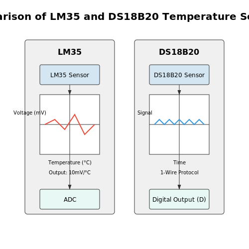
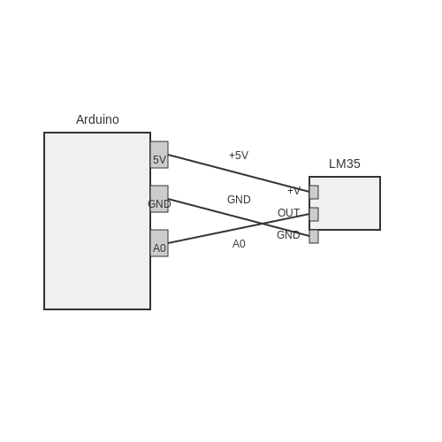
- Temperature Sensors: Such as thermistors and LM35, these convert temperature variations into voltage changes.
- Light Sensors: Devices like the photoresistor or photodiode that detect ambient light levels.
- Motion Sensors: Include passive infrared sensors (PIR) that detect movement based on changes in infrared radiation.
- Pressure Sensors: Such as piezoelectric sensors, converting pressure changes into electronic signals.
Each sensor comes with its specifications, output types, and operational ranges. Therefore, it is essential to refer to the sensor's datasheet for correct implementation and to understand any required calibration procedures.
Interfacing Sensors with Arduino
To interface a sensor with an Arduino, you will typically connect the sensor's output terminal to one of the Arduino's analog or digital input pins. The choice of the pin and method of reading the sensor's data depends on whether the output is analog or digital. For instance:
- Analog sensors output a continuous signal that can be read using
analogRead(pin). - Digital sensors return a binary signal, read using
digitalRead(pin).
The following example demonstrates how to read a temperature sensor's data using the LM35, which has an output of 10 mV per degree Celsius. A typical Arduino setup includes the sensor connected to an analog pin.
Here, \( V_{out} \) is the output voltage from the sensor, and \( T \) is the temperature in degrees Celsius. To convert the voltage back to temperature, you can rearrange the formula as follows:
Example Code Snippet
Below is an Arduino code snippet that reads the temperature from an LM35 sensor and prints it to the serial monitor:
int sensorPin = A0; // select the input pin for the sensor
float temperature;

void setup() {
    Serial.begin(9600); // initialize serial communication
}

void loop() {
    int sensorValue = analogRead(sensorPin); // read the input
    temperature = (sensorValue * 5.0 / 1023.0) * 100; // calculate temperature
    Serial.println(temperature); // print temperature in Celsius
    delay(1000); // wait 1 second before next reading
}
The equivalent analog reading is then converted to a voltage, reflecting the temperature in Celsius. This cycle repeats every second, providing continuous temperature updates.
Advanced Sensor Integration
For applications requiring multiple sensors or more complex data processing, it is beneficial to implement libraries that simplify the integration process. The Adafruit Sensor library, for instance, abstracts away the intricate details of various sensors and offers intuitive functions for data retrieval and processing.
In real-world applications, sensors gather data crucial for decision-making. For instance, in an automated greenhouse, temperature and humidity sensors can work in tandem to trigger ventilation systems when specific thresholds are reached. This synergy between sensors and actuators highlights the importance of programming in control systems design.
In conclusion, understanding how to interface sensors with Arduino is foundational in various engineering and scientific fields. From singular applications to multifaceted systems, the utility of sensors is augmented by adept programming that allows for seamless integration, leading to innovative solutions.
6.2 Integrating Modules (e.g., Bluetooth, Wi-Fi)
As we continue to expand the capabilities of Arduino microcontrollers, the integration of communication modules like Bluetooth and Wi-Fi significantly enhances their functionality. This section delves deep into how these technologies can be programmed and implemented in Arduino projects to facilitate wireless communication.
Understanding Wireless Communication Technologies
Before we dive into the integration process, it's important to understand the communications standards these modules use. Bluetooth operates through short-range radio waves, typically within a 10-meter radius, making it ideal for communicating with nearby devices. In contrast, Wi-Fi utilizes higher frequencies, enabling a broader range and higher data rates, capable of connecting to the internet or local networks.
Integrating Bluetooth Modules
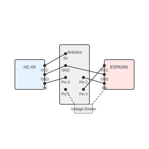
The most commonly used Bluetooth module with Arduino is the HC-05. To integrate a Bluetooth module, you need to establish the correct connections between the module and the Arduino. The HC-05 module typically has four pins: VCC, GND, TX, and RX. Here’s how you can connect the module:
- Connect VCC to the 5V pin on Arduino.
- Connect GND to the GND pin on Arduino.
- Connect TX on the HC-05 to RX (pin 0) on Arduino.
- Connect RX on the HC-05 to TX (pin 1) on Arduino through a voltage divider to limit the 5V signal down to 3.3V since the HC-05 operates at this voltage.
Once the connections are made, you can use the SoftwareSerial library to communicate with the HC-05 module. This library allows you to create a serial communication port on any digital pins.
#include

SoftwareSerial BTSerial(2, 3); // RX | TX

void setup() {
    Serial.begin(9600);
    BTSerial.begin(9600); // HC-05 default speed in communication mode
}

void loop() {
    if (BTSerial.available()) {
        Serial.write(BTSerial.read());
    }
    if (Serial.available()) {
        BTSerial.write(Serial.read());
    }
}
This code initializes the Bluetooth serial communication for data transfer between the HC-05 and the Arduino. In the loop, it checks for incoming data on both sides and relays it accordingly.
Integrating Wi-Fi Modules
The ESP8266 Wi-Fi module has become a favorite among engineers for its versatility and performance. Its integration with Arduino involves similar steps to Bluetooth, albeit with additional complexities due to networking protocols.
To begin with the hardware setup:
- Connect VCC to 3.3V on Arduino.
- Connect GND to GND on Arduino.
- Connect TX on the ESP8266 to RX (pin 2) on Arduino.
- Connect RX on the ESP8266 to TX (pin 3) on Arduino through a voltage divider (as with the HC-05).
For the Wi-Fi integration, the ESP8266WiFi library must be used. The following code snippet demonstrates establishing a Wi-Fi connection and sending data over the network:
#include

const char* ssid     = "your_SSID";
const char* password = "your_PASSWORD";

void setup() {
    Serial.begin(115200);
    WiFi.begin(ssid, password);

    while (WiFi.status() != WL_CONNECTED) {
        delay(1000);
        Serial.println("Connecting to WiFi...");
    }
    Serial.println("Connected to WiFi");
}

void loop() {
    // Add code to send or receive data over Wi-Fi
}
This code establishes a connection to a Wi-Fi network. Once connected, you can extend its functionality to include hosting a web server or sending data to an external server using HTTP protocols.
Practical Applications
The ability to integrate Bluetooth and Wi-Fi modules opens a myriad of practical applications, from simple remote controls to complex IoT (Internet of Things) systems. For instance, a Bluetooth-enabled weather station can communicate readings directly to a nearby smartphone, while a Wi-Fi connected plant monitoring system can send periodic updates to a user interface accessible from anywhere in the world.
In projects where connectivity is essential, understanding how to effectively utilize these modules on Arduino becomes a cornerstone of modern electronic designs.
6.3 Reading and Processing Sensor Data
In the realm of Arduino programming, the ability to read and process sensor data is fundamental for building responsive and intelligent systems. This subsection delves into advanced techniques for interfacing with various sensors, converting their analog or digital signals into usable data, and effectively processing that data for practical applications.
Understanding Sensor Output
Sensors can deliver information in either analog or digital form. Analog sensors provide a continuous voltage signal that corresponds to the physical quantity being measured—such as temperature, light intensity, or pressure. In contrast, digital sensors output discrete signals representing the state of the measured variable, such as a simple binary on/off signal for a motion sensor.
Analog Sensors
The reading from analog sensors can be processed using the Arduino's built-in analogRead() function. This function retrieves a value ranging from 0 to 1023, representing an input voltage from 0 to 5 volts. It is essential to understand the relationship between this digitized value and the actual physical parameter.
To convert the raw data into a meaningful value, the formula can be derived as follows:
Where:
- Vin = Input voltage corresponding to the sensor output.
- Aread = The analog reading from
analogRead(). - Vref = Reference voltage (typically 5V for most Arduino boards).
With this equation, you can convert the reading from the sensor into a meaningful voltage.
Digital Sensors
For digital sensors, the interaction is often simpler, primarily relying on the digitalRead() function to obtain the sensor's state. However, the reliability of reading digital values might necessitate debouncing, especially in the context of mechanical switches or buttons. Implementing a debounce algorithm ensures that an accurate digital signal is captured, preventing erroneous multiple readings due to noise.
Processing Sensor Data
Once sensor data is read, the next step is to process this information to derive actionable insights. This can involve simple threshold comparisons, averaging, or even more complex statistical analyses depending on the application.
Example: Temperature Data Processing
Consider an application for monitoring temperature with a thermistor. After obtaining analog readings, we might want to implement a simple averaging filter to smooth out the readings over time. This can be accomplished by maintaining an array of previous readings and calculating the average:
const int sensorPin = A0; // Pin connected to thermistor
float readings[10]; // Array to hold 10 readings
int index = 0; // Index for storing new readings
float total = 0; // Total of readings
float average = 0; // Average of readings
void setup() {
    Serial.begin(9600);
}
void loop() {
    total -= readings[index]; // Subtract the last reading
    readings[index] = analogRead(sensorPin); // Read from the sensor
    total += readings[index]; // Add the reading to the total
    index = (index + 1) % 10; // Move to the next index
    average = total / 10; // Calculate average
    Serial.println(average); // Print average value
    delay(1000); // Delay 1 second
}
This code snippet demonstrates how to continuously read temperature values, calculate a simple rolling average, and output the result to the serial monitor. Such a method is particularly effective for noise reduction.
Practical Applications
The principles outlined in this section can be applied to a wide range of real-world applications, including:
- Environmental monitoring: Automated systems to track climatic changes using multiple sensors.
- Smart home automation: Devices that respond to environmental conditions such as temperature or occupancy.
- Robotics: Feedback from distance sensors for navigation and obstacle avoidance.
As you delve deeper into Arduino programming, mastering the integration of sensor data is a pivotal skill. With advanced processing techniques, your projects can reach new levels of complexity and functionality, paving the way for innovative solutions in various engineering and scientific domains.
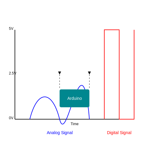
7. Debugging Your Code
7.1 Debugging Your Code
When working with Arduino programming, code debugging emerges as a critical aspect, especially for advanced users who engage in complex projects involving sensors, actuators, and communication protocols. Effective debugging not only addresses code errors but also enhances understanding of how hardware and software interact in a microcontroller environment. Understanding the typical pitfalls is crucial for an efficient debugging process. Logic errors, sensor misreadings, and communication issues are common challenges faced in Arduino development. Therefore, a systematic approach is vital, and it begins with comprehensive implementation of debugging techniques.Understanding Common Errors
Errors in programming can generally be classified into three categories: syntax errors, runtime errors, and logical errors. - Syntax Errors occur when the code violates the rules of programming language structure, such as a missing semicolon or misnested brackets. The Arduino IDE provides line-by-line feedback to assist in identifying these issues early in the coding process. - Runtime Errors occur during execution. For example, if a sensor is disconnected while an attempt is made to read from it, the program will yield an error. Exception handling in more advanced programming languages provides techniques to manage such errors more gracefully, but in Arduino, standard practice involves check conditions before reading sensor values. - Logical Errors are the most challenging. The program compiles and runs without any issues, yet the output does not reflect the intended outcome. Analyzing the logic step-by-step or employing various debugging strategies is crucial for identifying these errors.Strategies for Effective Debugging
Debugging can be approached using several strategies: 1. Serial Output for Diagnostics: Utilizing the `Serial` library enhances debugging by allowing the user to print variable values and program states to the Serial Monitor. For example, before interacting with a sensor, the following can be implemented: cpp Serial.print("Current temperature: "); Serial.println(temperature); This gives insight into variable states without needing to modify the circuit or hardware. 2. Breakpoints and Step-wise Execution: While the Arduino IDE does not natively support breakpoints like traditional IDEs, adding specific `delay()` statements can help simulate a similar environment, giving time to observe LED states or sensor readings after significant events occurring in the program. 3. Using Debug Libraries: Libraries such as `AUnit` can facilitate unit testing within the Arduino environment, allowing for the validation of individual code functions in isolation from the rest of the project. 4. Visual Inspection: Physically inspecting connections can often uncover issues. Ensure that wires are tightened, components are correctly positioned, and no shorts are present. 5. Hardware Debugging Tools: Tools such as oscilloscopes can be critical. For instance, checking the waveform at the output pin rather than just relying on LED feedback can provide clarity when diagnosing communication issues in more advanced projects.Documenting the Debugging Process
Documenting findings during debugging is crucial for future reference and for others who may encounter similar issues. Maintaining a debugging log that includes potential problems, actions taken, and outcomes observed will serve not only as a personal reference but also as a collaborative aid in team settings. In conclusion, debugging in Arduino programming represents a blend of systematic analysis, practical troubleshooting, and a technological understanding of both hardware and software interplay. As projects grow more complex, the need for robust debugging skills becomes indispensable, enhancing both the learning experience and the overall project outcome.7.2 Common Errors and Their Solutions
When diving into Arduino programming, advanced users may encounter various errors that can disrupt their workflow or lead to unexpected behavior in their projects. Understanding these common pitfalls, along with their solutions, is crucial for efficient debugging and ultimately ensures that your projects deliver the desired results. Below, we present a structured overview of frequent errors, supplemented with respective solutions and insights into their implications in real-world applications.Compilation Errors
One of the most frequent issues faced is compilation errors, which usually occur due to syntax mistakes or incorrect library usage. While the Arduino IDE provides helpful error messages, they may not always be straightforward for advanced users. Common causes include:- Missing Semicolons: Failing to terminate lines with a semicolon can halt compiling.
- Typographical Errors: Misspelling function names or variable identifiers leads to 'undefined reference' errors.
- Incorrect Library Inclusion: Not including a library or referencing an obsolete function can cause issues.
Run-Time Errors
Beyond compilation errors, run-time errors can significantly impact project execution. These occur when the code compiles successfully, yet fails when executed. Common causes include:- Out of Bounds Array Access: Attempting to access indices outside the allocated data range can crash programs.
- Null Pointer Dereferencing: Dereferencing a null or uninitialized pointer will lead to unpredictable behavior.
- Inadequate Power Supply: Insufficient power to the Arduino can lead to erratic performance. For example, adding peripherals without considering their current requirements may lead to errors.
Hardware Connection Issues
In working with Arduino, physical connections can also be a source of error, especially when interfacing with external components. Common causes include:- Loose Connections: Inconsistent connections can lead to sporadic readings or complete device failure.
- Incorrect Wiring: Miswiring components to the Arduino, such as incorrect pin mapping for sensors, may produce unpredictable results.
Logical Errors
Perhaps the most insidious type of error is a logical error, where the code compiles and runs correctly without throwing errors, but does not behave as intended. Common causes include:- Incorrect Algorithm Implementation: While the code may run, it may not follow the intended logical flow.
- Improper Use of Data Types: Utilizing the wrong data types can lead to unexpected behavior during calculations. For instance, using integers instead of floats may skew precise computations.
Conclusion
In mastering Arduino programming, it is essential to recognize and troubleshoot these common errors. Each one not only serves as a learning opportunity but also enhances your proficiency in engineering and computing applications. By remaining vigilant and employing methodical debugging techniques, you can innovate effectively and improve your project outcomes. In the journey of development and experimentation, understanding these obstacles strengthens your troubleshooting skills and expands the potential in your projects. Embrace the challenges as stepping stones towards mastering Arduino programming and advancing your technical capabilities.7.3 Best Practices for Code Efficiency
Programming an Arduino can be exhilarating, yet to maximize its potential, particularly in resource-constrained environments, employing effective coding practices is imperative. Efficient code not only improves the performance of your projects but also enhances maintainability and reduces power consumption—an essential factor for battery-operated devices. In this section, we will explore various strategies to optimize your Arduino code. These strategies are grounded in computing principles and highlight their practical relevance through real-world applications.Leverage Built-in Functions and Libraries
One of the powerful features of Arduino programming is its extensive library ecosystem. By utilizing built-in functions and existing libraries, you can significantly shorten your development time and increase code readability. Libraries often contain optimized algorithms that leverage lower-level functions or hardware-specific optimizations. Consider the case of working with a temperature sensor. Instead of manually coding the communication protocol, you can use libraries such as `OneWire` and `DallasTemperature`. These libraries abstract the complexity and provide a straightforward interface:
#include
#include

OneWire oneWire(2);
DallasTemperature sensors(&oneWire);

void setup() {
  sensors.begin();
}

void loop() {
  sensors.requestTemperatures();
  Serial.println(sensors.getTempCByIndex(0));
}
Optimize Loop Timing
In Arduino programming, the `loop()` function is executed repeatedly, which can cause inefficiencies if not managed wisely. To mitigate unnecessary processing, consider the use of non-blocking techniques, such as the `millis()` function, which allows you to check time without halting code execution. This approach is crucial when dealing with multiple tasks, especially in real-time applications. For example, you can read sensor data every 500 milliseconds without blocking the completion of any other tasks, like controlling an LED:
unsigned long previousMillis = 0;
const long interval = 500;

void loop() {
  unsigned long currentMillis = millis();
  if (currentMillis - previousMillis >= interval) {
    previousMillis = currentMillis;
    // Call function to read sensor
  }
}
Minimize Memory Usage
Memory management is especially vital on Arduino due to its limited RAM capacity. Using data types wisely can significantly reduce memory consumption. For instance, instead of using `int` data types where smaller types like `byte` or `char` suffice, you can free up memory resources. To illustrate, changing a variable for RGB colors from `int` to `byte` can cut memory usage dramatically:
byte red = 255;   // Use byte instead of int
byte green = 0;
byte blue = 127;

void loop() {
  setColor(red, green, blue);
}
Effective Use of Control Structures
Using control structures such as if-else statements efficiently contributes significantly to code efficiency. Nesting these statements can quickly become complex and difficult to manage. Instead, you can often refactor your code to utilize `switch-case` constructs, especially when handling multiple conditions on the same variable. Consider a simple example where different actions are taken based on a sensor reading:
switch (sensorValue) {
  case 0:
    turnOff();
    break;
  case 1:
    turnOn();
    break;
  case 2:
    blink();
    break;
  default:
    // Handle unexpected values
}
In Conclusion
The practices highlighted in this section bridge effective programming into the very fabric of Arduino projects, ensuring efficient use of resources while maintaining readability and performance. By leveraging libraries, managing timing, optimizing memory usage, and efficiently structuring control flows, projects can yield better outcomes both in terms of performance and actual functionality. Implementing these practices can drastically alter the way your projects operate, making them not only faster but also easier to debug and extend. As you grow in your Arduino journey, continuously revisiting and refining your code will lead to significant improvements in project outcomes.8. Project Ideas and Inspirations
8.1 Project Ideas and Inspirations
Arduino programming offers a vast landscape for innovation and practical application, particularly for advanced users eager to leverage the platform's capabilities. The bridge between hardware and software paves the way for a multitude of project ideas, each reflecting real-world needs and scientific curiosity. Below are several project inspirations that not only challenge your programming skills but also have practical relevance in their respective fields.
Smart Environmental Monitoring Systems
One compelling project idea is to design a smart environmental monitoring system capable of tracking environmental parameters such as temperature, humidity, and air quality. Utilizing sensors like the DHT22 for temperature and humidity readings, along with an MQ-135 gas sensor for air quality, this project illustrates the integration of HVAC principles and IoT.
Data collected can be sent to a centralized server using Wi-Fi modules such as the ESP8266. By developing a web-based dashboard, users can visualize real-time data, median values, and predictive analysis through a machine learning algorithm, enhancing their understanding of environmental changes.
Wearable Health Monitoring Devices
With advancements in health technology, a wearable health monitoring device that records vital signs (such as heart rate and oxygen saturation) represents another viable project. By employing sensors like the MAX30100, which integrates both heart rate and SpO2 readings, you can create a system that continuously monitors a user’s health metrics.
The data can be processed through Arduino and displayed on an OLED screen. Additionally, implementing Bluetooth communication allows for data relay to a smartphone app, providing users insights into their health trends over time.
Automated Agricultural Systems
Agriculture automation is an area ripe for innovation. Imagine a soil moisture sensing system that automatically activates irrigation processes based on moisture data. Using capacitive soil moisture sensors, an Arduino can monitor soil hydration levels and operate a pump via a relay module when watering is necessary.
This project can not only conserve water but can also be expanded with light sensors to optimize plant exposure to sunlight, combining various sensors to adaptively manage crops.
Robotics and Motion Control
Robotics offers immense potential within the Arduino ecosystem. Building a small robot car that can autonomously navigate obstacles using ultrasonic distance sensors is not only a practical challenge but also necessitates advanced programming skills in control algorithms.
By integrating PID (Proportional, Integral, Derivative) control for speed and turning adjustments, users can achieve smooth navigation. You may opt to incorporate remote control features using an RF module or Wi-Fi, adding a layer of complexity and user interactivity to your project.
Home Automation Systems
As smart home technology becomes ubiquitous, implementing a comprehensive home automation system using Arduino can provide an advanced exploration of IoT devices. A system could include control for lights, appliances, and security features through mobile applications or a web interface.
Utilizing relays for switching, and potentially integrating ESP8266 for Wi-Fi connectivity, allows the system to communicate feedback on device status back to the user. Furthermore, integrating features such as motion detection and remote monitoring enhances the functionality and adaptability of the system.
Conclusion
These project ideas not only enhance your skills in programming with Arduino but also drive innovation in practical applications across various fields—environmental science, healthcare, agriculture, robotics, and home automation. Each project allows for expansion and refinements, enabling continuous exploration into the limitless possibilities that Arduino programming has to offer.
8.2 Step-by-Step Project Development
The Arduino ecosystem, characterized by its accessibility and versatility, provides an ideal platform for executing creative projects that bridge the gap between hardware and software. In this section, we will delve into a systematic approach to develop projects on Arduino, emphasizing an advanced understanding of programming techniques, hardware interfacing, and the iterative design process.
Understanding Project Requirements
The first step in any successful project is to define its objectives clearly. This involves both a functional analysis of the desired outcomes and a technical assessment of the resources available. Consider the necessary sensors, actuators, and modules required for the project. For instance, if you are creating a weather station, you might need:
- Temperature and Humidity Sensors: For environmental data collection.
- Wi-Fi/Internet Module: To send data to a server or a cloud service.
- LCD Display: To visually represent the collected data.
Clearly outlining these components will help inform both your programming and hardware integration strategies.
Prototyping and Breadboarding
Before final coding, building a prototype provides invaluable insights. Utilizing a breadboard allows the rapid assembly of circuits without soldering, enabling you to test functionality and tweak configurations on the fly. During this phase, focus on the following:
- Component Testing: Test each component individually to ensure they function correctly and are compatible.
- Connectivity: Confirm that each hardware piece communicates effectively with the Arduino, using basic code snippets to validate their operation.
Once your breadboard prototype is functional, document specific pin configurations, as these will directly translate into your final code setup.
Code Development Strategy
With the hardware in place, attention turns to coding. Here, an iterative approach is vital. Start small: write code to handle a single component, like reading temperature data. This manageable chunk allows you to debug and adjust before moving on to more complex functionalities, such as integrating multiple components.
Utilize modular programming practices by creating functions for different tasks. For example:
- Data Acquisition Functions: Functions that read data from the sensors.
- Display Functions: Functions responsible for updating the LCD or web interface.
Each function should handle its own errors, thus facilitating easier troubleshooting later in the project when issues are likely to arise. Implementing procedures such as error handling and time delays correctly can further enhance system reliability.
Testing and Debugging
As any experienced engineer understands, the debugging process is critical and often iterative. Employ the following techniques during this stage:
- Serial Monitor: Use the Arduino Serial Monitor to output variable states and error messages, providing insights into system behavior in real-time.
- Breakpoints: Introduce breakpoints in the code to pause execution and inspect variable states.
These practices will help narrow down the causes of unexpected behavior. Systematic testing can verify whether each component and function performs as intended.
Final Integration and Deployment
Upon successful testing of the individual components, the next step involves integrating everything into a cohesive unit. This may require further testing to ensure that the interactions between components function seamlessly. Following integration, finalize the code structure, ensuring that naming conventions and comments are clear and informative for future reference.
Finally, upon achieving satisfactory results on the breadboard, consider designing a PCB for a more permanent solution if your project requires enhanced durability or fidelity. This transition signifies the shift from concept to a tangible product ready for real-world applications.
Real-World Applications
The methodologies outlined in this section are not just theoretical; they have been employed in various advanced applications. For instance, automated agricultural systems leverage Arduino in sensors and actuators to optimize irrigation, improving crop yields while conserving resources. Similarly, smart home projects integrate Arduino with IoT capabilities, allowing users to monitor and control home systems remotely, enhancing energy efficiency and convenience.
By following the step-by-step approach detailed above—defining project objectives, prototyping, coding, testing, and finally integrating—you can harness the full potential of Arduino for innovative solutions in diverse domains.
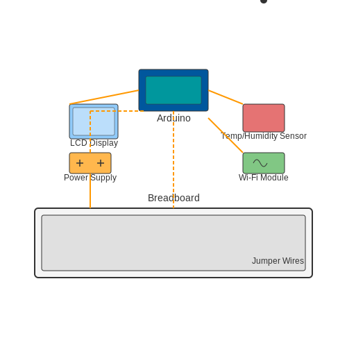
8.3 Prototyping and Testing
Prototyping and testing are fundamental components of the Arduino programming process, especially for advanced engineers and researchers looking to develop robust electronics systems. This section elaborates on effective prototyping strategies and methodologies for rigorous testing, emphasizing their importance in ensuring system reliability and performance.
Prototyping Techniques
Prototyping allows for the exploration of design ideas and involves the creation of a preliminary model that represents the final product. The iterative nature of prototyping aids in identifying flaws and refining functionality before committing to final designs. Here are several advanced prototyping techniques:
- Breadboarding: Utilize a breadboard for rapidly developing and testing circuits. This allows for easy modifications—crucial during the experimental phase.
- Rapid Prototyping Tools: Tools such as CAD and simulation software can visually outline system designs and functionality, assisting in both electronics and software design.
- 3D Printing: For mechanical components involved in Arduino projects, 3D printing can produce enclosures or supports, providing physical context for electronic components.
Testing Strategies
Once the prototype is developed, thorough testing is essential to verify the design's functionality. Advanced testing ensures that the system operates as intended while meeting safety and performance standards. To conduct rigorous testing, engineers should follow structured methodologies:
Unit Testing
Unit testing focuses on validating individual components of the code. Each part of an Arduino sketch can be isolated and tested independently, ensuring that algorithms function correctly. Using frameworks such as Arduino Unit can facilitate these tests.
Integration Testing
After unit tests confirm that individual components work correctly, integration testing combines these units to check if they function together as expected. This is essential as interactions between different components can introduce unexpected behaviors.
System Testing
This broader testing phase assesses the entire system's performance against the specifications. Real-world scenarios should be simulated during this phase to validate overall functionality. Considerations such as load, stress, and boundary condition testing are critical here, ensuring that all aspects work harmoniously under various conditions.
Real-World Applications
Prototyping and testing are not just theoretical constructs; they are practiced rigorously in numerous advanced projects. For instance, in robotics, proactive testing of sensors and actuators is crucial for maintaining operational reliability in dynamic environments. In IoT (Internet of Things) applications, prototypes enable engineers to explore network connectivity issues and power consumption—vital for battery-operated devices.
Conclusion
Prototyping and testing in Arduino programming allow for effective verification of concepts and designs, enabling engineers to mitigate risks before deployment. Mastering these techniques is essential for developing sophisticated electronics systems, enhancing both innovation and project success.
9. Using Timers and Interrupts
9.1 Using Timers and Interrupts
In the realm of Arduino programming, timers and interrupts provide powerful mechanisms for managing time-sensitive operations and responding to events without delay. They are essential tools that help create responsive applications that can handle multiple tasks efficiently, which is particularly pertinent in embedded systems design.
Understanding Timers
Arduino boards utilize hardware timers to keep track of time and generate periodic events. Each timer can operate independently of the main program flow, allowing tasks to be triggered at regular intervals. This independence is crucial for applications such as generating PWM signals, creating timed delays, or measuring elapsed time.
The most commonly used timers on Arduino boards are the Timer0, Timer1, and Timer2. Each timer has its own set of registers that control its behavior, including modes of operation and prescalers. For instance, Timer0 is typically used for functions like millis() and delay(). Understanding the specific functionalities of each timer is vital when managing clock cycles accurately in your application.
Setting Up a Timer
To configure a timer, you need to set up the appropriate registers. Here’s a simplified breakdown of how to initialize Timer1 for a 1-second interval:
In the above equation, Toverflow is the timer overflow time, prescaler is the division factor of the incoming clock signal, and FCPU is the clock frequency of the microcontroller. You can configure the prescaler to achieve higher precision in timing.
For example, assuming a typical Arduino running at 16 MHz and setting the prescaler to 64, we can calculate:
This means that Timer1 will overflow roughly every 1 ms. To achieve a 1-second interval, you would count the number of overflows and trigger an event accordingly.
Utilizing Interrupts
Interrupts are events that temporarily halt the execution of the current program to allow a special function called an interrupt service routine (ISR) to be executed. This is particularly useful when immediate action is required, such as reacting to a button press or a sensor signal.
The primary types of interrupts are external and timer interrupts. External interrupts are triggered by hardware signals, while timer interrupts are generated based on timer configurations. For example, to trigger an interrupt on a rising edge of a digital pin, you can utilize the following function:
attachInterrupt(digitalPinToInterrupt(pin), ISR, RISING);
This will link the chosen pin to the ISR, which executes when a rising edge signal is detected. This approach is fundamental in real-time applications where quick responses are essential for accurate performance.
Real-world Applications
The practical applications of timers and interrupts in Arduino programming are multifaceted:
- Robotics: Allow motors to perform precise movements without interruptions in control and sensing.
- Data Logging: Collecting sensor data at fixed intervals, independent of the main program execution time.
- Power Management: Putting the microcontroller into a low-power state between interrupts to conserve energy.
Overall, mastering timers and interrupts expands your ability to create responsive and efficient Arduino-based applications, showcasing the true potential of microcontroller programming.
Conclusion
As you dive deeper into Arduino programming, understanding how to effectively utilize timers and interrupts will empower you to build more sophisticated projects. These components not only enhance the real-time responsiveness of your applications but also allow you to integrate complex functionalities that demand precise timing and event handling.
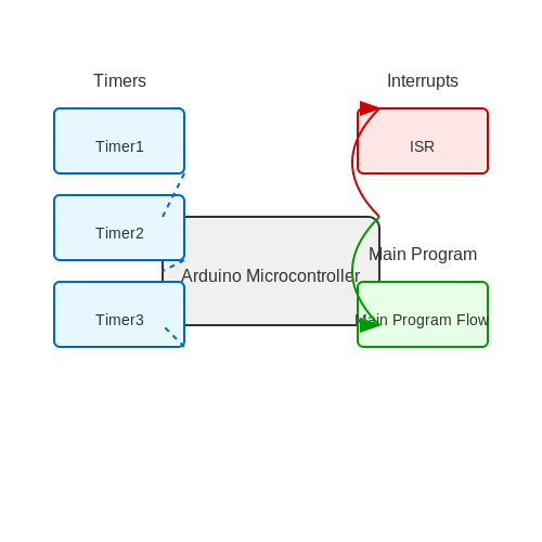
9.2 Implementing State Machines
State machines are powerful conceptual models that significantly enhance the ability to manage complex system behavior in an organized fashion. Through defining a finite number of states and transitions between them, they provide a structured approach to handle various modes of operation, making them indispensable in both theoretical studies and practical applications—especially within the realm of microcontroller programming such as Arduino.
This section delves into the implementation of state machines using Arduino, exploring various methodologies and real-world applications that illustrate their robustness and versatility.
Understanding State Machines
A state machine consists of a finite number of states and a transition function that dictates how the system moves from one state to another based on input conditions. Typically defined as Mealy and Moore machines, the main difference lies in when outputs are produced: immediate transitions based on input or state-dependent outputs, respectively.
Consider the example of a traffic light control system: the states might include Green, Yellow, and Red, with transitions based on timing or sensor input, allowing for smooth operation and safety management at intersections.
Implementing State Machines in Arduino
To implement a state machine on an Arduino, we can utilize a basic structure involving enumeration of states and a loop function that checks for transitions. This method provides clarity and maintainability, especially as systems become complex.
Here is a basic example of how to set up a state machine for a simple LED blinking application:
enum State {OFF, ON};
State currentState = OFF;

void setup() {
    pinMode(LED_BUILTIN, OUTPUT);
}

void loop() {
    switch (currentState) {
        case OFF:
            digitalWrite(LED_BUILTIN, LOW);
            delay(1000);
            currentState = ON;
            break;
        case ON:
            digitalWrite(LED_BUILTIN, HIGH);
            delay(1000);
            currentState = OFF;
            break;
    }
}
In this code snippet, we define two states: OFF and ON. The state changes every second, toggling the built-in LED light on and off. The use of the switch-case structure makes the transitions clear, allowing for easy updates or additions, such as new states for blink patterns or responsiveness to external conditions.
Advanced State Machine Patterns
As applications grow, handling numerous states and transitions may become complex. In such cases, maximum efficiency can be achieved via structured approaches, such as:
- State Pattern Design: Utilizes class encapsulation to separate state behaviors, which simplifies managing interactions and transitions.
- Event-driven State Machines: Employs interrupts and event listeners allowing the system to react immediately to changes, improving responsiveness in user-interactive or real-time environments.
For instance, if your system required the LED to respond not only to time but also to a button press, implementing an event-driven model could better accommodate this functionality.
Real-World Applications
State machines are pivotal in various applications, including:
- Automated industrial control systems, where different operational modes must be managed and transitioned.
- Embedded systems in vehicles, such as managing different states of engine function or safety systems.
- Robotics, where robots switch between states responsive to environmental feedback while executing tasks.
By leveraging state machines, systems can implement complex operational logic while maintaining clear, manageable code structures that facilitate enhancements or troubleshooting.
Conclusion
Implementing state machines in Arduino programming not only streamlines the development process but also optimizes performance across various applications. With flexibility and structured management of states, engineers and developers can create responsive, efficient, and maintainable systems, paving the way for sophisticated innovations in embedded electronics.
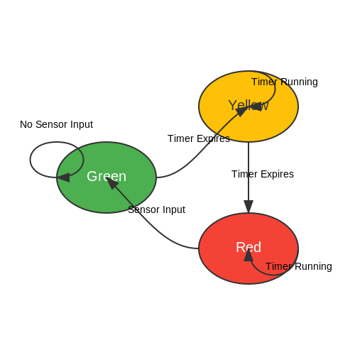
9.3 Exploring Object-Oriented Programming in Arduino
Object-Oriented Programming (OOP) is a paradigm that allows for the organization and manipulation of complex systems through the use of objects that encapsulate both data and behavior. In the context of Arduino programming, OOP facilitates modular, reusable, and maintainable code that can handle intricate interactions with hardware more effectively. This subsection delves into the principles of OOP as applied to Arduino, illustrating how they can enhance the development process for advanced applications.
Understanding the Fundamentals of OOP
At its core, OOP revolves around four main principles: encapsulation, inheritance, polymorphism, and abstraction. Each principle plays a crucial role in the design and structure of an application.
- Encapsulation: This principle bundles the data (attributes) and methods (functions) that operate on the data into a single unit or class, making it easier to manage and protect the integrity of the data.
- Inheritance: Inheritance allows one class (the child) to inherit properties and methods from another class (the parent), enabling code reusability and the creation of hierarchical relationships.
- Polymorphism: Polymorphism permits objects to be manipulated in varied ways, depending on their class type, enhancing flexibility within the code.
- Abstraction: Abstraction involves simplifying complex reality by modeling classes based on the essential properties and behaviors relevant to the application, reducing complexity.
Implementing OOP in Arduino
To illustrate the practical application of OOP concepts in Arduino, consider the creation of a simple class to manage a temperature sensor. For this example, let’s define a class called TemperatureSensor that encapsulates methods for reading temperature data and performing basic calculations. Below is a breakdown of how this class can be constructed and utilized.
class TemperatureSensor {
  private:
    int pin;

  public:
    TemperatureSensor(int inputPin) {
      pin = inputPin;
      pinMode(pin, INPUT);
    }

    float readTemperature() {
      int rawValue = analogRead(pin);
      return (rawValue * 5.0 / 1023.0) * 100.0; // Convert to Celsius
    }
};
In this TemperatureSensor class:
- The constructor initializes the sensor pin and sets it to input mode.
- The readTemperature method reads the analog value and converts it to Celsius, demonstrating encapsulation by hiding the implementation details from the user.
To utilize the class in an Arduino sketch, you would instantiate an object of TemperatureSensor and invoke its methods, as shown below:
TemperatureSensor sensor(A0);

void setup() {
  Serial.begin(9600);
}

void loop() {
  float temp = sensor.readTemperature();
  Serial.print("Temperature: ");
  Serial.println(temp);
  delay(1000);
}
This code snippet demonstrates the practical utility of OOP in Arduino. By defining a class, the temperature reading logic is encapsulated, allowing for cleaner main code and improved maintainability over time. This approach is particularly beneficial in complex projects where multiple sensors or devices can be modeled as distinct objects.
Real-World Applications of OOP in Arduino
Adopting OOP in your Arduino projects can significantly enhance scalability and collaboration. In environments such as robotics, IoT, and complex sensor networks, where multiple components interact with varying functionalities, OOP principles help streamline both development and debugging processes. For instance:
- Robotics: OOP can be employed to control different robot parts (e.g., motors, sensors) as distinct entities, without having to mix their functionalities with the main controlling logic.
- IOT Applications: Devices can be categorized into classes based on their functionalities—sensors, actuators, communication modules—allowing for easier protocol adaptation and network management.
- Simulation Software: In environments that allow for algorithm testing with Arduino hardware, OOP can encapsulate various simulation aspects, leading to modular and reusable code.
Overall, OOP is a powerful technique that enhances the flexibility and robustness of Arduino programming, enabling complex interactions through organized and reusable code structures.