Electrical Grounding and Earthing
1. Definition and Importance of Grounding
1.1 Definition and Importance of Grounding
Grounding, often referred to as earthing in certain regions, is a fundamental practice in electrical engineering and physics, encompassing the connection of electrical circuits to the earth or a conductive body that serves as a reference point. The primary objective of grounding is to ensure safety, protect equipment, and maintain the integrity of electrical systems. However, the significance of grounding extends beyond mere safety measures; it also plays a crucial role in the reliability and performance of electrical systems.
Understanding Grounding
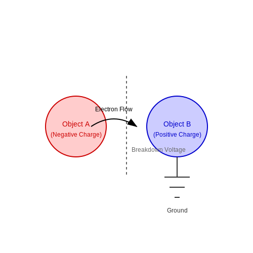
At its core, grounding serves as a direct physical connection that allows for the discharge of excessive electrical energy safely into the ground. By establishing this connection, electrical systems can avoid potential hazards associated with fault currents, static electricity, and lightning strikes. Grounding provides a low-resistance path that facilitates the safe dissipation of overvoltages, thus preventing equipment damage and ensuring the safety of personnel operating close to electrical installations.
The concept of grounding can be categorized into several types, including:
- Equipment Grounding: Involves connecting non-current-carrying conductive parts of equipment to ground to prevent electrical shock.
- System Grounding: Refers to grounding a portion of an electrical system to stabilize voltage levels during normal operation.
- Signal Grounding: Ensures a common reference point for signal voltages in communication systems, which is critical for minimizing noise and interference.
Significance of Grounding
The importance of grounding manifests through several critical aspects:
1. Safety
Grounding is essential for the protection of both human life and equipment. By providing a safe conduit for fault currents, the risk of electrical shock is significantly reduced. Ground-fault circuit interrupters (GFCIs) are prime examples of devices that enhance safety by breaking the circuit when a ground fault occurs.
2. Equipment Protection
Electrical equipment is susceptible to damage from transients, such as voltage spikes caused by lightning or switching operations. Effective grounding strategies, such as using surge protectors and incorporating grounding electrodes, mitigate damage risks, prolonging the lifespan of electrical systems.
3. Circuit Stability
Grounding stabilizes voltage levels within an electrical system, providing a reference point that helps in maintaining balanced and reliable operations. Proper grounding can prevent voltage fluctuations that may lead to system failures or inefficiencies.
4. Compliance with Standards
Adhering to established grounding practices is often a regulatory requirement. Compliance with standards outlined by organizations such as the Institute of Electrical and Electronics Engineers (IEEE) and the National Fire Protection Association (NFPA) ensures that electrical installations are safe and effective, aligning with best practices in the industry.
Real-World Applications
The principles of grounding are applied across various industries. In residential settings, grounding is integrated into electrical installations and appliances to enhance safety. In industrial environments, grounding plays a vital role in protecting sensitive machinery, ensuring uninterrupted operation of power systems, and safeguarding against lightning strikes. Moreover, telecommunications infrastructure relies heavily on grounding to reduce noise in signal transmission and to protect circuits from surges.
As technology advances, the methods and technologies associated with grounding have evolved. Innovations such as ground-enhancing compounds and advanced grounding technologies help in minimizing ground resistance and improving fault current handling capabilities. Understanding the fundamentals of electrical grounding is essential for engineers and technicians to design effective systems and prevent potential hazards.
1.2 Types of Electrical Grounding
Understanding the different types of electrical grounding is essential for engineers and researchers who are engaged in designing and maintaining electrical systems. Each grounding method plays a distinct role in ensuring safety, improving equipment performance, and minimizing electromagnetic interference (EMI) in both industrial and residential settings.
1.2.1 Direct Grounding
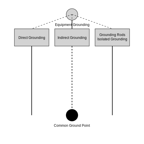
Direct grounding, often referred to as system grounding, involves connecting one point of an electrical system directly to the ground. This method is prevalent in electrical power distribution systems, where a neutral conductor is connected to the ground. The primary purpose of direct grounding is to provide a low-resistance path for fault currents, thereby protecting both personnel and equipment from electrical shock and damage.
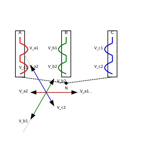
For instance, in a typical three-phase system, the neutral point is grounded to ensure that, in the event of an insulation failure, the fault current flows safely to the ground. Direct grounding enhances the system's stability, facilitating the quick operation of protective devices like circuit breakers and fuses.
1.2.2 Indirect Grounding
In contrast, indirect grounding—also known as functional grounding—does not establish a direct electrical connection to the ground. Instead, this method uses grounding to facilitate the correct operation of appliances without providing a path for fault currents. Indirect grounding is commonly seen in sensitive electronic devices and communication systems where ground loops are a potential issue.
This method mitigates risks such as electrical noise and interference while maintaining an operational reference point. For example, in audio equipment, functional grounding might prevent hum and noise interference from affecting sound quality.
1.2.3 Grounding with Grounding Rods
In many residential and commercial installations, grounding rods are employed as a means of grounding. These rods, typically made of copper or galvanized steel, are driven deep into the earth to create a reliable connection with the ground. This not only dissipates fault currents but also helps protect equipment from lightning strikes and other transient surges.
The effectiveness of grounding rods depends on various factors, including soil resistivity and moisture content. A grounding system using rods must adhere to established safety codes, such as NEC (National Electrical Code) in the U.S., which specify the minimum depth and material requirements for grounding electrodes.
1.2.4 Isolated Grounding
Isolated grounding is another crucial system, particularly in environments with sensitive electronic equipment. This method involves running a separate grounding conductor from the equipment directly to a grounding point, isolated from the regular grounding system. This approach aims to reduce ground loop currents that can interfere with sensitive signals.
For example, in medical facilities where precision equipment is used, isolated grounds can help eliminate noise that may arise from other devices, ensuring accurate readings and effective operation.
1.2.5 Grounding of Equipment
Additionally, proper grounding of equipment is vital for ensuring safety in electrical installations. Equipment grounding typically involves connecting the non-current-carrying metal parts of electrical equipment to the ground. This provides a safe path for errant currents due to insulation failure or other faults.
Through these various grounding methods, electrical systems can be made safer, more efficient, and resilient against faults. Understanding the nuances between these types is essential for any engineer or researcher managing electrical installations.
1.3 Ground Potential and Electrical Safety
Ground potential refers to the electrical potential of the ground relative to some reference point, typically an earth ground. Understanding ground potential is crucial for ensuring electrical safety, especially in an era where electrical systems are ubiquitous in our daily lives. This section delves into the intricacies of ground potential, its implications for safety, and relevant mathematical considerations, ultimately linking back to practical applications in engineering and safety protocols.
Understanding Ground Potential
In electrical installations, ground potential is not just an arbitrary value; it can significantly influence the performance of electrical equipment and the safety of personnel. The ground acts as a common reference point for various electrical systems. However, discrepancies in ground potential can lead to dangerous situations such as electric shocks or system failures.
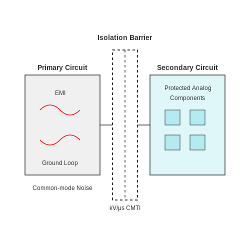
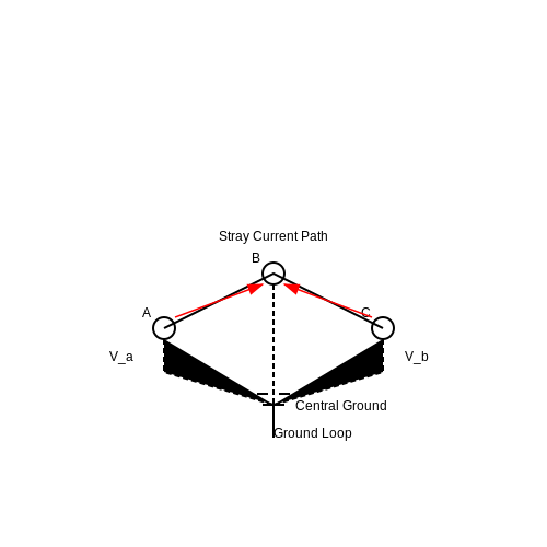
When multiple grounding systems are involved, the phenomenon known as "ground loops" can arise, which occurs when there are differences in ground potential between various grounding points. The presence of a voltage difference can create unwanted currents, potentially damaging sensitive equipment and posing serious safety risks. To visualize these concepts, imagine a simple circuit with multiple ground connections at different potentials, where stray currents can flow unexpectedly.
Mathematical Representation of Ground Potential
To express ground potential mathematically, we can consider the potential difference \( V \) between two points in an electrical network, which can be defined as:
Here, \( V_{a} \) is the potential at point a, and \( V_{b} \) is the potential at point b. In grounding systems, points may vary significantly, prompting the need for systematic evaluation to ensure that the potentials are suitably balanced.
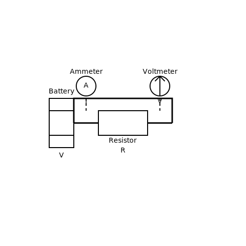
When performing safety analysis, Ohm's law often applies, such that
where \( I \) is the current flowing through the grounding system, \( V \) is the voltage difference due to potential, and \( R \) is the resistance of the grounding pathway. Understanding these values allows engineers to calculate safe current levels, ensuring that fault conditions do not lead to hazardous situations.
Practical Relevance of Ground Potential in Safety Protocols
In practical applications, engineers must adhere to rigorous standards when designing and implementing grounding systems. The National Electrical Code (NEC) offers guidelines on grounding to protect against shock and ensure that electrical systems operate reliably.
Moreover, considering ground potential is vital when addressing electromagnetic interference (EMI) and static discharge concerns. By stabilizing ground potential and mitigating differences, systems can operate more effectively and reduce the risk of performance disruptions.
Case Studies in Electric Safety
Historically, there have been significant incidents caused by inadequate grounding and mismanagement of ground potential. Notably, the 2003 Northeast blackout affected millions, partly due to failures in electrical grounding systems. This event underscored the critical nature of understanding and maintaining appropriate ground potential in ensuring electrical safety.
More recently, industries have adopted advanced grounding techniques and monitoring systems to mitigate risks, showcasing the ongoing evolution of standards in response to such incidents.
In conclusion, ground potential is a fundamental aspect of electrical safety. A solid grasp of this concept equips engineers and safety personnel to implement effective grounding solutions, thereby protecting lives and improving system reliability across a variety of applications.
2. Grounding Electrode Systems
2.1 Grounding Electrode Systems
Electrical grounding and earthing are crucial concepts in electrical engineering and safety, providing a reference point in electrical systems and protecting both equipment and users from faults. Among the foundational elements of grounding is the Grounding Electrode System (GES), which forms the bridge between electrical systems and the earth.
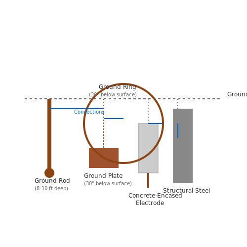
The GES comprises various components that together facilitate the dissipation of excess electrical charge, ensuring safety and operational reliability. The primary components of a GES include grounding electrodes, conductors, and connections.
Types of Grounding Electrodes
Grounding electrodes can be classified into several categories, based on their design and function:
- Ground Rods: Typically made of copper or galvanized steel and driven into the earth to provide a low-resistance path.
- Ground Plates: Plates buried horizontally underground to provide larger surface area contact for grounding.
- Concrete-Encased Electrodes: Reinforcing bars (rebar) within concrete foundations serve as effective grounding electrodes.
- Structural Steel: Metal frameworks of buildings can also be used for grounding when adequately bonded.
- Ground Rings: A loop of conductor buried around a structure. This is effective in reducing ground potential differences.
Importance of Grounding Electrode Systems
A well-designed GES ensures that electrical systems function correctly while providing a critical safety mechanism. The major purposes of grounding systems include:
- Equipment Protection: By providing a low-resistance path for fault currents, a GES mitigates damage to electrical devices from surges and faults.
- Human Safety: Grounding minimizes shock hazards by preventing voltage buildup on exposed conductive parts.
- System Stability: A reliable grounding system stabilizes voltage levels and improves the reliability of sensitive electronic equipment.
Design Considerations
When designing a GES, several factors come into play, including:
- Soil Resistivity: The resistivity of the soil in which the electrodes are placed significantly affects the GES performance. It's often measured in ohm-meters and varies based on moisture content, temperature, and soil type.
- Electrode Size and Depth: Larger and deeper electrodes generally provide lower resistance, but installation can be restricted by soil and environmental factors.
- Regulatory Standards: Compliance with local codes, such as the National Electrical Code (NEC) in the United States, is mandatory for safety and legality.
Mathematical Analysis of Grounding Resistance
The effectiveness of a grounding electrode can be evaluated using the formula for grounding resistance:
Where:
- $$R_g$$ is the grounding resistance
- $$\rho$$ is the soil resistivity
- $$L$$ is the electrode length
- $$D$$ is the distance between electrodes (if multiple electrodes are present)
- $$r$$ is the radius of the grounding electrode
This equation exemplifies how environmental conditions and electrode design critically impact grounding system efficiency. Understanding this relationship allows engineers to optimize grounding configurations based on site-specific conditions.
Finally, evaluating various grounding electrode configurations through simulations and field tests has led to advancements in grounding technology, further enhancing the safety and reliability of electrical systems across various applications, from residential to commercial and industrial installations.
2.2 Masonry and Concrete Grounding
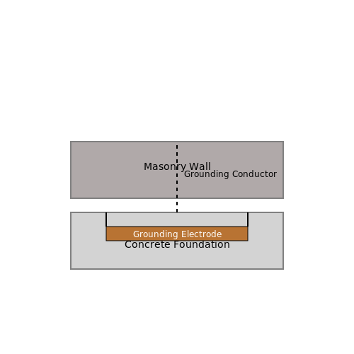
The integration of masonry and concrete grounding systems in electrical engineering has become increasingly relevant as industries seek reliable, low-resistance grounding solutions. This subsection delves into the intricacies of using masonry and concrete as grounding mediums, examining their electrical properties, structural benefits, and practical implementations in contemporary electrical systems.
Understanding Masonry and Concrete in Grounding
Masonry refers to the construction of structures using individual units laid in mortar. Concrete, on the other hand, is a composite material made from a mixture of cement, aggregate, and water that hardens over time. Both materials are widely used in construction and come with unique electrical characteristics that can be effectively harnessed in grounding systems.
One of the primary advantages of using masonry and concrete for grounding is their inherent capacity to provide a stable and resistive path to the earth. When combined with grounding electrodes, such as copper or galvanized steel, they form an integral part of grounding systems that ensure safety and functionality in electrical installations.
Electrical Properties of Masonry and Concrete
The electrical resistivity of concrete, typically ranging between 1,000 to 10,000 ohm-cm, varies depending on its composition and moisture content. Masonry materials such as brick and stone also contribute varying resistive values based on their density and moisture levels.
The resistivity of concrete and masonry can be further analyzed using the formula:
In this equation:
- R is the resistance (ohms).
- ρ (rho) is the resistivity of the material (ohm-meters).
- L is the length of the material through which current flows (meters).
- A is the cross-sectional area through which current flows (square meters).
Using this formula, engineers can calculate the optimal length and cross-sectional area of grounding electrodes embedded within concrete or masonry, thereby ensuring minimal resistance and enhanced safety in electrical systems.
Practical Implementation of Masonry and Concrete Grounding
In practice, concrete foundations and masonry walls are often utilized as grounding systems due to their robust nature and structural integrity. Common applications include:
- Reinforced Concrete Columns: These structures can act as grounding electrodes, effectively distributing electrical charges during a fault condition.
- Grounding Plates: Copper or copper-alloy grounding plates can be embedded in concrete during the pouring process to create an integral grounding solution.
- Masonry Brick Walls: By properly connecting grounding conductors to brick masonry, engineers can harness its resistive properties to reduce electrical noise and provide a safe discharge route for fault currents.
Moreover, the longevity of masonry and concrete ensures that the grounding systems remain effective over time. The inherent durability of these materials allows for maintenance-free solutions in many circumstances, making them ideal in long-term installations, particularly in harsh environmental conditions.
Case Studies in Masonry and Concrete Grounding
Case studies demonstrating successful implementations of masonry and concrete grounding systems underscore their efficacy. For instance, facilities such as data centers and manufacturing plants frequently employ embedded grounding solutions in their concrete structures to significantly reduce the risk associated with electrical faults. These installations often yield measurable improvements in operational reliability and personnel safety.
In conclusion, the use of masonry and concrete in grounding applications combines structural functionality with electrical efficacy. As technology continues to evolve, understanding the benefits and applications of these materials will remain a vital aspect of advancing safe electrical engineering practices.
2.3 Driven Ground Rods and Plates
Electrical grounding and earthing are critical in safeguarding electrical systems and ensuring user safety. Among the various methods employed for establishing an effective electrical ground system, driven ground rods and plates are particularly noteworthy due to their efficiency and versatility.
Understanding Grounding Techniques
Before delving into the specifics of driven ground rods and plates, it's essential to comprehend the underlying principles of electrical grounding. Grounding is the process of connecting the electrical system to the Earth, which serves as a reference point for electrical potential. This connection facilitates the safe dissipation of fault currents and reduces the risk of electric shock. Among the various grounding techniques, the choice between rods, plates, and other methods often depends on soil conditions, installation space, and required grounding resistance.
Driven Ground Rods
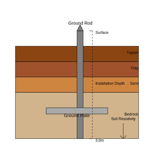
Driven ground rods are typically made of copper or galvanized steel and are characterized by their vertical installation into the ground. They are designed to provide a low-resistance path to the earth. The effectiveness of these rods in grounding is primarily influenced by several factors:
- Material: Copper is favored for its superior conductivity and resistance to corrosion.
- Length: Standard lengths range from eight to ten feet, although longer rods may be required in high-resistivity soils.
- Diameter: A larger diameter can reduce resistance; standard diameters include ¾ inch or 1 inch.
The installation process involves driving the rod into the ground using a hammer or power driver, ensuring that at least 8 feet is embedded below the surface. In scenarios where rocky soil conditions prevail, alternative techniques such as excavation or drilling holes for insertion may be required.
Calculating Ground Resistance
Ground resistance is a key parameter in evaluating grounding system effectiveness. It can generally be calculated using the following equation:
Where:
- Rg: Ground resistance (ohms).
- ρ: Soil resistivity (ohm-meters).
- L: Length of the ground rod (meters).
- d: Diameter of the ground rod (meters).
This equation illustrates that longer rods and lower soil resistivity contribute to reduced grounding resistance, enhancing the efficiency of the grounding system.
Ground Plates
Ground plates function similarly to ground rods but differ in their design and application. They are typically rectangular or square and installed horizontally underground, offering a larger surface area that can help lower ground resistance, especially in terms of contact with surrounding soil. Ground plates are particularly advantageous in regions with high soil resistivity or for applications requiring low-resistance grounding.
The installation involves burying the plate at a minimum depth, ensuring adequate soil contact. Typically, a copper or galvanized steel plate measuring 2 feet by 2 feet and at least 1/4 inch thick is used.
Resistance of Ground Plates
To determine the resistance offered by a ground plate, one can use the equation:
Where:
- Rg: Ground resistance (ohms).
- ρ: Soil resistivity (ohm-meters).
- D: Diameter of the area influenced by the plate (meters).
- d: Equivalent radius of the plate (meters).
This relationship indicates that as the diameter of the influence area around the plate increases, the resistance decreases, enhancing grounding efficiency.
Practical Applications
Driven ground rods and plates are employed in numerous practical applications. They play an essential role in:
- Electrical substations: Ensuring safe dissipation of fault currents.
- Telecommunication towers: Reducing lightning strike risks and maintaining system integrity.
- Residential and commercial buildings: Providing grounding for safety systems and electrical appliances.
In summary, understanding the principles and methodologies behind driven ground rods and plates is critical for professionals responsible for designing and maintaining reliable electrical grounding systems. Optimal grounding is paramount not only for equipment protection but also for safeguarding human life in various settings. The choice between using rods or plates often lies in evaluating the specific environmental conditions and application requirements, ensuring a tailored solution to grounding challenges.
2.4 Grounding through Building Structures
Grounding through building structures refers to utilizing the physical structure or shell of a building as an integral component of its electrical grounding system. This method is especially significant in modern architectural designs, where coupling electrical safety with structural integrity becomes increasingly crucial. The discussion of this topic necessitates a thorough understanding of the underlying principles of electrical grounding effectiveness, along with insights into practical applications and considerations.
Understanding the Concepts of Grounding
At its core, grounding is the process of establishing a connection between an electrical system and the Earth, effectively providing a common reference potential and a path for fault currents. Electrical grounding serves several primary purposes:
- Safety: It minimizes the risk of electrical shock by preventing dangerous voltage levels on exposed conductive parts.
- Equipment Protection: Grounding protects sensitive electronic equipment from surges and transient voltages.
- System Stability: It enhances the reliability of electrical systems by stabilizing voltage levels.
Incorporating Building Structures in Grounding Systems
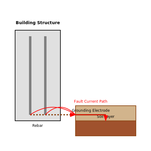
Utilizing the building structure itself for grounding can optimize the grounding system's efficiency. This involves employing materials within the structure, such as rebar in concrete or metallic frameworks, which can create a low-resistance path to the ground. The effectiveness of this grounding method depends on various factors, including:
- Material Conductivity: The choice of materials significantly affects resistance values. For instance, steel rebar has a lower resistivity compared to concrete, enhancing the grounding pathway.
- Structural Design: The design and layout of the building influence how effectively grounding components are integrated. Considerations must include how grounding connections are made to structural elements.
- Soil Conductivity: The surrounding ground conditions, such as moisture content and soil composition, impact the overall grounding effectiveness.
The Role of Rebar in Grounding
The embedded steel rebar can serve as a convenient grounding conductor. When properly configured, it can reduce ground resistance to within acceptable limits. The performance of such a grounding system can be modeled mathematically, taking into consideration the geometric arrangement of the rebar and its distance to ground level.
In this equation:
- R: Resistance of the grounding path.
- ρ: Resistivity of the material (in ohm-meters).
- L: Length of the grounding conductor (in meters).
- A: Cross-sectional area of the conductor (in square meters).
Minimizing R requires strategically placing the rebar and ensuring continuity in conductive pathways, which can also ensure structural reinforcement.
Practical Applications and Considerations
Designers and engineers often incorporate grounding through building structures in high-tech environments, such as data centers, healthcare facilities, and research labs. In these applications, the grounding system must also meet compliance with national and local electrical codes, which often require particular specifications for grounding systems to ensure public and worker safety.
Furthermore, during construction or renovations, assessing existing grounding systems becomes critical. Grounding effectiveness can be tested using various tools, including earth resistance testers, to ensure safety standards are consistently met.
The integration of ground fault monitoring systems also allows for real-time assessment of the grounding effectiveness through alerts and notifications when fault conditions arise, enhancing safety and operational reliability.
Ultimately, grounded structures not only fulfill electrical safety standards but can also enhance the durability and sustainability of building designs, providing dual benefits in safety and utility.
3. Installation and Wiring Best Practices
3.1 Installation and Wiring Best Practices
Electrical grounding and earthing are fundamental components of electrical systems, ensuring safety, performance, and equipment longevity. When it comes to the installation and wiring of ground systems, precision and adherence to best practices are paramount. This section delves into guidelines and techniques for achieving effective and compliant installation.
Understanding Grounding Systems
A grounding system is not merely a convenience; it is a critical safety measure designed to protect individuals and equipment from voltage surges, electrical faults, and lightning strikes. Grounding helps to ensure that in case of a fault, the electrical current has a safe path to the ground, which minimizes the risk of electric shock and equipment damage.
Standards and Regulations
Compliance with national and local standards, such as the National Electrical Code (NEC) in the United States, is essential when designing and installing grounding systems. These regulations provide guidelines for the materials, methods, and placement of grounding components. Familiarity with these regulations is crucial for engineers and technicians involved in electrical installations.
Materials and Components
The selection of materials for grounding systems plays a pivotal role in their effectiveness. Components typically include:
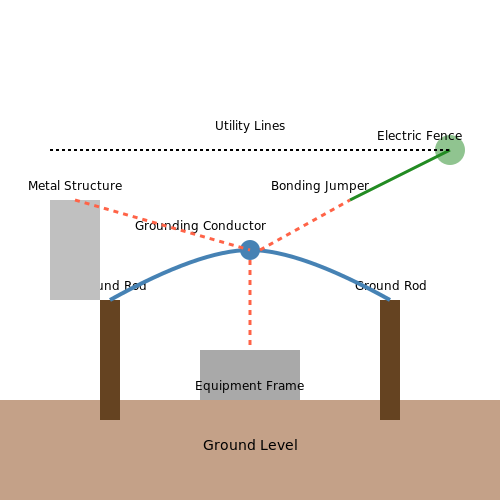
- Ground Rods: Commonly made of copper or galvanized steel, ground rods are driven into the earth and serve as the primary connection point to a grounding system.
- Grounding Conductors: These conductors connect various system parts to the ground and should be of adequate size and material that complies with NEC requirements.
- Bonding Jumpers: Used to connect non-current-carrying metal parts of equipment to ground, these ensure that any fault current is managed properly.
Best Practices for Installation
Successful grounding system installation encompasses several key practices:
1. Proper Depth and Location
The depth of ground rods should typically be at least eight feet, depending on local conditions such as soil resistivity. Locating ground rods away from electric fences, utility lines, and other potential interference is crucial to maintaining performance.
2. Correct Grounding Conductor Sizing
Grounding conductors must be sized according to the anticipated fault current. The American Wire Gauge (AWG) system provides guidelines, where larger sizes correspond to lower resistances and improved current-carrying capabilities. For instance, a typical copper grounding conductor might be sized at a minimum of #6 AWG for residential installations.
In this equation, R is the resistance of the grounding conductor, ρ is the resistivity of the material, L is the length, and A is the cross-sectional area. Calculating the resistance helps ensure that the grounding system provides an effective path for fault currents.
3. Bonding and Interconnection
All conductive elements likely to be energized must be bonded together to ensure they maintain a similar electrical potential. This includes equipment frames, metal structures, and conductive pathways. Use appropriate bonding jumpers and maintain continuity throughout the system.
4. Regular Testing and Maintenance
Periodic testing of grounding systems is essential to confirm their effectiveness. Tools such as earth resistance testers can help evaluate performance. Resistance values less than 25 ohms are generally desirable for most applications. Regular maintenance ensures that corrosion, which can compromise grounding effectiveness, is addressed promptly.
Case Studies and Real-World Applications
In several industries, ground systems have demonstrated their value:
- Telecommunications: In telecommunications facilities, well-designed grounding systems prevent equipment failures and maintain service quality during electrical storms.
- Industrial Manufacturing: In factories, grounding systems reduce downtime due to electrical issues, ensuring continuous and safe operations of machinery.
By following these best practices for installation and wiring of grounding systems, engineers and technicians can contribute significantly to safety and operational integrity in their electrical systems.
3.2 Testing and Maintenance of Grounding Systems
In the realm of electrical safety and system reliability, the testing and maintenance of grounding systems are paramount. Grounding systems, often taken for granted, play a critical role in ensuring minimal electrical hazard exposure and proper equipment functionality. The increasing complexity of electrical installations, coupled with stringent safety regulations, underscores the necessity for meticulous testing and proactive maintenance practices. To effectively manage grounding systems, it is essential to understand the various testing methods available, the standards they adhere to, and the routine maintenance practices that sustain system integrity.Ground Resistance Testing
A fundamental aspect of grounding system assessment is measuring ground resistance. This metric helps evaluate the effectiveness of the ground connection in dissipating unwanted electrical currents. The most common method employed is the fall of potential method, where the test apparatus comprises three electrodes: a current electrode, a potential electrode, and the ground itself. The measurement setup requires a known current to be passed through the ground, and using voltage measurement across the potential electrode, the resistance can be computed using Ohm's law. We can express ground resistance \( R_g \) mathematically as:Continuity Testing
Grounding systems must also maintain continuity to ensure that all grounding connections are intact. A continuity test involves verifying that the entire grounding pathway, which includes connections to grounding rods and equipment, remains electrically continuous. Testing can be performed using a simple ohmmeter. By measuring resistance across different sections of the ground path, any disconnections, corrosion, or failures can be identified. An acceptable reading is one close to zero ohms, indicating effective connectivity. Regular continuity tests should form part of a grounding system's routine checks, especially after maintenance work or in aging infrastructure.Inspection and Maintenance Practices
Beyond the technical testing, the maintenance of grounding systems requires a systematic approach:- Visual Inspections: Routine examinations should be carried out to check for physical damage, rust, or corrosion on conductive components.
- Connection Tightening: Over time, connections may loosen, allowing for increased resistance. Regular tightening should mitigate this issue.
- Electrode and Wiring Condition: The physical state of the ground rods, wires, and bonding should be monitored for degradation.
- Documenting Findings: Maintaining records of all tests, measurements, and inspections helps track system performance and plan future maintenance activities.
Conclusion
In conclusion, effective testing and maintenance of grounding systems are essential for ensuring electrical safety and system reliability. By regularly measuring ground resistance, assessing continuity, and promptly executing maintenance protocols, engineers and technicians can significantly enhance the operational stability of electrical installations. Research and historical case studies have shown that neglecting these practices can lead to severe accidents and equipment failures. Therefore, incorporating rigorous testing and keen maintenance into standard operating procedures should be a fundamental aspect of any electrical system management strategy. Overall, understanding the intricacies of grounding systems, combined with steadfast testing and maintenance practices, will foster not only compliance with regulatory standards but also enhanced safety and performance in electrical systems.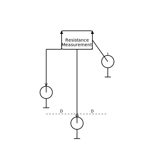
3.3 Common Grounding Mistakes and How to Avoid Them
In the realm of electrical grounding and earthing, precision is paramount. Though the principles of grounding are well established, numerous stumbling blocks can arise from misunderstandings or misapplications of these principles. This section sheds light on several common grounding mistakes and provides strategies to circumvent these pitfalls.Improper Grounding Techniques
One of the most prevalent mistakes involves the use of improper grounding techniques. Engineers sometimes fail to recognize the distinction between grounding for safety and grounding for system performance. While touching on safety, grounding methods should also consider electromagnetic compatibility (EMC) and interference suppression, particularly in sensitive electronic environments. To ensure effective grounding, consider these key aspects:- Single-point grounding: Using a centralized grounding point avoids ground loops that can introduce noise and electromagnetic interference.
- Minimum ground resistance: Grounding systems should be evaluated using methods like the fall-of-potential test to ensure resistance values remain low, ideally below 5 ohms for general applications.
- Correct conductor sizing: The ground conductor must adequately handle fault currents without melting or breaking. This consideration is often dictated by standards such as the National Electrical Code (NEC).
Neglecting Grounding Maintenance
Another frequent error stems from inadequate maintenance of grounding systems. Over time, environmental factors—such as corrosion, soil degradation, or physical disturbances—can impair grounding effectiveness. Failure to inspect and maintain grounding systems can result in increased impedance and, consequently, hazardous conditions. Effective maintenance guidelines include:- Regular inspections: Schedule periodic assessments of grounding systems to identify wear, corrosion, or physical damage. Early detection can prevent system failures.
- Testing and documentation: Use measurement techniques such as ground resistance testing and ensure results are systematically documented for future reference.
- Adjustments based on environmental changes: Adapt the grounding solution as the environmental or building conditions evolve to ensure continued reliability.
Overlooking Local Codes and Standards
Compliance with local regulations is frequently overlooked, leading to grounding systems that are legally and functionally inadequate. Local electrical codes (such as NEC in the United States) dictate grounding practices tailored to regional safety hazards. Key strategies for complying with regulations include:- Familiarization with local codes: Each jurisdiction has unique requirements concerning grounding systems. Understanding these requirements is critical for meeting legal and safety standards.
- Professional consultations: Engaging with certified electrical engineers or consultants can ensure compliance and best practices are upheld.
- Documentation and permits: Maintaining proper records, including permits and inspection reports, is vital for legal obligations and quality assurance.
Ignoring External Influences on Grounding
Lastly, many professionals neglect the impact of external factors, such as load changes or nearby structures, on grounding effectiveness. Variations in load can change ground potential, leading to safety hazards. To address this issue, consider:- Monitoring load changes: Continuous evaluation of electrical loads can help identify when recalibration or redesign of the grounding system is necessary.
- Assessing nearby structures: Proximity to large conductive structures or systems can affect grounding performance through induced currents. Understanding these impacts is essential.
- Adaptation to operational changes: Continuous system evaluation should accompany any renovations or expansions that could impact grounding conditions.
4. Comparison Between Grounding and Earthing
4.1 Comparison Between Grounding and Earthing
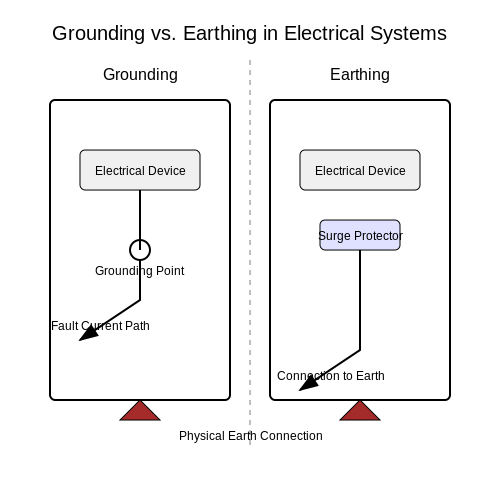
The terms "grounding" and "earthing" are often used interchangeably, yet they encapsulate distinct concepts, especially in the contexts of engineering and physics. Understanding the nuanced differences can be pivotal for advanced practitioners involved in design, implementation, and safety within electrical systems.
Definitions and Contexts
Grounding typically refers to the connection of electrical circuits to the ground or a conductive body that serves as a ground reference for electric power systems. This practice is crucial for ensuring safety and device protection, as it provides a defined path for fault currents, reducing the risk of electric shock and equipment damage.
Conversely, earthing is a term commonly used in European and other international standards, largely rooted in a broader physical philosophy. While it can also imply a connection to the earth, in certain contexts, it specifically relates to grounding systems designed primarily for safety. In many regions, earthing may also refer to the physical earth connection itself rather than just the grounding system.
Key Differences
- Functionality: Grounding primarily concerns the operational safety of electrical devices, ensuring they function within safe limits, while earthing often emphasizes the safety aspect by anchoring systems to the physical earth.
- Standards and Norms: Different regions may employ different standards. For instance, in the United States, the National Electrical Code (NEC) emphasizes grounding methodologies, while the International Electrotechnical Commission (IEC) promotes earthing practices.
- Implementation: Grounding systems might include various configurations like single-point or multi-point systems to address the specific needs of electrical distribution. In contrast, earthing systems may involve additional protective devices such as surge protectors to manage atmospheric disturbances.
Practical Implications
In practice, the implications of grounding and earthing are profound. For instance, in advanced electrical installations — such as data centers or critical infrastructure — the distinction becomes vital. A well-implemented grounding system may mitigate electromagnetic interference, while an effective earthing system could safeguard against surges due to lightning strikes.
Case Studies and Real-World Applications
One striking example is in telecommunication systems, where grounding is essential for maintaining signal integrity, while earthing protects sensitive equipment from voltage spikes. In such applications, engineers must carefully design both systems to coalesce, ensuring not only the functionality of electronic systems but also the safety of personnel and equipment.
In summation, while grounding and earthing may serve similar overarching purposes in electrical systems, recognizing their intricacies and practical applications allows engineers and physicists to design safer, more reliable electrical infrastructures. By understanding these differences, professionals can tailor their systems more effectively, enhancing resilience against electrical faults and environmental factors.
4.2 Earthing Systems in Power Distribution
Electrical grounding, commonly known as earthing, is pivotal in the realm of power distribution, providing a safe pathway for electrical currents, particularly in fault conditions. Understanding the various earthing systems in use is essential for engineers and technologists involved in power system design, installation, and maintenance.
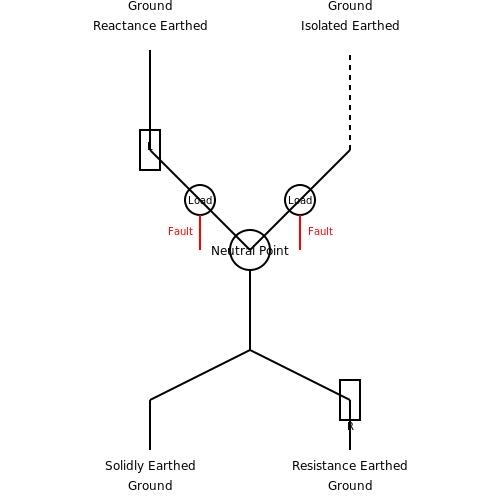
In power distribution systems, earthing methods can fall under several categories, primarily defined by their connection structures to the earth and their operational characteristics. The most prevalent earthing systems include:
- Direct Earthing (Solidly Earthed Systems): This system connects the neutral point of the transformer directly to the ground. Solidly earthed systems minimize transient over-voltages and improve the stability of the system, making them suitable for low-voltage distribution systems.
- Resistance Earthing: In resistance earthing, a resistor is connected between the neutral point and the earth. This configuration limits the fault current during an earth fault to a predetermined value, thereby reducing the risk of equipment damage while allowing for fault detection and isolation.
- Reactance Earthing: This system uses an inductor or reactance device in series between the neutral and earth. It serves to control the earth fault currents while offering a smoother response to ground faults compared to solidly earthed systems.
- Isolated Earthing: Here, the neutral point is isolated from the earth, creating a system where no intentional earthing exists. This approach reduces the risk of earth faults in sensitive equipment, making it ideal for industrial applications where equipment sensitivity is paramount.
Understanding Load Characteristics in Earthing Systems
To effectively choose the right earthing system, one must understand the electrical load characteristics and the electrical environment of the installation. For instance, the ease of fault current detection in a resistively earthed system enables prompt isolation of faulted equipment, contributing to safety and reliability in operations. The time to clear faults and the magnitude of fault currents are critical parameters influenced by the type of earthing employed. Additionally, various load conditions like unbalanced loads can alter the behavior of different systems.
Practical Applications and Case Studies
In practical applications, the choice of earthing system is often guided by regulatory standards and the specific requirements of the power distribution network. For example, industries that operate sensitive electronic equipment, such as semiconductor manufacturing, often adopt isolated earthing to prevent inadvertent damage from ground faults.
Consider a case study in a metropolitan power distribution network. The adoption of a solidly earthed system allowed for rapid fault detection and clearing, significantly improving service availability. Meanwhile, in a large-scale renewable energy project, resistance earthing was chosen to mitigate the risks during fluctuating generation conditions and varying load demands. Such real-world implementations demonstrate the importance of selecting an appropriate earthing system tailored to the specific operational context.
Conclusion
The design and selection of earthing systems in power distribution is a critical engineering task. It shapes the safety, reliability, and efficiency of the electrical infrastructure. Knowledge of different earthing systems enables engineers to make informed decisions that are crucial for the functionality of power distribution networks, directly influencing both operational integrity and regulatory compliance.
4.3 Earthing for Equipment Protection
The importance of earthing, or grounding, in electrical systems cannot be overstated, particularly when it comes to protecting equipment from damage that can result from electrical faults. When considering the safeguarding of sensitive electronic equipment, the approach to earthing becomes critical both for functional integrity and safety. This section delves into the methodologies, significance, and practical applications of earthing as a protective measure.The Mechanism of Earthing
Earthing serves as a crucial path for fault currents, directing high currents safely to the ground to prevent damage to equipment and reduce the risk of electric shock. By establishing a low-resistance connection to the earth, excess electrical charge can be discharged. This principle is critical for protecting sensitive devices such as computer systems, communication equipment, and automated machinery. The performance of earthing systems is defined by their resistance to ground, which is influenced by factors such as soil resistivity, moisture content, and the physical configuration of the grounding conductors. To ensure effective earthing, it is fundamental to minimize the resistance through careful material selection, depth of grounding rods, and layout of grounding grid systems.Technical Standards and Methods
Various standards, such as the IEEE 80 and the IEC 60364, provide comprehensive guidelines on earthing systems for equipment protection. Key considerations include:- Low Resistance Grounding: A grounding system should aim for a resistance value below 5 ohms. This is essential for high-current systems where quick response to faults is necessary.
- Bonding Conductors: All exposed conductive parts must be bonded together and connected to the ground to prevent potential differences that could lead to electrocution or equipment failure.
- Grounding Electrode System: The electrode system should consist of rods, plates, or a grid that provides a low-resistance pathway to the earth. Consideration should also be given to supplemental grounding mechanisms such as ground rings and mesh.
Mathematical Consideration of Ground Resistance
The resistance of a grounding electrode can be approximated using the formula:- R is the resistance in ohms (Ω)
- K is a constant that depends on the electrode configuration
- ρ is the resistivity of the soil in ohm-meters (Ω·m)
- L is the length of the electrode in meters (m)
Applications in Industry
In practice, the principles of earthing extend across multiple industries. Data centers, for example, utilize sophisticated earthing systems to protect servers from transient surges caused by lightning strikes or switching operations. The grounding systems not only safeguard the hardware but also ensure reliable data transmission, thus preventing financial losses associated with downtime. Healthcare facilities demand even stricter grounding protocols due to the sensitive nature of medical equipment. The importance of grounded equipment in operating rooms and diagnostic rooms is paramount to the avoidance of electrical hazards, which could jeopardize patient safety.Conclusion
As seen, the act of implementing a robust earthing system transcends mere compliance with electrical codes; it is an essential strategy that safeguards both human lives and vital equipment from electrical faults. An awareness of the ground resistance and robust bonding methods also assures both performance and safety, particularly in advanced applications where electrical reliability is non-negotiable. As technology continues to evolve, innovations in grounding practices will further enhance the resilience of electrical systems against faults and surges.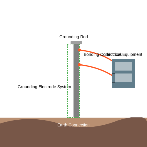
5. National Electrical Code (NEC) Guidelines
5.1 National Electrical Code (NEC) Guidelines
The National Electrical Code (NEC), developed by the National Fire Protection Association (NFPA), serves as a benchmark for electrical safety in the United States. It establishes regulations to minimize the risk of electrical hazards, ensuring that electrical installations are both efficient and safe. Understanding NEC guidelines for electrical grounding and earthing is crucial for engineers and professionals in the field, as adherence to these standards not only complies with legal mandates but also enhances the reliability of electrical systems.
Grounding and earthing are integral components in electrical systems, aimed at protecting both people and equipment. The NEC classifies grounding systems into several categories, each serving specific functions ranging from safety to equipment protection. Among these, the following aspects warrant careful consideration:
Definition of Grounding and Earthing
Grounding refers to establishing a direct electrical connection to the earth or to a conductive body that serves in place of the earth. Conversely, earthing is more focused on the connection of electrical systems to the ground, which is critical in protecting personnel from electric shock and preventing fault currents from damaging equipment. Aside from safety, proper grounding reduces electromagnetic interference, enhancing the operational integrity of electrical systems.
NEC Articles on Grounding and Earthing
The NEC encompasses several articles pertinent to grounding and earthing, such as:
- Article 250: Grounding and Bonding - This article covers the requirements for grounding systems, including the installation of grounding electrodes, the size of grounding conductors, and the necessary bonding connectors.
- Article 300: Wiring Methods - This section describes acceptable wiring methods and techniques that directly impact the effectiveness of grounding systems.
- Article 800: Communications Circuits - This provides guidelines about the grounding of communication lines, recognizing their significance in overall system reliability.
Grounding Electrode Systems
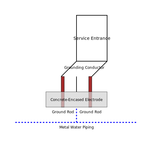
According to NEC guidelines, a grounding electrode system should be installed as close as practicable to the electrical service entrance, with a minimum number of electrodes required depending on the installation type. The NEC specifies multiple grounding electrode conductors, with copper and aluminum being common materials. In this context, it is essential to use the correct sizing of grounding conductors as defined by NEC Table 250.66, taking into account the size of the largest service-entrance conductors. This ensures the selected grounding system can safely carry fault currents without degradation.
For effective grounding electrode systems, the NEC outlines a range of installation types:
- Ground rods: Copper or galvanized steel rods driven into the earth.
- Metal underground water piping: Must be bonded if used as a grounding method.
- Concrete-encased electrodes: Such as a reinforcing bar in concrete foundations.
Real-World Applications and Implications
In practice, compliance with NEC guidelines enhances safety in residential and commercial electrical systems. A significant case is observed in refineries and industrial plants where proper grounding systems prevent catastrophic failures owing to stray currents. By following NEC guidelines, engineers can mitigate electrical shock hazards while enhancing system stability and equipment lifespan.
Furthermore, as we advance into a world increasingly reliant on technology and integrated circuits, grounding methods must adapt accordingly to evolving standards, including considerations for electromagnetically sensitive equipment. Keeping abreast of NEC updates ensures that professionals can implement effective and compliant grounding systems that address contemporary demands.
5.2 International Electrotechnical Commission (IEC) Standards
The International Electrotechnical Commission (IEC) plays a pivotal role in the establishment of safety and performance standards in electrical systems worldwide. Among its extensive range of publications, IEC standards provide essential guidelines that profoundly influence electrical grounding and earthing practices. Understanding these standards is crucial for engineers, physicists, and researchers seeking to ensure safety, reliability, and compliance in electrical installations.Significance of IEC Standards in Grounding and Earthing
The fundamental purpose of grounding and earthing is to provide a safe path for electric current in case of faults, as well as to stabilize voltage levels in electrical systems. The IEC has developed several specific standards that address various aspects of grounding and earthing mechanisms. Compliance with these standards not only meets regulatory requirements but also enhances operational efficiency and safety.Key IEC Standards Relevant to Grounding
Several IEC standards interrelate with grounding and earthing practices, with the most notable being:- IEC 60364: This standard outlines the low-voltage electrical installations requirements, providing guidance on proper grounding techniques to ensure safety and functionality. Each section addresses different aspects of electrical systems, from installation to maintenance.
- IEC 61000-5-2: This standard focuses on electromagnetic compatibility (EMC), prescribing requirements for earthing and bonding, essential for reducing the effects of electromagnetic interference (EMI) in electrical environments.
- IEC 61557: This standard defines the requirements for electrical safety in systems for measuring the effectiveness of earthing. It sets forth performance criteria necessary for the evaluation of earthing impedance.
Practical Implications and Applications
In a real-world context, adherence to IEC standards has beneficial implications across various industries: - In Electrical Utilities: Utilities often use IEC standards to design grounding systems that can dissipate lightning strikes or electrical faults effectively, protecting personnel and equipment. - In Industrial Settings: Factories implement IEC guidelines to create robust earthing systems that reduce the risk of equipment malfunctions due to electrical surges, thereby optimizing productivity. - In Commercial Buildings: Architects and engineers reference IEC standards when designing buildings to ensure that earthing methods comply with best practices, facilitating the safe operation of electronic systems. Through rigorous adherence to these standards, organizations can significantly mitigate risks associated with electrical failures.Conclusion
As electrical systems continue to evolve, the importance of compliance with IEC standards remains paramount. These documents provide critical frameworks for designing grounding and earthing systems that not only ensure safety but also enhance system reliability. For advanced practitioners in the field, a thorough understanding of IEC standards is essential for innovating solutions that adhere to global safety benchmarks. For further inquiries or in-depth exploration of specific IEC standards, the following resources can serve as an important guide.- International Electrotechnical Commission (IEC) Official Site — Access comprehensive information about IEC standards, publications, and ongoing projects in electrotechnical standardization.
- IEEE Standards Association — Explore a range of documents addressing electrical safety and grounding standards relevant to various industries.
- National Fire Protection Association (NFPA) — Review guidelines on fire safety that include grounding practices for minimizing fire hazards in electrical installations.
- National Electrical Manufacturers Association (NEMA) — Find standards that address grounding requirements in the domestic and industrial application of electrical systems.
- International Organization for Standardization (ISO) — Learn about collaborative international standards that complement IEC's efforts in electrical safety and grounding.
- Electrical Engineering Portal — A resource offering detailed articles and tutorials on grounding and earthing techniques as per IEC standards, including practical insights.
- Cascade Energy — An informative site dedicated to the impact of effective grounding methods on energy conservation and electrical safety.
5.3 Local Regulations and Compliance
Understanding the nuances of electrical grounding and earthing becomes increasingly vital when we delve into the realm of local regulations and compliance. The necessity for adherence to these directives cannot be overstated, as they exist to protect both personnel and equipment while ensuring the safety and reliability of electrical systems. Local regulations often encompass various codes, standards, and legal requirements specific to electrical installations, which can vary not only by country but also by regions within a country.
The Role of Local Codes
Local building codes, including the National Electrical Code (NEC) in the United States or the IET Wiring Regulations (BS 7671) in the UK, outline the fundamental requirements for electrical installations, including grounding and earthing practices. These codes are designed based on rigorous research and case studies, including historical data of electrical incidents and failures. Compliance with these codes is often legally mandated, serving to minimize hazards and ensure consistency across the industry.
An essential element to appreciate is that these codes often evolve. They undergo regular updates to incorporate advancements in technology and findings from tragedies that redefine best practices in electrical safety. For instance, recent amendments in the NEC have addressed issues such as the increased use of renewable energy sources and electric vehicle charging stations, which introduces new grounding requirements.
National vs. International Standards
While local codes focus on specific geographical practices, international standards, such as those set by the International Electrotechnical Commission (IEC), provide guidelines that can be beneficial for engineers working on multinational projects. Understanding the intersection of local and international standards can assist in ensuring full compliance while also adhering to best practices globally.
- Knowledge Application: Engineers should apply knowledge of local codes when designing systems, ensuring that grounding practices are not only robust but also compliant. This knowledge can be operationalized through careful planning and consultation during the project design phase.
- Documentation: Compliance often requires meticulous documentation of the grounding systems applied, including test results and installation methods. Such documentation is crucial during inspections and can provide a defense in case of future liabilities.
Practical Compliance Challenges
In practice, issues may arise during projects that inadvertently lead to non-compliance. For instance, a misinterpretation of local codes might result in inadequate grounding systems that fail to meet safety requirements. Such oversights can have catastrophic consequences, potentially resulting in electrical fires or damage to sensitive equipment.
To mitigate risks associated with non-compliance, a collaborative approach is required. Engaging with local authorities or electrical safety organizations during the design and installation phases helps ensure that all regulations are adhered to properly. Regular audits and reviews of existing systems should also be conducted to align with ongoing changes in legislation.
Conclusion
Ultimately, abiding by local regulations and compliance standards is not merely a legal obligation; it is a fundamental aspect of practicing electrical engineering responsibly. Understanding the layered requirements—from local codes to international standards—empowers professionals to make informed decisions that enhance safety and system performance in both existing and new facilities.
As technologies evolve, so too should our practices, ensuring that electrical grounding and earthing principles remain at the forefront of safety strategies within our electrical systems.
6. Identifying Ground Faults
6.1 Identifying Ground Faults
Identifying ground faults is a critical aspect of ensuring electrical safety and system reliability. A ground fault occurs when there is an unintended path between an electrical system and the earth or between conducting surfaces. This can pose risks like electrical shock, equipment damage, and fire hazards. Understanding how to identify ground faults helps engineers and technicians to maintain safe and efficient systems.Understanding Ground Faults
Ground faults typically manifest when insulation fails, moisture infiltrates equipment, or physical damage occurs to electrical conductors. Each of these scenarios creates a low-resistance path for current to flow to the ground unexpectedly. Ground faults can be particularly dangerous in moist environments or in circuits where sensitive equipment is deployed, such as in medical facilities. Ground faults can be categorized into two main types: earth faults and ground faults. An earth fault occurs when a live conductor makes contact with the ground, while a ground fault involves contact with an exposed conductive surface. In practice, both can be detected using various methods.Techniques for Identifying Ground Faults
There are several methods for identifying ground faults, each with its unique principles and applications:- Visual Inspection: This initial step involves checking for visible signs of damage such as frayed wires, burnt insulation, or moisture accumulation.
- Insulation Resistance Testing: By applying a voltage (usually 500 V or more), insulation resistance testers measure the resistance between live conductors and ground. Low resistance levels indicate potential faults.
- Ground Fault Circuit Interrupters (GFCIs): These devices continuously monitor the current flowing to and from electrical equipment. A disparity in this flow can trigger the interrupter to disconnect power, indicating a ground fault.
- Current Leakage Measurement: Using clamp-on ammeters, technicians can measure leakage currents that can signify unintentional paths to the ground.
- Time Domain Reflectometry (TDR): This advanced technique sends a pulse down a cable and analyzes reflections to detect faults along the circuit. It is particularly effective for underground or protected cables.
The Role of Modeling Ground Faults
Understanding the behavior of electrical systems under fault conditions is enhanced by modeling. Engineers can simulate various fault scenarios using software tools to predict the effects of ground faults on system stability and performance. This predictive capability supports the design of more resilient electrical systems. Mathematically, ground faults can be analyzed using circuit theory. Ohm’s Law can help in quantifying fault currents when a fault condition occurs. For instance, if we assume a ground fault can be modeled as a resistance \( R_f \), the current \( I_f \) through the fault can be expressed as:Practical Applications and Standards
Effective identification of ground faults is crucial not just for safety, but also for compliance with various standards such as the National Electrical Code (NEC) and the International Electrotechnical Commission (IEC) standards. Compliance ensures that systems are designed and maintained to minimize the risk of electrical hazards. In the industrial setting, the integration of ground fault detection systems can greatly reduce downtime caused by equipment failure. For example, motors are often equipped with ground fault sensors that can automatically shut them down, preventing extensive damage and costly repairs. This proactive approach illustrates how modern technology is employed in tandem with traditional identification methods to enhance electrical safety. In conclusion, identifying ground faults is an essential skill for engineers and technicians working with electrical systems. By employing a combination of visual inspections, testing methods, and advanced modeling techniques, professionals can safeguard both people and equipment from the dangers posed by ground faults.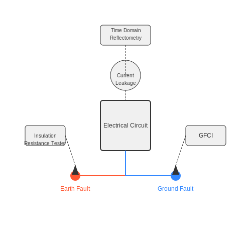
6.2 Measuring Ground Resistance
Measuring the resistance of an electrical ground system is critical in ensuring the reliability and functionality of electrical installations. Ground resistance should ideally be kept low to allow fault currents to safely dissipate into the earth, thereby minimizing electrical shock hazards and equipment damage. This section will delve into techniques and methodologies to accurately measure ground resistance, the implications of these measurements, and their relevance in practical applications.Understanding Ground Resistance
Ground resistance is defined as the resistance encountered by an electrical current when it travels from the grounding system into the ground. This value is critical because high ground resistance can lead to inadequate fault protection. It is essential, especially in systems with sensitive electronic equipment, where grounding plays a significant role in electromagnetic interference (EMI) mitigation. To understand ground resistance towards measurements, we need to consider the grounding electrode system, which usually comprises rods, plates, or other conductive materials installed in the earth. The resistance can heavily depend on several factors, including soil resistivity, moisture content, temperature, and the depth at which the electrodes are installed. The equation that typically represents the relationship between these variables is given by: $$ R_g = \frac{\rho}{A} $$ where \( R_g \) is the ground resistance, \( \rho \) is the soil resistivity (dependent on moisture content and material), and \( A \) is the area of the ground electrode.Methods of Measuring Ground Resistance
There are several methods available for measuring ground resistance, each suitable for different applications and environments. The most commonly used methods include:- Four-Point Probe Method: This method employs four stakes driven into the ground. Current is passed between two of the stakes, and voltage is measured across the outer two. The resistance can be calculated using Ohm's Law.
- Fall-of-Potential Method: This methodology utilizes a single electrode and involves measuring the resistance by determining the potential of the ground at various distances from the electrode. A voltage gradient is established, and resistance values are extrapolated.
- Soil Resistivity Test: Soil resistivity testing is often conducted prior to installing a grounding system. This method evaluates the soil's behavior under different moisture and temperature conditions, giving insight into potential ground resistance problems.
Using the Fall-of-Potential Method
The Fall-of-Potential method is intricate and highly reliable. It involves the following steps: 1. Place a grounding electrode in the ground. 2. Connect a current source to the electrode and pass a current through it. 3. Measure the voltage drop from the electrode as it is moved away from the probable point of the earth return path. 4. Calculate the resistance using the following formula:Practical Relevance
Monitoring and maintaining low ground resistance is significant for both safety and operational efficiency. In power plants, substations, and data centers, consistent ground resistance tests prevent unexpected electrical failures. For instance, in the event of a fault, a low ground resistance facilitates the prompt dissipation of current through the earth, thus enhancing personnel safety. Furthermore, monitoring ground resistance over time allows engineers to detect changes in soil conditions or potential corrosion of grounding electrodes, ensuring preemptive actions can be taken to maintain compliance with safety standards and regulations. In summary, understanding and measuring ground resistance is paramount in both theoretical studies and practical applications. As we move forward, we will explore regulatory standards and guidelines essential for grounding systems to be deemed effective in their applications.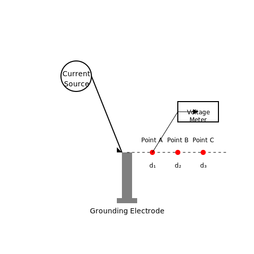
6.3 Solutions for Poor Grounding
Electrical grounding and earthing are critical for the safety and functionality of electrical systems. When grounding is inadequate, various complex issues arise, such as electrical shock hazards, equipment failures, and electromagnetic interference. This section delves into robust solutions to mitigate the problems associated with poor grounding.
Understanding the Underlying Causes
Before addressing solutions for poor grounding, it is essential to understand the potential causes. Common issues include:
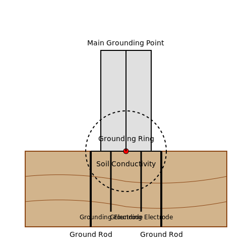
- High Ground Resistance: This can stem from poor soil conductivity, which affects the effectiveness of grounding systems.
- Corroded Connections: Connections may degrade due to environmental exposure, reducing grounding reliability.
- Improper Grounding System Design: Inadequately designed systems may not comply with standards, resulting in inefficiencies.
Recognizing these factors allows for targeted interventions in grounding systems.
Strategies for Enhancement
To rectify poor grounding, several strategies can be employed:
1. Ground Resistance Reduction
Reducing ground resistance is pivotal for an effective grounding system. It can be achieved by:
- Installing Ground Rods: Use multiple shallow-driven ground rods spaced adequately to ensure proper grounding. This complements the main grounding electrode system.
- Improving Soil Conductivity: Techniques such as adding conductive materials (e.g., sodium-based compounds) to the soil can enhance conductivity.
2. Reinforcement of Connections
Strengthening connections improves the reliability of grounding systems. Recommended practices include:
- Using Oxide-Free Connections: Employ connectors that minimize oxidation, thereby preventing resistance increases over time.
- Regular Maintenance: Conduct periodic inspections to identify and rectify corrosion or connection degradation.
3. Advanced Grounding Techniques
For specialized applications, advanced grounding techniques can be more effective. These include:
- Multiple Grounding Electrodes: Using a combination of ground electrodes (e.g., plates, rods, or mesh) can optimize the dispersion of ground currents.
- Utilizing Grounding Rings: Installing a grounding ring around structures can provide a low-resistance path to ground, particularly in conductive environments.
The implementation of multiple grounding types should correlate with local code requirements and specific system needs.
4. Electrical Isolation Techniques
Implementing electrical isolation methods can help mitigate the risks posed by poor grounding. Techniques include:
- Fiber Optics for Signal Transmission: Utilizing fiber optic cables for sensitive signal transmission avoids grounding issues associated with metallic conductors.
- Isolation Transformers: Employing isolation transformers can effectively mitigate high-frequency noise and ground loop issues, enhancing equipment performance.
Conclusion
Addressing poor grounding requires a multifaceted approach that encompasses reducing ground resistance, reinforcing connections, and employing advanced techniques. In doing so, engineers not only improve system performance but also enhance safety measures against potential electrical hazards.
7. Recommended Books on Grounding
7.1 Recommended Books on Grounding
- Earthing: The Most Important Health Discovery Ever? — This book provides an in-depth look at the concept of earthing and its health benefits. It explores the science behind grounding, presenting practical advice on how to incorporate grounding into daily life.
- Grounding and Shielding: Circuits and Interference — A comprehensive guide that delves into the theory and practice of grounding and shielding. It provides detailed methodologies for detecting and parrying interference in electrical circuits.
- Grounding Electrical Installations — This detailed guide discusses advanced techniques in grounding electrical systems, equipping engineers and electricians with the knowledge to improve system reliability and safety.
- Industrial Electricity — This book includes a section on grounding and bonding, essential for understanding the broader context of circuit integrity in industrial applications. The content is tailored for practical implementation in engineering environments.
- Lightning Protection & Grounding: A Technical Guide — It provides insights into lightning-induced issues in installations and offers strategies for grounding. This technical guide is invaluable for professionals dealing with outdoor installations prone to lightning strikes.
- Grounding with Electromagnetic Pathways — Explores the electromagnetic pathways in grounding systems with a focus on prevention and mitigation of electromagnetic interference. This book uses simulation and real-world examples for practical learning.
- NFPA 70: National Electrical Code (NEC) — While not a traditional book, the NEC is an essential reference for any electrical engineer or electrician, outlining the regulations and standards for grounding systems in electrical installations.
7.2 Relevant Research Papers and Articles
- Grounding and Earthing in Electrical Circuits - IEEE — This paper published by IEEE explores different methods of grounding and earthing in electrical systems. It provides in-depth analysis and comparative performance studies of various grounding techniques.
- Review of Grounding and Earthing Practices for Electrical Safety — This journal article examines the safety implications of various grounding and earthing practices and their impact on reducing electrical hazards.
- Advanced Earthing Techniques and Innovations — An article available on IEEE Xplore discussing the latest innovations in earthing techniques, their benefits, and implementation challenges in modern electrical systems.
- The Role of Grounding in Renewable Energy Systems — This research paper explores the critical role that grounding plays within renewable energy systems, focusing on photovoltaic and wind energy installations.
- Grounding Systems in Smart Grids: Design and Performance — This article provides insights into the design considerations and performance evaluations of grounding systems within smart grid networks.
- Novel Grounding Solutions for Aerospace Applications — Explore the challenges and solutions of grounding in aerospace engineering contexts, incorporating both electrical and mechanical considerations.
- Electromagnetic Interference and Grounding: A Materials-based Approach — A study on how different materials can enhance grounding efficiency and reduce electromagnetic interference in electronic devices.
7.3 Online Resources and Courses
- Power System Grounding by Coursera — A comprehensive course that delves into the principles and practical applications of grounding in power systems. The course includes video lectures, quizzes, and hands-on projects relevant for advanced learners.
- Introduction to Electrical Engineering by edX — Though not exclusively about grounding, this course offers modules covering essential grounding techniques as part of a broader curriculum. Ideal for engineers looking to reinforce foundational knowledge.
- Electrical Grounding Training on Udemy — Focused specifically on grounding, this course provides an in-depth exploration of topics such as grounding theory, safety standards, and real-world case studies in electrical installation.
- Electrical Equipment and Safety with Grounding by NPTEL — This free course, offered by the Indian Institute of Technology, covers grounding extensively, linking it to the broader context of electrical equipment safety.
- Khan Academy: Electrical Engineering — While covering a broad range of topics, Khan Academy's electrical engineering resources include segments pertinent to safe and effective grounding practices, supplemented by interactive exercises.
- Grounding and Bonding Course — This provider offers an advanced immersion into grounding and bonding, targeted at professionals seeking to enhance practical skills in electrical safety and system design.
- MIT OpenCourseWare: Electrical Circuit Theory — Featuring a rich repository of materials, this course includes sections on network theory and components related to grounding that are crucial for a deep understanding.
- Lynda Electronics Training — Offers a blend of video tutorials, quizzes, and projects with focused sessions on grounding in electronic systems, aimed at experienced engineers and technologists.