Fuses and Circuit Breakers
1. Purpose and Importance in Electrical Systems
Purpose and Importance in Electrical Systems
Fuses and circuit breakers serve as critical protective devices in electrical systems, designed to interrupt excessive current flow and prevent damage to equipment, wiring, and personnel. Their operation is governed by fundamental principles of electromagnetism and thermal dynamics, ensuring reliable fault isolation while maintaining system integrity.
Fundamental Operating Principles
Fuses operate based on Joule heating, where current exceeding a rated threshold generates sufficient thermal energy to melt a fusible element. The time-current characteristic follows:
Here, I represents current, t is melting time, and k is a constant determined by material properties. For a fuse with a 10A rating and k = 1000 A²s, a 20A overload would clear in:
Circuit breakers employ electromechanical tripping mechanisms. Magnetic trip elements respond instantaneously to short-circuit currents (typically 5-10x rated current), while thermal elements use bimetallic strips for delayed tripping under sustained overloads.
Key Performance Metrics
- Breaking capacity: Maximum interruptible current without arcing failure (100kA for industrial breakers)
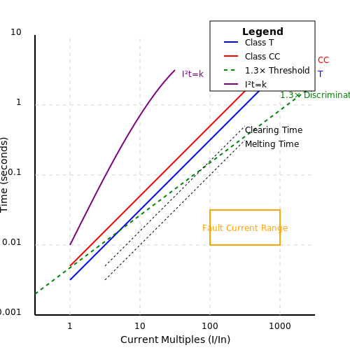
- Time-current curves: Class T (fast-acting) vs Class CC (time-delay) characteristics
- Voltage rating: Must exceed system nominal voltage (600V AC/DC for most power applications)
System Protection Coordination
Selective coordination requires careful matching of device characteristics. The discrimination ratio between upstream and downstream devices must satisfy:
Modern solid-state trip units implement programmable curves (I²t, long/short delay) for precise coordination in complex distribution networks.
Practical Design Considerations
Arc interruption presents significant engineering challenges. Current-zero quenching in circuit breakers requires:
- Vacuum interrupters (10⁻6 torr) for medium voltage
- SF₆ gas (dielectric strength 3x air) for high voltage
- Arc chutes with deion plates for low voltage molded-case breakers
Fuse materials evolve with nanotechnology - silver nanoparticle coatings reduce pre-arcing time by 40% compared to traditional zinc elements.
Standards and Compliance
Critical standards include:
- IEC 60269 (fuse characteristics)
- UL 489 (circuit breaker testing)
- IEEE C37.13 (medium-voltage switchgear)
Compliance ensures proper interrupting ratings and verifies withstand capabilities through standardized testing regimes (e.g., 30-cycle short-circuit tests).
Key Differences Between Fuses and Circuit Breakers
Operational Mechanism
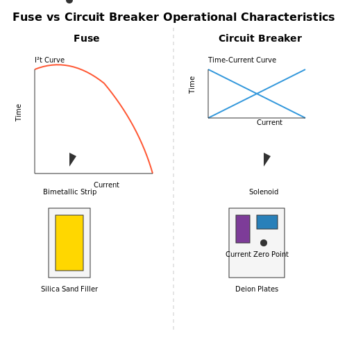
Fuses operate on the principle of thermal or electromagnetic melting. When current exceeds the rated value, the fusible element heats up and melts, breaking the circuit. The melting time t follows the I²t characteristic:
where K is a material constant, I is the current, and A is the cross-sectional area. In contrast, circuit breakers use electromechanical tripping mechanisms—either thermal (bimetallic strip) or magnetic (solenoid) actuation—to open contacts without destruction.
Reset Capability
Fuses are single-use devices; after operation, they must be replaced. Circuit breakers can be reset manually or automatically, making them reusable. This difference is critical in applications where downtime must be minimized, such as industrial power distribution or aerospace systems.
Response Time
Fuses typically respond faster to overcurrents (sub-millisecond for high-speed types) due to their passive nature. Circuit breakers have inherent mechanical delays, usually in the 10–100 ms range. The time-current curves for each follow distinct profiles:
Voltage and Current Ratings
Modern fuses support up to 600 kV and 100 kA interrupting capacity (e.g., expulsion-type HV fuses). Circuit breakers max out around 800 kV (GIS designs) but offer more precise current limiting. The let-through energy I²t is generally lower for current-limiting fuses compared to breakers.
Cost and Maintenance
Fuses have lower upfront costs but higher lifetime expenses in frequently faulted circuits. Breakers require periodic mechanical testing (per IEEE C37.09) but avoid replacement costs. High-voltage systems often use hybrid approaches—fuses for fault protection backed by breakers for switching.
Arc Quenching Methods
Fuses rely on filler material (silica sand) to absorb arc energy through granular restriction. Circuit breakers use various techniques:
- Air-break: Arc chutes with deion plates
- Vacuum: Dielectric recovery at current zero
- SF6: Electronegative gas quenching
Selective Coordination
Breakers enable precise coordination through adjustable trip settings (Ir, Isd, Ii). Fuses require careful ratio-based selection (typically 2:1 upstream/downstream). The coordination study involves solving:
Environmental Considerations
Fuses contain no greenhouse gases but produce waste after operation. SF6 breakers have 23,500x the global warming potential of CO2, driving research into alternatives like fluoronitriles (C4F7N).
1.3 Historical Development and Evolution
Early Protective Devices: From Wires to Fuses
The earliest forms of circuit protection date back to the 19th century, when telegraph systems employed thin wires designed to melt and break the circuit in case of excessive current. These primitive fusible links were the precursors to modern fuses. Thomas Edison patented the first practical fuse in 1890 as part of his direct current (DC) power distribution system. The design relied on a lead wire that would melt at a predetermined current, protecting expensive equipment from damage.
The Birth of Standardized Fuses
By the early 20th century, the increasing adoption of alternating current (AC) systems necessitated more reliable protection. In 1904, Vernon L. Brooks developed the first enclosed fuse, which housed the fusible element in a ceramic body to prevent arcing and fire hazards. The Edison base plug fuse, introduced in the 1920s, became a standard in residential applications. Its screw-in design allowed easy replacement and ensured compatibility across electrical systems.
Electromechanical Circuit Breakers
The limitations of fuses—such as the need for manual replacement and susceptibility to degradation—led to the development of resettable circuit breakers. Hugo Stotz, a German engineer, patented the first thermal-magnetic circuit breaker in 1924. This device combined a bimetallic strip for overload protection and an electromagnetic trip for short-circuit conditions. The governing equation for the bimetallic strip's deflection θ under thermal stress is:
where α₁ and α₂ are the thermal expansion coefficients of the two metals, d is the strip thickness, ΔT is the temperature rise, and L is the strip length.
Miniature Circuit Breakers (MCBs) and Modern Innovations
Post-World War II advancements saw the rise of miniature circuit breakers (MCBs), which integrated compact designs with improved trip mechanisms. The 1960s introduced solid-state trip units, leveraging semiconductor technology for precise current sensing. Modern MCBs use a combination of thermal and magnetic tripping, with the magnetic trip threshold I_m derived from:
where k is a calibration constant, N is the coil turns, B is the magnetic flux density, A is the core cross-section, μ₀ is permeability, and l is the magnetic path length.
High-Voltage and Arc-Quenching Technologies
For industrial and high-voltage applications, oil circuit breakers dominated the early 20th century, using oil to extinguish arcs. The 1950s introduced SF₆ (sulfur hexafluoride) breakers, which offered superior dielectric strength and arc-quenching properties. Vacuum circuit breakers emerged in the 1970s, leveraging the high dielectric recovery of a vacuum to interrupt currents up to 100 kA within milliseconds.
Digital Protections and Smart Grid Integration
Contemporary developments focus on digital protective relays and IoT-enabled breakers. These devices employ real-time Fourier analysis to detect faults, with algorithms calculating the root-mean-square (RMS) current I_rms over a windowed period:
where T is the sampling period and i(t) is the instantaneous current. Such systems integrate with smart grids to enable adaptive protection schemes and predictive maintenance.
2. Cartridge Fuses: Construction and Applications
2.1 Cartridge Fuses: Construction and Applications
Physical Construction and Materials
Cartridge fuses consist of a cylindrical body, typically made of ceramic, glass, or fiberglass, which encloses a fusible element. The fusible element is often constructed from metals such as silver, copper, or aluminum due to their predictable melting characteristics under overcurrent conditions. The ends of the fuse body are capped with conductive metal terminals, ensuring low-resistance electrical contact when installed in a fuse holder.
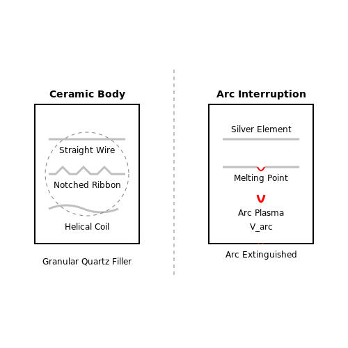
The fusible element's geometry is carefully engineered to control the fuse's time-current characteristics. Common configurations include:
- Straight wire: Simple design with uniform cross-section, suitable for fast-acting applications.
- Notched ribbon: Incorporates narrow sections to create localized heating points, allowing precise control of melting behavior.
- Helical coil: Used in high-voltage fuses to extend arc length during interruption.
Mathematical Modeling of Fuse Operation
The time required for a fuse to blow under overcurrent conditions can be modeled using the I²t characteristic, which relates the energy required to melt the fusible element. The melting time t for a given current I is given by:
where K is a material constant (J/Ω·m³), and A is the cross-sectional area of the fusible element. For a fuse with multiple constrictions (notches), the total melting time is dominated by the narrowest section.
Arc Interruption and Voltage Ratings
When the fusible element melts, an arc forms across the gap. The fuse body must withstand this arc voltage while preventing restrike. The arc voltage Varc can be estimated by:
where E is the electric field strength in the arc plasma (~10 V/mm for air), d is the arc length, and Vcathode and Vanode are the electrode voltage drops. High-voltage cartridge fuses incorporate granular quartz filler to absorb arc energy and facilitate rapid deionization.
Application-Specific Designs
Low-Voltage Industrial Fuses
Class J (600V) and Class RK1 (250V/600V) fuses feature time-delay characteristics for motor starting currents while providing short-circuit protection. Their ceramic bodies withstand high arc energies during fault interruption.
High-Rupture Capacity (HRC) Fuses
Designed for circuits with prospective short-circuit currents exceeding 10 kA, HRC fuses use silver elements with M-effect alloys (e.g., tin droplets) to ensure predictable operation across a wide current range.
Semiconductor Protection Fuses
Fast-acting designs with very low I²t values protect sensitive power electronics. These fuses often incorporate copper elements with precisely calibrated notches to respond within milliseconds during overcurrent events.
Standards and Performance Testing
Cartridge fuses must comply with international standards such as IEC 60269 and UL 248, which specify:
- Breaking capacity (typically 10-200 kA)
- Time-current curves for different fuse classes
- Endurance under cyclic loading
- Temperature rise limits during continuous operation
Blade Fuses: Automotive and Industrial Uses
Construction and Standardization
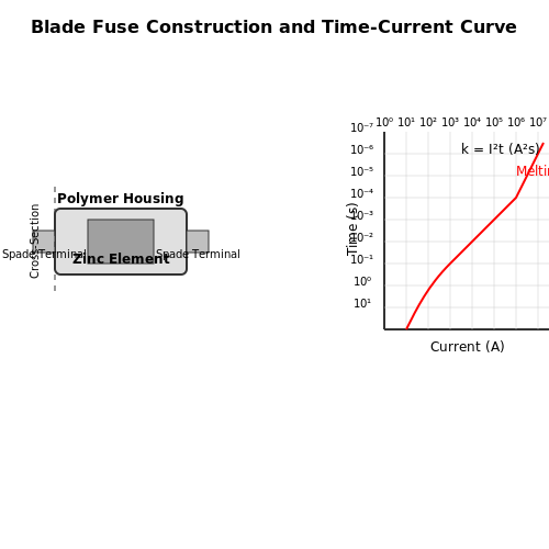
Blade fuses, characterized by their flat, spade-terminal design, are engineered for high-current interruption in compact form factors. The fuse element, typically composed of zinc or copper alloy, is housed within a translucent polymer body, enabling visual inspection of fuse integrity. Standardized dimensions (e.g., ATO, ATC, Mini, Maxi) are governed by ISO 8820-3 and SAE J1284, ensuring cross-compatibility across manufacturers. The current rating (1A to 100A) and voltage rating (32V or 58V DC) are laser-etched on the blade for traceability.
Current Interruption Dynamics
The fuse's time-current characteristic follows an inverse relationship derived from the adiabatic heating equation:
where I is the fault current, t is the melting time, and k is a material constant. For a zinc element (k ≈ 0.04 A²s), a 10A fuse subjected to a 50A fault will interrupt in approximately:
Automotive Applications
Modern vehicles employ blade fuses in power distribution centers (PDCs) for:
- Load-specific protection: Dedicated circuits for ECUs, lighting, and infotainment (typically 5A–20A)
- Inrush current management: Time-delay variants (e.g., MDL type) for inductive loads like fuel pumps
- Crash safety: Pyrofuses (high-speed variants) disconnect batteries within 150ms post-collision
Industrial Implementations
Industrial blade fuses (e.g., JCASE standard) feature:
- Higher interrupting ratings: Up to 2000A at 80V DC for forklift battery systems
- Environmental hardening: IP67-rated housings for agricultural machinery
- Parallel configurations: Current-sharing designs for solar array combiners
Failure Modes and Diagnostics
Common failure mechanisms include:
- Metal migration: Dendritic growth under cyclic thermal stress reduces effective cross-section
- Contact degradation: Fretting corrosion at blade-receptacle interfaces increases resistance
- Partial interruption: Arcing in silica-filled fuses leaves conductive deposits
Infrared thermography reveals anomalous temperature gradients (>10°C above ambient) at compromised connections before catastrophic failure.
Standards and Testing Protocols
Key validation tests per UL 248-14 include:
| Test | Condition | Pass Criteria |
|---|---|---|
| Overload | 135% of rated current | Must interrupt within 1 hour |
| Breaking Capacity | 1000A at rated voltage | No arcing or case rupture |
| Vibration | 10–500Hz, 15g RMS | ΔR < 5% after 4 hours |
2.3 Resettable Fuses (PTC): Functionality and Advantages
Fundamental Operating Principle
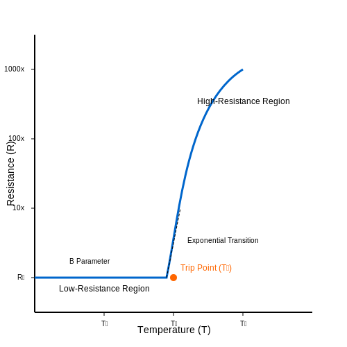
Resettable fuses, also known as positive temperature coefficient (PTC) thermistors, exhibit a nonlinear resistance-temperature relationship. Below a critical temperature (the trip point), their resistance remains low, allowing normal current flow. When an overcurrent condition occurs, Joule heating raises the temperature beyond the trip point, causing a sharp increase in resistance—typically several orders of magnitude—which limits the current to a negligible level. This transition is reversible; once the fault is removed and the device cools, resistance returns to its baseline value.
Here, \( R_0 \) is the resistance at reference temperature \( T_0 \), and \( B \) is the material-specific beta parameter. The exponential dependence on \( T \) explains the abrupt transition at the trip point.
Material Science and Construction
Modern PTC fuses are typically made from polymeric composites doped with conductive particles (e.g., carbon black). Below the trip point, conductive pathways form through percolation networks. As temperature rises, polymer expansion disrupts these pathways, drastically increasing resistance. Crystalline materials like barium titanate (BaTiO3) are used in ceramic PTCs for high-temperature applications.
Key Performance Metrics
- Hold current (\( I_h \)): Maximum steady-state current without tripping.
- Trip current (\( I_t \)): Minimum current causing the device to enter a high-resistance state.
- Time-to-trip: Function of overcurrent magnitude, typically characterized by \( I^2t \) heating dynamics.
- Voltage rating: Maximum DC/AC voltage the device can withstand in the tripped state.
Advantages Over Traditional Fuses
Unlike one-time fuses, PTC devices self-reset after fault clearance, eliminating replacement costs. Their response time is faster than electromechanical breakers for short-circuit conditions, and they offer graceful degradation—repeated tripping cycles do not compromise performance unless thermal or electrical limits are exceeded. They are also immune to mechanical vibration, making them ideal for aerospace and automotive applications.
Practical Design Considerations
Selection requires analysis of:
where \( P_{diss} \) must remain below the device's power dissipation rating. Ambient temperature derating is critical—a PTC rated for 100 mA at 25°C may trip at 80 mA in a 60°C environment due to reduced thermal headroom.
Applications and Case Studies
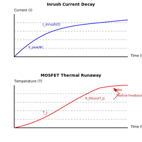
In USB power delivery systems, PTCs protect against short circuits while allowing temporary inrush currents. Telecom equipment uses them for overcurrent protection in subscriber line cards, where manual resetting is impractical. A notable failure mode occurs when a PTC is subjected to sustained overvoltage, causing thermal runaway due to insufficient cooling; this underscores the need for proper voltage derating.
2.4 Time-Current Characteristics and Selection Criteria
Fundamentals of Time-Current Curves
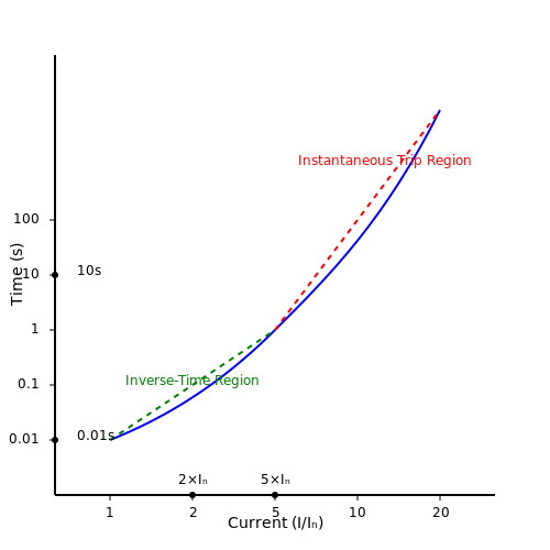
The time-current characteristic (TCC) of a fuse or circuit breaker defines the relationship between the magnitude of overcurrent and the time required for interruption. This curve is typically plotted on a log-log scale, with current (I) on the x-axis and time (t) on the y-axis. The curve consists of two primary regions:
- Instantaneous trip region – Occurs at very high currents (typically 5–30× rated current), where interruption happens in milliseconds due to electromagnetic forces.
- Inverse-time region – Follows an inverse relationship between time and current, where lower overcurrents take longer to interrupt.
Mathematical Modeling of Inverse-Time Characteristics
The inverse-time region is governed by the general equation:
where:
- t = trip time (seconds)
- K = device-specific constant
- I = actual current (A)
- In = rated current (A)
- α = time constant (typically 0.02–2)
For fuses, the melting time tm can be approximated by the I2t relationship:
where Km is the melting integral constant, specific to the fuse element material and geometry.
Selection Criteria for Protection Devices
When selecting fuses or circuit breakers based on time-current characteristics, engineers must consider:
1. Coordination Studies
Proper coordination requires that downstream devices operate faster than upstream devices at all fault currents. The time margin between curves should be:
where tmargin accounts for tolerances (typically 0.1–0.3s).
2. Equipment Damage Curves
Protection curves must lie below the equipment damage curve. For transformers, the ANSI/IEEE C57.109 damage curve follows:
3. Inrush Current Considerations
Devices must withstand temporary inrush currents without nuisance tripping. For motor starting:
where IFL is full-load current.
Practical Application: Curve Interpretation
Consider a 100A circuit breaker protecting a feeder with 500A available fault current:
- At 500A (5× rated), the breaker trips in 0.01s (instantaneous region)
- At 200A (2× rated), trip time extends to 10s (inverse-time region)
Advanced Considerations
Modern solid-state trip units implement adjustable curves using digital signal processing. The algorithm may incorporate:
- Real-time thermal modeling of protected equipment
- Adaptive settings based on load history
- Harmonic distortion compensation
3. Thermal Circuit Breakers: Operation and Limitations
3.1 Thermal Circuit Breakers: Operation and Limitations
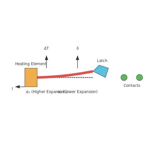
Thermal circuit breakers operate based on the principle of heat generation due to overcurrent conditions. When current exceeds a predefined threshold, the thermal element—typically a bimetallic strip—heats up, bends due to differential thermal expansion, and trips the mechanism to interrupt the circuit. The governing equation for heat generation in the bimetallic strip is derived from Joule heating:
where Q is the heat energy, I is the current, R is the resistance of the strip, and t is the time duration. The deflection δ of the bimetallic strip is proportional to the temperature rise ΔT and the difference in thermal expansion coefficients (α₁ and α₂) of the two metals:
Here, k is a geometric constant dependent on strip dimensions. The trip time-current characteristic follows an inverse relationship, where higher currents result in faster tripping due to accelerated heating.
Key Operational Mechanisms
The bimetallic strip is calibrated to respond to specific current thresholds. Under normal operation, the strip remains stable, but sustained overcurrent causes progressive deflection until mechanical linkage releases the latch, opening the contacts. The time-delay characteristic is critical for distinguishing between temporary surges (e.g., motor startups) and genuine faults.
- Inverse-Time Curve: Trip time decreases nonlinearly with increasing current, modeled by:
where K and p are device-specific constants, and I_n is the rated current.
- Ambient Temperature Compensation: Advanced designs incorporate ambient temperature sensors to adjust trip thresholds, mitigating false trips in varying environments.
Limitations and Practical Considerations
Thermal circuit breakers exhibit inherent limitations that impact their use in precision applications:
- Thermal Inertia: Slow response to short-duration overloads due to the time required for heat transfer.
- Ambient Temperature Dependence: Performance varies with external temperature, necessitating derating in extreme conditions.
- Mechanical Wear: Repeated tripping degrades the bimetallic strip’s elasticity, leading to calibration drift.
For high-frequency or DC applications, eddy currents and magnetic hysteresis in the strip can introduce additional delays. Hybrid designs combining thermal and magnetic tripping mechanisms address some of these limitations by supplementing the thermal response with instantaneous magnetic tripping for short circuits.
Real-World Applications
Thermal circuit breakers are prevalent in residential and industrial distribution panels, where their cost-effectiveness and reliability for moderate overloads are advantageous. They are also used in:
- Motor Protection: Time-delay characteristics prevent nuisance tripping during startup inrush currents.
- Transformer Circuits: Coordinated with upstream devices to ensure selective tripping.
3.2 Magnetic Circuit Breakers: Principles and Use Cases
Operating Principle of Magnetic Circuit Breakers
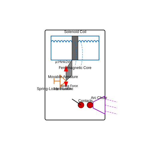
Magnetic circuit breakers operate based on the principle of electromagnetism. When an overcurrent condition occurs, the resulting magnetic field generated by the current flow induces a force sufficient to mechanically trip the breaker. The governing equation for the magnetic force F acting on the trip mechanism is derived from Ampère's force law:
where μ0 is the permeability of free space, I is the current, N is the number of turns in the solenoid, A is the cross-sectional area of the magnetic core, and d is the effective air gap distance. The breaker trips when F exceeds the spring-restoring force calibrated for the rated current.
Construction and Key Components
A magnetic circuit breaker consists of:
- Solenoid coil: Wound around a ferromagnetic core, it generates the magnetic field proportional to the current.
- Armature: A movable iron piece that is pulled by the magnetic force to actuate the trip mechanism.
- Spring-loaded latch: Holds the contacts closed under normal operation but releases when the magnetic force exceeds a threshold.
- Arc chute: Extinguishes the arc formed during contact separation.
Response Characteristics
Unlike thermal breakers, magnetic circuit breakers respond almost instantaneously (typically within milliseconds) to overcurrents, making them ideal for protecting against short circuits. The trip curve is defined by:
where k is the instantaneous trip multiplier (usually 3–20 times the rated current In).
Use Cases and Applications
Magnetic circuit breakers are predominantly used in:
- Industrial power distribution: Protection of motors and transformers against short circuits.
- Automotive systems: Fast-acting protection for high-current circuits in vehicles.
- Renewable energy systems: Safeguarding inverters and battery banks from fault currents.
Advantages Over Thermal Breakers
Key benefits include:
- No thermal inertia: Unaffected by ambient temperature variations.
- High-speed operation: Critical for preventing equipment damage during short circuits.
- Repeatable performance: No degradation over time compared to bimetallic strips.
Limitations and Considerations
Magnetic-only breakers lack overload protection, often necessitating hybrid (thermal-magnetic) designs. Additionally, nuisance tripping can occur in circuits with high inrush currents (e.g., motor startups). Proper coordination with downstream devices is essential to ensure selective tripping.
Hybrid (Thermal-Magnetic) Circuit Breakers
Hybrid circuit breakers combine the principles of thermal and magnetic tripping mechanisms into a single device, optimizing responsiveness across a wide range of fault conditions. These breakers are prevalent in industrial and residential applications where both overload and short-circuit protection are critical.
Operating Principle
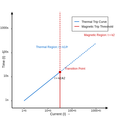
The thermal element, typically a bimetallic strip, responds to prolonged overcurrents by heating and bending, thereby actuating the trip mechanism. The magnetic element, a solenoid or electromagnet, reacts instantaneously to high-magnitude short-circuit currents. The combined response curve is piecewise, with thermal action dominating at lower overcurrents and magnetic tripping taking precedence at higher currents.
where In is the rated current, k1 and k2 are calibration constants, and t is time.
Design Considerations
The integration of thermal and magnetic tripping requires careful coordination to avoid overlap or gaps in protection. Key parameters include:
- Curve Type (B, C, D, etc.): Defines the tripping threshold ratio between magnetic and thermal responses. For example, Type C breakers typically trip at 5–10×In magnetically.
- Time-Current Characteristic (TCC): Must adhere to standards like IEC 60898 or UL 489, ensuring predictable behavior under fault conditions.
- Material Selection: Bimetallic strips are often Ni-Cr or Cu-Mn alloys, while magnetic coils use high-permeability cores to minimize response time.
Practical Applications
Hybrid breakers are favored in:
- Motor Control Circuits: Where inrush currents necessitate delayed tripping (thermal) but fault currents require instantaneous interruption (magnetic).
- Power Distribution Panels: To protect branch circuits from both sustained overloads and bolted faults.
Mathematical Derivation of Trip Time
The total trip time ttotal for a hybrid breaker under an overcurrent I is derived from the thermal and magnetic contributions:
where L and R are the solenoid inductance and resistance, respectively.
3.4 Arc Fault and Ground Fault Circuit Interrupters (AFCI/GFCI)
Operating Principles of GFCI
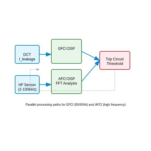
Ground Fault Circuit Interrupters (GFCI) detect leakage currents between the hot and neutral conductors, typically caused by unintended current paths to ground. The core mechanism relies on a differential current transformer (DCT) that measures the imbalance between the outgoing and returning current. If the imbalance exceeds a threshold (typically 4–6 mA), the GFCI trips within 25–40 ms to prevent electric shock.
The trip threshold is derived from the IEC 60755 standard, which defines residual current devices (RCDs) for personnel protection. The mathematical relationship between fault current (If) and trip time (t) follows an inverse-time characteristic:
Arc Fault Detection in AFCI
Arc Fault Circuit Interrupters (AFCI) identify hazardous arcing conditions caused by damaged insulation, loose connections, or broken conductors. Unlike GFCI, AFCI analyzes high-frequency noise (2–100 kHz) superimposed on the 50/60 Hz waveform. Key detection methods include:
- Time-domain analysis: Identifies non-sinusoidal current spikes.
- Frequency-domain analysis: Uses FFT to detect harmonic signatures of arcing.
- Pattern recognition: Machine learning models classify arc signatures vs. benign transients (e.g., motor startups).
Comparative Analysis
| Parameter | GFCI | AFCI |
|---|---|---|
| Primary Protection Goal | Prevent electric shock | Prevent fire from arc faults |
| Threshold Current | 4–6 mA | 5–75 A (series arcs), ≥75 A (parallel arcs) |
| Response Time | 25–40 ms | 100 ms – 1 s (depends on arc energy) |
| Standards | UL 943, IEC 61008 | UL 1699, IEC 62606 |
Practical Implementation Challenges
False tripping remains a critical issue for AFCI due to:
- Electromagnetic interference from switched-mode power supplies.
- Overlapping spectral signatures between arcs and load commutation events.
Modern designs employ adaptive algorithms with real-time noise floor adjustment. For GFCI, nuisance tripping often stems from:
- Capacitive leakage in long cable runs.
- Improper neutral-to-ground bonding.
Advanced Hybrid Designs
Combination AFCI/GFCI devices integrate both protection mechanisms using shared current sensors and multi-core DSPs. The sensor output is processed through parallel detection channels:
Power constraints require optimization of the DSP sampling rate (typically 20–200 kS/s) to balance resolution and energy consumption.
4. Voltage and Current Rating Considerations
4.1 Voltage and Current Rating Considerations
The selection of fuses and circuit breakers hinges critically on their voltage and current ratings, which must align precisely with the electrical system's operational parameters. Misalignment can lead to catastrophic failure modes, including arc flash events or thermal runaway.
Voltage Rating Fundamentals
The voltage rating of a protective device specifies the maximum system voltage it can safely interrupt. Exceeding this rating risks dielectric breakdown, particularly during fault conditions. For AC systems, the RMS voltage must be considered, while DC applications require special attention due to the absence of natural current zero-crossings.
Where the 20% derating factor accounts for voltage transients. High-voltage applications (above 600V) demand additional clearance and creepage distance considerations per IEC 60664.
Current Rating Dynamics
The current rating comprises two distinct parameters:
- Continuous current rating (In): The maximum steady-state current without tripping
- Breaking capacity (Icu): The maximum prospective short-circuit current the device can safely interrupt
The time-current characteristic follows an inverse relationship described by:
Where k is a device constant and n ranges from 1.5-2 for fast-acting fuses to 8-10 for thermal-magnetic breakers.
Coordination Challenges
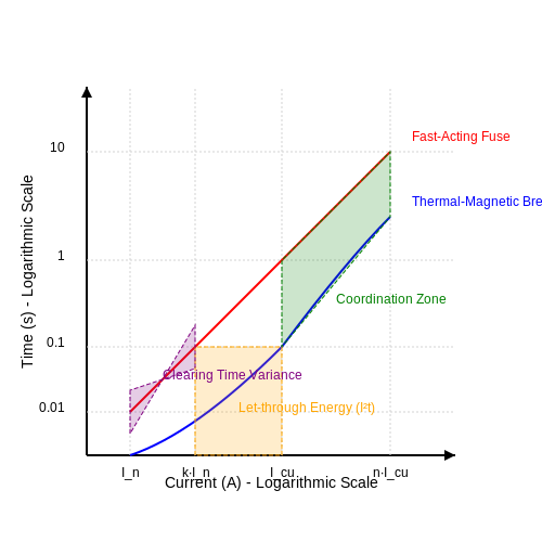
Selective coordination requires careful analysis of:
- Upstream/downstream device time-current curves
- Let-through energy (I2t) values
- System impedance at fault points
The coordination margin between devices should exceed the manufacturer's specified minimum clearing time variance, typically 0.1-0.2 seconds.
Practical Derating Factors
Real-world installations require adjustment for:
- Ambient temperature (5-15% derating per 10°C above 40°C)
- Enclosure heat accumulation (20-30% derating in NEMA 4X enclosures)
- Harmonic distortion (K-factor up to 13 for nonlinear loads)
For parallel conductor installations, the current rating must be multiplied by the number of paths while applying a 0.8-0.9 grouping factor.
Arc Energy Considerations
The incident energy during interruption follows:
Where k is a system constant (0.1-0.3 for LV, 0.5-1.2 for MV). Modern current-limiting devices can reduce E by 90% through ultra-fast (<1/4 cycle) interruption.
4.2 Breaking Capacity and Environmental Factors
Breaking Capacity Fundamentals
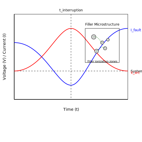
The breaking capacity (or interrupting rating) of a fuse or circuit breaker defines the maximum fault current it can safely interrupt without catastrophic failure. This is determined by the device's ability to extinguish the arc formed during current interruption. The relationship between arc voltage Varc and current I governs the energy dissipation:
For high-current interruptions, the arc voltage must rise rapidly to counteract the system voltage and force current zero. Modern current-limiting fuses achieve this through granular filler materials that ionize and increase arc resistance multiplicatively.
Mathematical Derivation of Critical Parameters
The minimum breaking capacity Ibc required for a given application depends on the prospective short-circuit current Ip and the circuit's time constant τ:
where Q is the quality factor of the circuit:
This shows how inductive systems require higher breaking capacities due to stored magnetic energy.
Environmental Degradation Mechanisms
Three primary environmental factors reduce breaking capacity over time:
- Oxidation: Contact surface degradation increases resistance, raising let-through energy
- Thermal Cycling: Differential expansion fractures current paths in fusible elements
- Humidity: Moisture absorption alters arc quenching medium properties
Accelerated aging tests show breaking capacity degradation follows Arrhenius kinetics:
High-Altitude Derating
At altitudes above 2000m, reduced air density decreases dielectric strength and cooling efficiency. The breaking capacity must be derated by:
where h is altitude in meters. This linear approximation holds up to 5000m.
Practical Design Considerations
For mission-critical applications, engineers should:
- Apply 25% minimum margin above calculated Ibc requirements
- Specify hermetic sealing for corrosive environments
- Use silver or gold plating for high-reliability contacts
- Implement parallel interruption paths for currents above 100kA
Recent advances in vacuum interrupters and SF6 technologies have pushed breaking capacities beyond 200kA for HVDC applications, though these require careful pressure and temperature monitoring.
4.3 Proper Sizing for Circuit Protection
Current Rating and Interrupting Capacity
The primary criterion for sizing a fuse or circuit breaker is the continuous current rating, which must exceed the normal operating current but remain below the conductor's ampacity. For a circuit with a load current IL, the protective device rating IP should satisfy:
The interrupting rating (IR) must exceed the maximum available fault current at the installation point. For a fault current ISC, the IR must satisfy:
Time-Current Characteristics
Protective devices must coordinate with both the load profile and upstream/downstream protection. The time-current curve (TCC) defines the device's response time as a function of current. For a fuse, the melting time tm follows the empirical relationship:
where K and n are constants derived from the fuse material and geometry. Circuit breakers follow more complex inverse-time characteristics governed by thermal-magnetic or solid-state trip units.
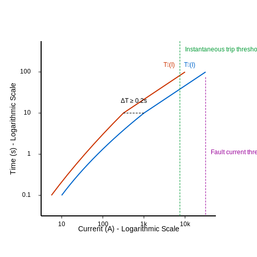
Coordination Studies
Selective coordination requires that downstream devices clear faults before upstream devices operate. For two series-connected breakers with trip curves T1(I) and T2(I), the coordination margin is:
This ensures discrimination for faults below the upstream device's instantaneous trip threshold.
Voltage Drop Considerations
While fuses have negligible impedance during normal operation, their cold resistance Rf contributes to voltage drop in high-current circuits:
For circuits exceeding 30A, voltage drop calculations must include both conductor and fuse resistance.
Environmental Derating
Ambient temperature affects thermal devices. The derating factor D for fuses at temperature Ta is:
Circuit breakers typically require 10-20% derating above 40°C per IEEE C37.13.
Motor Circuit Protection
Motor starting currents necessitate special considerations. The fuse rating Imotor for squirrel-cage induction motors is:
where FLA is the full-load amperage. Circuit breakers must accommodate locked-rotor current without nuisance tripping.
Transformer Protection
Inrush currents in transformers require time-delayed protection. The minimum fuse rating for a transformer with secondary current Isec is:
For circuit breakers, the instantaneous trip must be set above the magnetizing inrush current, typically 8-12× rated current for 0.1s.
4.4 Common Installation Mistakes to Avoid
Incorrect Fuse or Circuit Breaker Sizing
One of the most critical errors in electrical installations is selecting a fuse or circuit breaker with an improper current rating. Oversizing can lead to insufficient protection, allowing excessive current to damage conductors or equipment. Undersizing results in nuisance tripping. The correct sizing must account for:
- Continuous load current (Iload)
- Inrush current (Iinrush) for inductive/capacitive loads
- Ambient temperature derating (for fuses)
The rated current (Irated) should satisfy:
where Iconductor is the ampacity of the wire.
Improper Interrupting Capacity (AIC Rating)
Circuit breakers and fuses must have an Ampere Interrupting Capacity (AIC) exceeding the available fault current at the installation point. A common mistake is using a 10kA breaker in a system with a prospective short-circuit current (ISC) of 20kA. The AIC rating must satisfy:
where Zsource is the upstream impedance. Failure to comply risks catastrophic failure during faults.
Ignoring Voltage Ratings
Protective devices are rated for specific voltage systems (e.g., 250V AC, 600V DC). Using a 250V fuse in a 480V circuit may prevent arcing suppression, leading to insulation breakdown or fire. For DC systems, voltage ratings are often lower than AC equivalents due to the absence of zero-crossing points.
Neglecting Coordination Studies
In cascaded systems, lack of selective coordination between upstream and downstream breakers can cause unnecessary blackouts. Time-current curves (TCCs) must be analyzed to ensure the closest breaker to the fault trips first. Advanced coordination requires:
- Current-limiting fuses for high ISC scenarios
- Zone-selective interlocking in LV/MV switchgear
Mechanical Installation Errors
Poor physical installation compromises reliability. Common issues include:
- Loose connections increasing contact resistance (P = I²R losses)
- Improper torque on breaker terminals (refer to NEMA ABP-1 standards)
- Inadequate ventilation around fuses, leading to thermal derating
Bypassing Safety Features
Tampering with breakers (e.g., disabling trip mechanisms) or replacing fuses with conductive substitutes (e.g., "copper pennies") eliminates protection entirely. Such practices violate NFPA 70 (NEC) Article 240 and IEC 60364 standards.
Overlooking Environmental Factors
Fuses and breakers in corrosive, humid, or high-vibration environments require:
- Hermetic sealing (IP67 or higher)
- Stainless steel hardware for coastal installations
- Anti-vibration mounts in industrial settings
Misapplication of DC vs. AC Devices
DC circuits pose unique challenges due to sustained arcing. A 20A AC breaker may only handle 5A DC at the same voltage. The DC rating must account for:
where k is a manufacturer-specific constant (typically 0.5–0.7).
5. Routine Inspection Techniques for Fuses and Breakers
5.1 Routine Inspection Techniques for Fuses and Breakers
Visual Inspection
Visual inspection is the first and most straightforward diagnostic method for assessing fuse and circuit breaker integrity. For fuses, discoloration, bulging, or a broken filament indicate failure. In circuit breakers, signs of arcing, carbon deposits, or thermal stress on contacts necessitate replacement. Infrared thermography can detect hotspots in breakers under load, revealing poor connections or degraded components before catastrophic failure.
Contact Resistance Measurement
Increased contact resistance in circuit breakers leads to excessive power dissipation, accelerating wear. A micro-ohmmeter measures resistance across closed contacts, with values typically below
Dielectric Strength Testing
Insulation degradation in medium-voltage breakers requires periodic dielectric testing. A hipot tester applies
Mechanical Operation Analysis
Circuit breakers must operate within specified time-force curves. Use a motion analyzer to measure:
- Contact closing velocity ($$ 0.5-2.0 \text{ m/s} $$)
- Opening time ($$ < 50 \text{ ms} $$for molded-case breakers)
- Contact wipe (3-5 mm for air-frame breakers)
Deviations indicate spring fatigue or lubrication issues.
Current-Time Characteristic Verification
For time-delay fuses and breakers, inject stepped currents using a primary injection tester and record trip times. Compare against manufacturer curves, ensuring operation within the
Arc Energy Assessment
Modern breakers incorporate arc quenching systems requiring performance validation. High-speed oscilloscopes capture:
- Arc voltage ($$ 20-200 \text{ V} $$)
- Extinction time ($$ < 5 \text{ ms} $$)
- Let-through energy ($$ I^2t $$)
Exceeding rated
Environmental Stress Testing
Corrosive environments accelerate failure mechanisms. Perform accelerated aging tests by exposing components to:
- 85°C/85% RH for 500 hours (IEC 60068-2-30)
- Salt spray (ASTM B117) for marine applications
- Vibration testing at 5-500 Hz (IEC 60068-2-6)
Post-test insulation resistance must remain above 50% of initial values.
5.2 Testing Circuit Breakers: Tools and Methods
Primary Testing Instruments
Testing circuit breakers requires precision instruments capable of measuring electrical parameters under load and fault conditions. The most critical tools include:
- Micro-Ohmmeter: Measures contact resistance to detect degradation in breaker contacts. A typical threshold for failure is a resistance increase beyond 25% of the manufacturer's specified value.
- Primary Injection Test Set: Injects high currents (up to 10,000A) to verify trip characteristics without relying on secondary circuits. This directly tests the breaker's response to overcurrent.
- Time-Travel Analyzer: Plots the displacement of moving contacts versus time during operation. Abnormalities in the curve indicate mechanical wear or misalignment.
Time-Current Characteristic Verification
The trip curve of a circuit breaker must be validated against its designed time-current characteristics. The test involves:
where t is trip time, I is current, k and α are constants from the manufacturer's curve, and L represents the fixed delay time for long-time overcurrent settings.
Modern test sets automate this process by applying stepped currents and recording trip times, comparing results against the expected curve with ±10% tolerance.
Dielectric Strength Testing
Insulation integrity is verified using:
- Hi-Pot Testing: Applies AC or DC voltage (typically 2× rated voltage + 1kV) between poles and ground for 1 minute. Leakage currents exceeding 1mA per kV indicate insulation breakdown.
- Partial Discharge Measurement: Detects micro-discharges in insulation using high-frequency sensors (>1MHz). PD levels above 10pC at rated voltage suggest impending failure.
Dynamic Contact Resistance Measurement
Unlike static resistance tests, dynamic measurement captures contact behavior during operation:
- A constant DC current (100A typical) is applied through closed contacts
- The breaker is tripped while recording voltage drop across contacts
- Resistance is calculated as R = V(t)/I throughout the opening cycle
Spikes in resistance during opening indicate contact erosion or bounce, while elevated baseline resistance suggests surface contamination.
Thermal Imaging Analysis
Infrared cameras (3-5μm wavelength) identify hot spots under load:
- Temperature differentials >15°C between phases require investigation
- Hot spots at connections indicate loose hardware or oxidation
- Uniform heating of contacts suggests normal current distribution
Mechanical Endurance Testing
Breakers must be cycled to verify mechanical durability:
where N is expected cycles at current I, N0 is rated cycles at I0, and β is the wear coefficient (typically 1.5-2.5 for industrial breakers). Automated test rigs perform up to 10,000 cycles while monitoring operating times and contact resistance.
5.3 Replacing Fuses: Safety Protocols and Best Practices
Pre-Replacement Safety Checks
Before replacing a fuse, ensure the circuit is de-energized by verifying zero voltage across the fuse terminals using a multimeter. For high-voltage systems (>600V), employ a non-contact voltage detector as a secondary confirmation. The voltage measurement should adhere to:
where FSR is the full-scale range of the measuring instrument. Lockout/tagout (LOTO) procedures must be implemented for industrial environments per OSHA 1910.147 standards.
Fuse Selection Criteria
Select a replacement fuse with identical:
- Current rating (Irated): Must match the original fuse's nominal current.
- Voltage rating (Vrated): Must equal or exceed the system voltage.
- Breaking capacity (Imax): Must surpass the prospective short-circuit current.
- Time-current characteristic (e.g., fast-acting, slow-blow).
For pulse-tolerant applications (e.g., inverter circuits), the I²t value must satisfy:
Installation Procedures
For cartridge fuses, ensure proper contact force (typically 5–20 N for blade-type fuses) to prevent arcing. Torque screw-in fuses to manufacturer specifications, usually 0.5–2.5 N·m. Misalignment exceeding 0.5 mm can increase contact resistance by up to 200%.
Post-Replacement Verification
After installation:
- Perform a continuity test to confirm electrical connection (R < 50 mΩ).
- Conduct an insulation resistance test (>1 MΩ at 500V DC).
- Energize the circuit while monitoring inrush current with an oscilloscope or current probe.
Arc Flash Mitigation
When replacing fuses in >240V systems, wear Category 2 PPE (minimum 8 cal/cm² rating). The incident energy (E) can be estimated using the IEEE 1584 equation:
where Cf is a correction factor (1.0 for voltages <1kV) and t is the arcing time in seconds.
Special Cases
High-Voltage Fuses (>1kV)
Use insulated tools with a minimum length of 450 mm for 1kV systems, scaling by 100 mm per additional kV. Replace all three phases simultaneously in polyphase systems to prevent voltage imbalance.
Semiconductor Fuses
Verify the peak let-through current (Ip) remains below the device's I2SM rating. Silicon carbide (SiC) devices may require fuses with 25% faster clearing times than silicon equivalents.
6. Recommended Books and Technical Manuals
6.1 Recommended Books and Technical Manuals
- PDF UL Standards Listing for Industrial Control Products Specifications — Circuit Breakers, Molded Case, and Circuit-breaker Enclosures 30.1.1 31.1.1 75.6.1 1492-MCA • Available up to 100 A • Several configurations of tripping curves and number of poles (NEMA Style) UL 489 DIVQ E197878 Circuit Breakers, Molded Case, and Circuit-breaker Enclosures 30.1.1 31.1.1 75.6.1 140G • Used as main disconnect and feeder ...
- PDF Safe Operation and Maintenance of Circuit Breakers and Switchgear — 1.5 Basic circuit breaker design 5 1.6 Auto reclosing 8 2 Switchgear in an Historic Perspective 13 2.1 Plain break oil circuit breakers 13 2.2 Small oil volume circuit breakers 18 2.3 Air blast circuit breakers 19 2.4 Operating mechanisms 23 2.5 SF 6 and vacuum circuit breakers 23 2.6 Puffer type SF 6 circuit breakers 25
- Guide to the IET Wiring Regulations - Wiley Online Library — C 6.3 Circuit breaker to circuit breaker discrimination 60 C 6.4 Circuit breaker to fuse discrimination 62 C 7 Parallel cables 62 C 7.1 General and BS 7671 requirements 62 C 7.2 Unequal current sharing 63 C 8 Harmonics 63 C 8.1 Requirements 63 C 8.2 Harmonic assessment 63 C 9 Standard ˜ nal circuit designs 64
- Electric Fuses (Energy Engineering) 3rd Edition - amazon.com — The book begins by describing the very first electric fuses and their applications, their later development, the introduction of standard specification and the spread of the use of fuses; and ends focusing on the updated national and international standards regarding fuses and the quality assurance and inspection methods used during manufacture ...
- PDF Guide to Lowbvoltage Switch and Fusegear Devices - Beama — 5.5.1 Selectivity between fuse-links 18 5.5.2 Selectivity between fuse-links and other protective devices 19 5.5.2.1 Selectivity of circuit-breakers upstream of fuse-links 19 5.5.2.2 Selectivity of fuse-links upstream of circuit-breakers 19 2021 LOW VOLTAGE FUSE GUIDE.qxp_BEAMA CAD guide 17/12/2021 13:38 Page 4
- PDF Practical Power Systems Protection for Engineers and Technicians — 8.5 Reasons why breakers and contactors fail to trip 121 8.6 Capacity storage trip units 122 Chapter 9 — Relays 125 9.1 Introduction 125 9.2 Principle of the construction and operation of the IDMTL relay 126 9.3 Factors influencing choice of plug setting 138 9.4 The new era in protection - microprocessor vs electronic vs
- PDF Outdoor SF6 Circuit Breaker - Type OHB - ABB — 6. Instructions for circuit-breaker operation 6.1. Operating and signaling parts 6.2. Safety indications 6.3. Circuit-breaker closing and opening operations 7. Installation 7.1. General 7.2. Normal installation conditions 7.3. Preliminary operations 7.4. Preparing the fixing surface and circuit-breaker fixing 7.5. Assembly for the telescopic ...
- PDF General Guidelines for Electronic Equipment - Dau — MIL- HDBK -11991 Electrical, Electronic and Electro-mechanical Equipment, Guided Missile and Associated Weapon Systems, Design of . MIL-F-18870 Fire Control Equipment, Naval Shipboard, General Specification for. MIL-PRF-28800 Test Equipment for Use with Electrical and Electronic Equipment, General Specification for. 4.
- PDF A Guide to United States Electrical and Electronic Equipment ... - NIST — This guide addresses electrical and electronic consumer products, including those that will . In addition, it includes electrical and electronic products used in the workplace as well as electrical and electronic medical devices. The scope does not include vehicles or components of vehicles, electric or electronic toys, or recycling ...
- PDF Industrial Control Wiring Guide - ICDST — Technical Document of the equipment so that it can be inspected should there be a query by the authorities regarding the equipment's safety or performance. The best way to show compliance with a regulation is to use recognised standards in the design and con- ... Circuit-breakers. Part 3: Switches, disconnectors, switch-discon-nectors and ...
6.2 Industry Standards and Safety Regulations
- PDF Fuses Versus Circuit Breakers for Low Voltage Applications — [1] National Electrical Code®, NFPA 70, 2011 [2] UL Standard for Safety for Molded-Case Circuit Breakers, Molded-Case Switches and Circuit-Breaker Enclosures, UL 489, 2009 [3] IEEE Recommended Practice for Protection and Coordination of Industrial and Commercial Power Systems, IEEE Std 242-2001 [4] UL Standard for Safety for Low-Voltage Fuses
- PDF General Guidelines for Electronic Equipment - Dau — Circuit breakers should not be used as switches unless such breakers have been specifically designed and tested for that type service. 4.2.2 Spare fuses . When fuses are used, a minimum of one spare fuse for each size and rating but a quantity of not less than 10 percent of the total should be incorporated in the equipment and should be ...
- Front Matter - Wiley Online Library — 5.3 Armouring as a cpc 5.4 Automatic disconnection for submains 6 Discrimination co-ordination 6.1 Principles and system co-ordination 6.2 Fuse-to-fuse discrimination 6.3 Circuit breaker to circuit breaker discrimination 6.4 Circuit breaker to fuse discrimination 7 Parallel cables 7.1 General and 7671 requirements
- IEC 60934:2019 - Circuit breakers for equipment (CBE) - iTeh Standards — IEC 60934:2019 is applicable to mechanical switching devices designed as "circuit‑breakers for equipment" (CBE) for household and similar applications. CBEs according to this document are intended to provide protection to circuits within electrical equipment including its components (e.g. motors, transformers, internal wiring). This document covers also CBEs applicable for protection of ...
- PDF Standards and ratings for the application of molded-case ... - IEEE — The short-circuit rating of a circuit breaker is defined by its interrupting capacity, the maximum current the breaker can safely interrupt. MCCBs and ICCBs are available with three-phase short-circuit current ratings that vary based on the system voltage and the breaker design.
- What are the main international standards for low-voltage electrical ... — Many Canadian regulations and standards require electrical products sold in the market to be CSA certified, especially in the fields of construction, industry, and consumer goods.
- PDF A Guide to United States Electrical and Electronic Equipment ... - NIST — 16 CFR 1229 Safety Standard for Infant Bouncer Seats requires that all infant bouncer seats comply with all applicable provisions of ASTM F2167-17, which has been incorporated by reference into this regulation.
- PDF Standard for Fuse Applications - ANSI Webstore — cedures for low-voltage fuses. This publication applies to all classifications of fuses used for overcurrent protection of distribution, utilization, and control equipment used for power, heating, and lighting loads for commercial, institutional, and industrial use in nonhazardou
- PDF Electrical Safety Guideline - INGAA — Electrical Safety Program. This guidance does not address design activities, nor does it address all options available f The responsibility for an electrical safety program should be delegated to someone with a complete knowledge of electricity, safe electrical work practices, and the appropriate standards for installation and performance.
- PDF Presentation - IEEE — Method for listing specific breakers was not defined in the standard and was based on a comparison of the "published" instantaneous clearing time between the tested breaker and non-tested circuit breakers.
6.3 Online Resources and Educational Materials
- PDF Safe Operation and Maintenance of Circuit Breakers and ... - IDC-Online — 1.5 Basic circuit breaker design 5 1.6 Auto reclosing 8 2 Switchgear in an Historic Perspective 13 2.1 Plain break oil circuit breakers 13 2.2 Small oil volume circuit breakers 18 2.3 Air blast circuit breakers 19 2.4 Operating mechanisms 23 2.5 SF 6 and vacuum circuit breakers 23 2.6 Puffer type SF 6 circuit breakers 25
- Section 5.3: Fuses and Circuit Breakers — Section 5.3: Fuses and Circuit Breakers # What Are Fuses and Circuit Breakers? # Key Information: Fuses and circuit breakers are electrical components used to protect other circuit components from current overloads Let's talk about the first line of defense in electrical safety: fuses and circuit breakers are devices designed to protect electrical circuits from overcurrent conditions. These ...
- CBLM 6 Terminate & Connect Electrical Wiring & Electronic Circuits - Scribd — CBLM 6 Terminate & Connect Electrical Wiring & Electronic Circuits - Free download as Word Doc (.doc / .docx), PDF File (.pdf), Text File (.txt) or read online for free. This competency-based learning module provides training materials to terminate and connect electrical wiring and electronic circuits. The module contains information sheets, job sheets, operation sheets, and activity sheets ...
- 4.6: Current Limiting - Fuses and Circuit Breakers — Figure 4.6.3 : Schematic symbols for fuses: IEC (top and middle), ANSI (bottom). Fuses are generally inexpensive and effective. The obvious downside to a fuse is that they need to be replaced once they do their job. A circuit breaker solves this problem. A circuit breaker, or just breaker for short, can be thought of as a resettable fuse.
- Fuses & Circuit Breakers - Physics: AQA GCSE Higher - Seneca — Fuses and circuit breakers protect us from electrical appliances by stopping the flow of electric current flow if it gets too high. ... 1.3.1 Energy Resources. 1.3.2 Fossil Fuels. 1.3.3 Geothermal Energy. 1.3.4 Wind Energy. 1.3.5 Water Energy. ... Tutors are matched to your specific learning needs. 30+ school subjects covered. Book a free trial ...
- Electricity Section 6.3 Flashcards - Quizlet — Study with Quizlet and memorise flashcards containing terms like fuses, circuit breakers, electrocution and others. ...
- Electricity 6.3 Flashcards - Quizlet — Study with Quizlet and memorize flashcards containing terms like How do series circuits differ from parallel circuits?, What is the function of a circuit breaker? A fuse?, How can you calculate electrical power? and more.
- PDF Chapter (2) Circuit Breakers - BU — switch is initially closed along with the circuit breaker. So when contacts C 1, C 2 and C 3 are closed, the current flows through trip coil of circuit breaker. This activates the trip coil which opens the circuit breaker. As auxiliary switch is mechanically coupled with the circuit breaker, it also gets opened. This interrupts the current ...
- Fuses and Circuit Breakers - InstrumentationTools - Inst Tools — The fuses are held by spring metal clips, the clips themselves being permanently connected to the circuit conductors. The base material of the fuse holder (or fuse block as they are sometimes called) is chosen to be a good insulator. Another type of fuse holder for cartridge-type fuses is commonly used for installation in equipment control panels, where it is desirable to conceal all ...
- Fuse Tutorial | DigiKey - Digi-Key Electronics — A fuse should be de-rated by 25% at room temperature, meaning if there is a 7.5 amp circuit, a 10 amp fuse should be used at 25˚C. Voltage ratings on a fuse can be higher than the voltage on the circuit, but not lower. At the end of the day, a simple fuse is a great way to effectively protect a circuit. Resources "Fuseology". Retrieved 18 ...