Grounding and Bonding
1. Definition and Purpose of Grounding
Definition and Purpose of Grounding
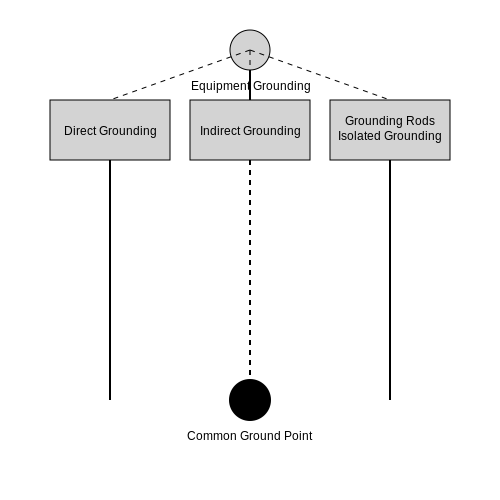
Grounding, in electrical engineering, refers to the intentional connection of an electrical circuit or equipment to the Earth or a conductive body that serves in place of the Earth. The primary objectives are:
- Safety: To provide a low-impedance path for fault currents, enabling protective devices to operate and prevent hazardous voltages.
- Voltage stabilization: To establish a reference potential (typically zero) for system voltages.
- Noise reduction: To mitigate electromagnetic interference (EMI) by providing a return path for unwanted currents.
Fundamental Principles
The effectiveness of grounding depends on soil resistivity (ρ) and electrode geometry. The resistance (R) of a grounding electrode is given by:
where L is the electrode length and d is its diameter. For complex electrode arrangements, mutual coupling effects must be considered:
Rm represents mutual resistance between electrodes.
Practical Implementation
Industrial grounding systems typically employ:
- Copper-clad steel rods (5/8" to 1" diameter, 8-10 ft deep)
- Buried horizontal conductors forming a ground grid
- Exothermic welds for permanent connections
The step potential (Vstep) near faulted equipment must satisfy:
where Ig is ground fault current and Δr is the stride length (typically 1m).
High-Frequency Considerations
At frequencies above 1 MHz, grounding conductor inductance (L ≈ 1 μH/m) dominates:
This necessitates:
- Minimizing conductor length-to-width ratio
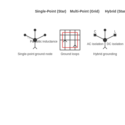
- Using multipoint grounding for RF systems
- Implementing ground planes instead of wires
1.2 Definition and Purpose of Bonding
Bonding refers to the intentional electrical interconnection of conductive objects to ensure equipotentiality, regardless of whether they are part of the electrical system or not. Unlike grounding, which establishes a reference to earth, bonding creates a low-impedance path between metallic components to eliminate potential differences that could result in hazardous touch voltages, electromagnetic interference (EMI), or arcing.
Fundamental Principles
The primary objective of bonding is to maintain all conductive surfaces at the same potential, governed by Ohm’s Law:
where V is the potential difference, I is fault current, and Z is the impedance of the bonding path. For effective bonding, Z must be minimized to ensure that V remains below hazardous thresholds during fault conditions. The National Electrical Code (NEC) specifies maximum bonding impedances—typically under 1 ohm—for safety-critical systems.
Types of Bonding
- Structural Bonding: Interconnects building steel, conduit, and enclosures to prevent static discharge and fault current divergence.
- Equipment Bonding: Ensures metallic casings of devices remain at the same potential as the electrical system ground.
- Lightning Protection Bonding: Integrates air terminals, down conductors, and grounding electrodes to equalize potentials during strikes.
Practical Applications
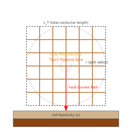
In high-voltage substations, bonding grids—comprising copper conductors laid in a mesh pattern—are buried to mitigate step and touch potentials. The grounding grid resistance Rg can be approximated by Sverak’s equation:
where ρ is soil resistivity, r is grid radius, and LT is total conductor length. Without bonding, potential gradients during faults could exceed IEEE Std 80 limits (e.g., 5 kV for 0.1–0.5 s).
Standards and Compliance
Bonding practices are codified in:
- NFPA 70 (NEC Article 250)
- IEEE Std 1100 (Emerald Book)
- IEC 60364-4-41
For example, NEC 250.96 mandates bonding of raceways and enclosures containing service conductors, with bonding jumpers sized per Table 250.102(C)(1) based on the upstream overcurrent protection rating.
1.3 Key Differences Between Grounding and Bonding
Functional Objectives
Grounding and bonding serve distinct yet complementary roles in electrical systems. Grounding establishes a reference potential, typically earth, to stabilize system voltage and provide a safe path for fault currents. In contrast, bonding ensures equipotentiality between conductive surfaces, minimizing potential differences that could lead to hazardous touch voltages or electromagnetic interference (EMI).
Current-Carrying Behavior
Under normal conditions, grounding conductors should carry negligible current. However, during faults, they conduct substantial current to facilitate protective device operation. Bonding conductors, on the other hand, are not intended to carry operational current but must handle fault currents when needed. The required cross-sectional area for bonding conductors is often calculated using:
where I is fault current, t is duration, and k is a material constant (e.g., 143 for copper).
System Topology
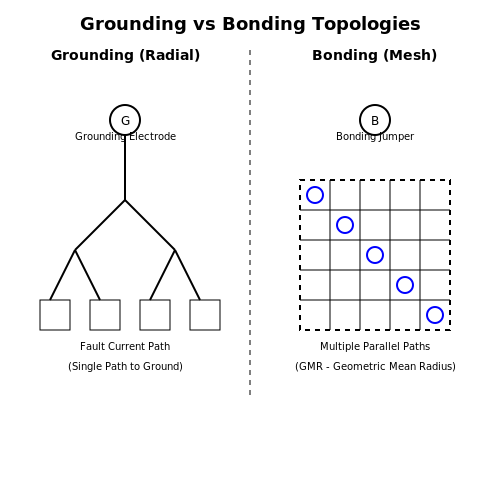
Grounding systems employ radial topologies with single-point connections to earth electrodes, while bonding networks form mesh structures. In high-frequency applications (>100 kHz), bonding meshes must maintain low impedance through geometric mean radius (GMR) optimization:
where l is conductor length and GMR depends on stranding configuration.
Practical Implementation
- Grounding requires deep-driven electrodes (≥2.5 m) to achieve stable earth contact resistance, often enhanced with chemical backfill
- Bonding uses exothermic welds or listed clamps to maintain permanent low-impedance connections between structural members
- In substations, grounding grids must limit step potential to <75 V, while bonding jumpers prevent circulating currents between parallel conduits
Measurement Techniques
Grounding effectiveness is quantified via fall-of-potential tests (IEEE Std 81), measuring resistance to remote earth. Bonding integrity requires milliohm-meter verification (ASTM B539) with test currents ≥10 A to overcome contact film resistance.
2. Solidly Grounded Systems
2.1 Solidly Grounded Systems
In a solidly grounded system, the neutral point of a power source (e.g., transformer or generator) is directly connected to earth without intentional impedance. This configuration ensures minimal voltage rise during ground faults, providing a stable reference potential. The absence of impedance allows fault currents to reach magnitudes limited only by system impedance and source capacity, facilitating rapid overcurrent protection operation.
Fault Current Analysis
For a bolted line-to-ground fault in a solidly grounded system, the fault current If is determined by the system voltage VLN and the sequence impedances:
where Z1, Z2, and Z0 are the positive, negative, and zero-sequence impedances, respectively. In solidly grounded systems, Z0 is dominated by the transformer's zero-sequence impedance, typically much lower than Z1 or Z2.
Advantages
- Overvoltage suppression: Prevents transient overvoltages during line-to-ground faults by providing a low-impedance path to earth.
- Fault detection: High fault currents ensure reliable operation of fuses and circuit breakers.
- Equipment safety: Limits touch voltages to safer levels during faults, complying with IEEE Std 80.
Disadvantages
- High fault currents: May exceed equipment withstand ratings, requiring robust protective devices.
- Service interruptions: Single-phase faults trip the entire circuit, reducing reliability.
- Arc flash hazards: Elevated energy dissipation increases arc flash risks, necessitating PPE and arc-resistant switchgear.
Practical Applications
Solid grounding is prevalent in:
- Low-voltage systems (<600V), where equipment insulation is designed to withstand full line-to-line voltage.
- Industrial plants requiring immediate fault clearing to protect personnel and machinery.
- Utility distribution networks (e.g., 4-wire multi-grounded neutral systems).
Design Considerations
The grounding conductor's cross-sectional area must satisfy:
where If is the fault current (A), t is the fault duration (s), and K is a material constant (e.g., 0.143 for copper). The National Electrical Code (NEC Article 250) mandates minimum sizes based on system voltage and fault current levels.

2.2 Resistance Grounded Systems
Resistance grounded systems introduce a deliberate impedance between the neutral point of a power system and ground, typically using a resistor. This configuration limits fault currents while maintaining system stability, making it prevalent in industrial and medium-voltage applications where transient overvoltages must be suppressed.
Operating Principle
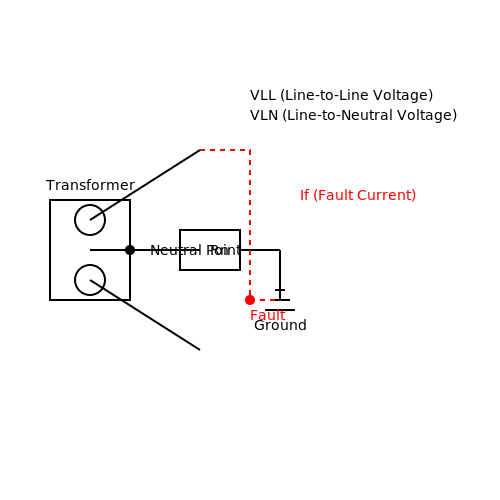
In a resistance grounded system, the neutral point of a transformer or generator is connected to ground through a resistor Rn. During a line-to-ground fault, the resistor limits the fault current If to a manageable value, determined by:
where VLL is the line-to-line voltage. The resistance is chosen to balance between fault current limitation (typically 5–600 A) and ensuring sufficient current for protective relay operation.
Types of Resistance Grounding
Low-Resistance Grounding (LRG)
Uses resistors with If ≥ 100 A, primarily for systems above 1 kV. LRG provides:
- Fault detection clarity: Enables precise relay coordination.
- Arc suppression: Reduces arc-flash hazards by limiting energy.
- Voltage stabilization: Prevents transient overvoltages during faults.
High-Resistance Grounding (HRG)
Designed for If ≤ 10 A, common in critical facilities (hospitals, data centers). HRG offers:
- Continuous operation: Allows the system to remain online during a single line-to-ground fault.
- Minimal damage: Fault currents are below ignition thresholds for arc flashes.
- Harmonic mitigation: Neutral resistor dampens third-harmonic oscillations.
Design Considerations
The resistor value Rn is derived from the system's charging capacitance C to prevent resonant overvoltages. For HRG, the Petersen coil condition is adapted:
where ω is the angular frequency (377 rad/s for 60 Hz). This ensures the fault current remains resistive-dominant, avoiding phase-to-phase voltage escalation.
Practical Implementation
Resistors are rated for:
- Continuous duty: Must withstand VLN (line-to-neutral voltage) indefinitely.
- Fault duration: Typically 10 sec–1 min, based on relay clearing times.
Modern systems integrate ground-fault monitors that measure neutral current asymmetry (I0) to detect incipient faults before escalation.
Case Study: Industrial Plant HRG
A 4.16 kV system with C = 2 µF per phase uses an HRG resistor sized at:
yielding a fault current of 5.4 A, below the 10 A HRG threshold. The design eliminated nuisance tripping while maintaining compliance with NFPA 70E arc-flash safety standards.
2.3 Ungrounded Systems
Ungrounded systems operate without an intentional connection to earth or a conductive body serving as a reference ground. These systems are often employed in specialized industrial and medical applications where uninterrupted operation is critical, such as in continuous process manufacturing or life-support equipment. The absence of a ground reference introduces unique challenges in fault detection, transient overvoltage suppression, and personnel safety.
Electrical Characteristics and Behavior
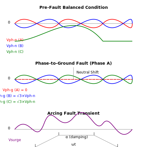
In an ungrounded system, the line-to-ground voltages are not fixed but instead float relative to the system's capacitance-to-ground. Under balanced conditions, the neutral point remains at or near earth potential due to distributed capacitive coupling. However, a single line-to-ground fault shifts the system's neutral, causing the healthy phases to operate at line-to-line voltage relative to ground. The phase-to-ground voltage Vph-g on unfaulted phases becomes:
where Vph-n is the nominal phase-to-neutral voltage. This overvoltage condition stresses insulation systems and necessitates derating of components.
Fault Detection Challenges
Since no low-impedance path exists for ground fault currents, traditional overcurrent protection devices often fail to operate during single-line faults. Instead, ground detection methods rely on:
- Neutral voltage displacement monitoring via broken-delta potential transformers
- Residual current measurement using core-balance current transformers
- Insulation monitoring devices that inject low-frequency test signals
The fault current If in an ungrounded system is purely capacitive and can be approximated by:
where C0 is the system's zero-sequence capacitance per phase and ω is the angular frequency. Typical values range from 0.5–5 A for medium-voltage systems.
Transient Overvoltage Risks
Arcing ground faults in ungrounded systems create high-frequency transients through the restrike phenomenon. Each arc extinction and reignition cycle generates voltage surges proportional to:
where VLL is the line-to-line voltage and α represents the system damping coefficient. These transients frequently exceed 5–6 per unit, necessitating surge protection devices rated for repetitive duty.
Practical Applications and Limitations
Ungrounded systems find use in:
- Petrochemical plants where service continuity outweighs shock risk
- Hospital isolation power systems per NFPA 99 requirements
- Legacy industrial facilities with existing infrastructure
Modern implementations often incorporate high-resistance grounding (HRG) to mitigate transient overvoltages while maintaining most benefits of ungrounded operation. The grounding resistor value Rn is typically selected to limit fault current to:
where Iallowed is usually set between 5–25 A depending on system voltage and capacitance.
2.4 Reactance Grounded Systems
Fundamentals of Reactance Grounding
Reactance grounding employs an inductive reactance, typically a reactor or grounding transformer, between the neutral point of a power system and ground. The primary purpose is to limit fault currents while maintaining system stability. Unlike resistance grounding, which dissipates energy as heat, reactance grounding stores energy in the magnetic field of the inductor. The grounding reactance Xn is chosen such that:
where X0 is the zero-sequence reactance of the system, and k is a dimensionless factor typically ranging from 1 to 10. This ensures the ground fault current If is limited to a manageable value, often 25-60% of the three-phase fault current.
Transient Overvoltage Considerations
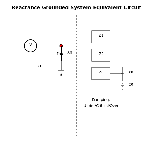
Reactance grounding mitigates transient overvoltages by providing a path for zero-sequence currents. During a line-to-ground fault, the system behaves as a series RLC circuit. The critical parameter is the grounding reactance-to-capacitance ratio, which determines whether the system is:
- Underdamped (oscillatory transients, Xn < Xcrit)
- Critically damped (Xn = Xcrit)
- Overdamped (non-oscillatory, Xn > Xcrit)
The critical reactance Xcrit is derived from the system's distributed capacitance C0:
Practical Implementation
Modern reactance grounded systems often use zig-zag grounding transformers or Peterson coils. Key design considerations include:
- Fault current limitation: Typically set to 25-100 A for medium-voltage systems (2.4-34.5 kV)
- Neutral displacement voltage: Must remain below 130% of phase voltage during faults
- Harmonic suppression: Third-harmonic filters are often required due to nonlinear magnetization
The equivalent circuit for analysis combines positive-, negative-, and zero-sequence networks:
Case Study: Industrial Plant Application
A 13.8 kV manufacturing facility implemented reactance grounding after experiencing repeated equipment failures with solid grounding. The design parameters were:
| Parameter | Value |
|---|---|
| System Capacitance (C0) | 0.5 μF/phase |
| Chosen Reactance (Xn) | 1500 Ω |
| Resultant Fault Current | 38 A |
This configuration reduced arc-flash hazards while maintaining sufficient current for protective relay operation. The neutral displacement during faults was measured at 78% of phase voltage, well within IEEE Std 142-2007 limits.
Comparison with Alternative Methods
Reactance grounding occupies a middle ground between low-resistance and high-resistance approaches:
- Vs. Low-Resistance: Lower fault currents (5-20% vs. 25-100%), but higher transient overvoltages
- Vs. High-Resistance: Better fault detection capability, but requires larger equipment
- Vs. Resonant Grounding: Less precise tuning needed, but more sensitive to system changes
The choice depends on system voltage, fault tolerance requirements, and maintenance capabilities. Reactance grounding is particularly advantageous in:
- Systems with frequent line-to-ground faults
- Networks with significant distributed capacitance
- Environments where service continuity is critical
3. Equipotential Bonding
3.1 Equipotential Bonding
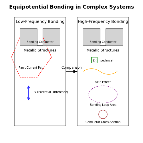
Equipotential bonding ensures that all conductive parts within a system are maintained at the same electrical potential, minimizing the risk of hazardous voltage differences. This is critical in environments where fault currents, lightning strikes, or static discharge could create dangerous potential gradients.
Fundamental Principles
The primary objective of equipotential bonding is to eliminate potential differences between exposed conductive surfaces and the grounding system. The voltage difference V between two points is given by:
where E is the electric field and dl is the differential path length. In an ideal equipotential system, V = 0 for all points P1 and P2 within the bonded region.
Implementation in Complex Systems
For large-scale installations (e.g., industrial plants, data centers), equipotential bonding requires:
- Low-impedance connections between all metallic structures
- Proper sizing of bonding conductors based on fault current levels
- Integration with lightning protection systems
The required cross-sectional area A of a bonding conductor can be derived from the adiabatic equation:
where I is the prospective fault current, t is the fault duration, and k is a material constant.
High-Frequency Considerations
At RF frequencies (above 100 kHz), traditional bonding methods become ineffective due to skin effect and conductor inductance. The impedance Z of a bonding strap at high frequency is:
where ω = 2πf. This necessitates:
- Use of wide, flat conductors instead of round wires
- Multiple parallel bonding paths for critical systems
- Careful attention to bonding loop areas
Practical Applications
In aircraft and spacecraft, equipotential bonding must account for:
- Dissimilar metal corrosion at bonding points
- Thermal expansion differentials
- Vibration resistance requirements
The bonding resistance between components should typically measure less than 2.5 mΩ when verified with a 4-wire micro-ohmmeter.
Measurement and Verification
Effective bonding is verified through:
- Continuity testing at 200 mA DC
- High-current testing (25A or more for critical systems)
- Transient impedance measurements for high-speed systems
The time-domain reflectometry (TDR) method provides the most comprehensive assessment of bonding path integrity, particularly for distributed systems.
3.2 Bonding Conductors and Jumpers
Bonding conductors and jumpers serve as critical components in establishing equipotential bonding, ensuring electrical continuity between metallic structures, enclosures, and grounding systems. Their design and implementation must comply with stringent standards such as NEC Article 250 and IEEE Std 80 to mitigate hazards like step potential, touch potential, and electromagnetic interference (EMI).
Material Selection and Conductivity
The effectiveness of a bonding conductor depends on its material properties, primarily conductivity and corrosion resistance. Copper, due to its high conductivity (σ ≈ 5.96 × 10⁷ S/m), is the most common choice, though aluminum (σ ≈ 3.5 × 10⁷ S/m) is used where weight or cost is a concern. The resistance of a bonding jumper can be derived from:
where ρ is resistivity, L is length, and A is cross-sectional area. For a copper conductor with L = 1 m and A = 10 mm²:
Mechanical and Thermal Considerations
Bonding jumpers must withstand mechanical stress (e.g., vibration, thermal expansion) and fault currents without degradation. The minimum cross-sectional area for a bonding jumper is determined by the prospective fault current If and duration t:
where K is a material constant (≈ 226 for copper). For a 10 kA fault lasting 0.1 s:
Installation Practices
Proper installation ensures low-impedance paths and durability:
- Direct Metal-to-Metal Contact: Surfaces must be cleaned of oxides or coatings; exothermic welding or compression lugs are preferred over mechanical clamps.
- Routing: Avoid sharp bends to reduce inductance (L ∝ loop area).
- Corrosion Protection: Antioxidant compounds (e.g., zinc-rich paint) are applied in corrosive environments.
High-Frequency Bonding
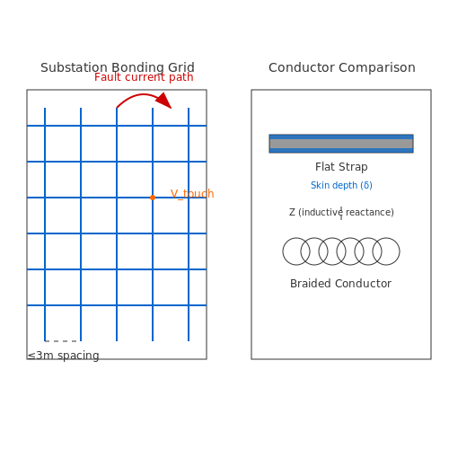
At high frequencies (e.g., RF systems or lightning protection), skin effect and inductance dominate impedance. Flat straps or braided conductors are used to minimize inductive reactance:
where ω is angular frequency. A 10 cm straight wire with 1 μH inductance exhibits 6.28 Ω reactance at 1 MHz.
Case Study: Substation Bonding Grid
A substation grounding grid employs bonded conductors spaced ≤ 3 m apart, forming a mesh. The touch voltage Vtouch is calculated per IEEE Std 80:
where Km is a geometric factor, Ki accounts for grid irregularity, ρ is soil resistivity, IG is grid current, and Lm is mesh conductor length.
3.3 Bonding for Lightning Protection
Fundamental Principles of Bonding in Lightning Protection Systems
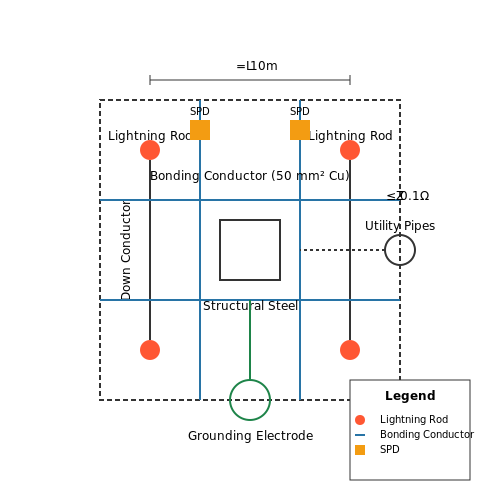
Bonding in lightning protection systems ensures equipotentialization between metallic structures, minimizing the risk of side flashes or potential differences during a lightning strike. The primary objective is to create a low-impedance path that equalizes transient voltages across all conductive elements. This is achieved by interconnecting:
- Lightning rods (air terminals)
- Down conductors
- Structural steel
- Utility pipes and conduits
- Electrical grounding systems
The bonding impedance Zb must satisfy:
where Vpeak is the tolerable touch voltage (typically <1 kV for personnel safety) and Ipeak is the lightning current (often 200 kA for Class I systems per IEC 62305).
Bonding Conductor Sizing
Conductor cross-sectional area A is derived from the adiabatic heating equation:
where:
- I = lightning current (kA)
- t = duration (μs)
- K = material constant (245 for copper)
- Tm = melting temperature (°C)
- Ta = ambient temperature (°C)
For a 200 kA strike with 100 μs duration, copper bonding conductors typically require ≥50 mm² cross-section.
Mesh Bonding Networks
High-risk facilities employ mesh-common bonding networks (CBN) with characteristic lengths Lc:
where c is the speed of light and fmax is the highest frequency component of the lightning pulse (typically 1 MHz). This yields maximum mesh spacing of 30 m for general structures.
Practical Implementation
Effective bonding requires:
- Exothermic welding for permanent connections with <0.1 mΩ resistance
- Clamped bonds with pressure-contact surfaces exceeding 50 N/mm²
- Surge protective devices (SPDs) at bonding interfaces between dissimilar systems
The bonding continuity must be verified through:
- 4-wire milliohmmetry (resolution ≤1 mΩ)
- Time-domain reflectometry for long conductor runs
- High-current testing (≥25 A DC) per IEEE Std 837
Case Study: Telecommunications Tower Bonding
A 150 m tower with 3 down conductors requires circumferential bonding rings at 30 m intervals. Measured bonding resistances between:
- Tower legs: 2.3 mΩ ±0.5 mΩ
- Antenna mounts: 3.1 mΩ ±0.7 mΩ
- Ground grid connections: 1.8 mΩ ±0.3 mΩ
Potential rise during an actual 189 kA strike measured 42 kV at the top ring, with <1.2 kV differential between adjacent metallic components.
4. Electrical Shock Hazards and Mitigation
4.1 Electrical Shock Hazards and Mitigation
Mechanisms of Electrical Shock
Electrical shock occurs when a current passes through the human body, disrupting normal physiological functions. The severity depends on three primary factors: current magnitude, duration of exposure, and path through the body. The threshold of perception is approximately 1 mA, while currents above 10 mA can cause involuntary muscle contractions (let-go threshold). Ventricular fibrillation, often fatal, typically occurs at currents exceeding 100 mA.
Where Rbody varies from 1 kΩ (wet skin) to 100 kΩ (dry skin), and Rcontact depends on electrode-skin interface conditions.
Step and Touch Potential Hazards
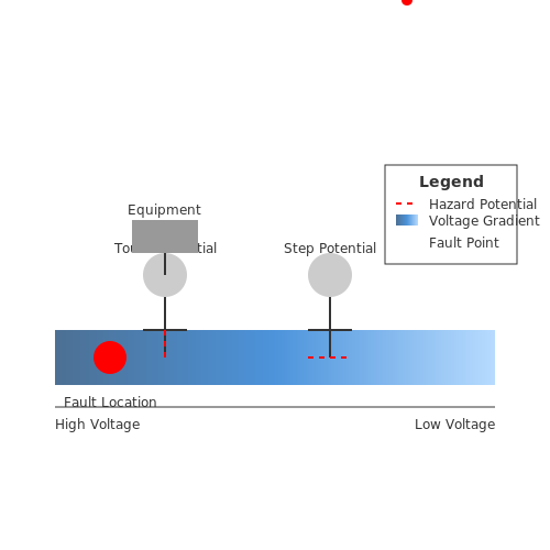
During ground faults, potential gradients create hazardous voltage differences:
- Step potential: Voltage between feet (typically 1 m apart)
- Touch potential: Voltage between energized object and feet
where ρ is soil resistivity, Ig is ground fault current, and r is distance from fault point.
Mitigation Techniques
Equipment Grounding
Proper equipment grounding ensures fault currents have a low-impedance path to earth, facilitating protective device operation. The ground-fault current path must satisfy:
where Itrip is the overcurrent device rating.
Ground-Fault Circuit Interrupters (GFCIs)
GFCIs detect leakage currents as small as 4-6 mA and interrupt the circuit within 25 ms. The operating principle relies on Kirchhoff's current law:
Modern GFCIs use toroidal current transformers with sensitivity thresholds calibrated to human safety limits.
Equipotential Bonding
Bonding metallic surfaces eliminates dangerous potential differences. The bonding conductor cross-section must satisfy:
where K is material constant (228 for copper) and t is fault duration in seconds.
High-Voltage Considerations
For systems above 1 kV, graded grounding techniques become critical. The ground grid mesh voltage must be maintained below:
where Km and Ki are geometric correction factors, and Lm is effective conductor length.
4.2 Ground Fault Protection
Principles of Ground Fault Detection
Ground fault protection relies on detecting an imbalance between the current flowing in the line and neutral conductors. Under normal operating conditions, the sum of these currents equals zero (Kirchhoff's Current Law). A ground fault occurs when a portion of the current diverts to ground, creating an imbalance. The residual current, IΔ, is given by:
where IL and IN are the line and neutral currents, respectively. For a balanced system, IΔ = 0. A ground fault causes IΔ to exceed a predefined threshold, triggering protective action.
Core Components of Ground Fault Protection
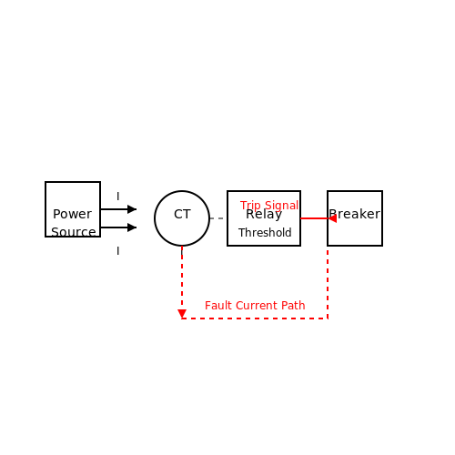
A ground fault protection system consists of three primary components:
- Current Transformer (CT): Measures the residual current by summing the line and neutral currents.
- Relay Circuit: Compares the residual current against a set threshold and initiates a trip signal if exceeded.
- Circuit Breaker: Disconnects the faulted circuit upon receiving the trip signal.
Mathematical Analysis of Fault Currents
The magnitude of ground fault current depends on the system voltage (V) and the fault impedance (Zf). For a bolted fault (Zf ≈ 0), the fault current is limited only by the system impedance (Zs):
For high-resistance grounding systems, the fault current is significantly lower:
Selective Coordination in Ground Fault Protection
Selective coordination ensures that only the protective device closest to the fault operates, minimizing system disruption. This requires careful setting of time-current curves for relays. The trip time (t) for an inverse-time relay follows:
where K and α are relay constants, I is the fault current, and Ip is the pickup current.
Practical Implementation Considerations
Ground fault protection must account for:
- Nuisance Tripping: Caused by transient currents or harmonics. Filtering algorithms in modern relays mitigate this.
- Arc Faults: Low-magnitude arcing faults may not trigger conventional protection. Arc-fault detection devices (AFDDs) supplement ground fault protection in such cases.
- High-Frequency Noise: EMI from power electronics can interfere with CT measurements. Shielded cables and proper grounding are essential.
Case Study: Industrial Ground Fault Protection
A 480V industrial distribution system with multiple motor loads experienced intermittent ground faults. Analysis revealed:
- Fault currents as low as 5A due to high-resistance grounding.
- Traditional overcurrent protection failed to detect these faults.
The solution involved installing a sensitive ground fault relay (0.5A pickup) with a 0.5s delay to prevent nuisance tripping. This reduced equipment damage by 92% over a two-year period.
Importance of Proper Grounding in Fault Conditions
Fault Current Path and Safety
Proper grounding ensures a low-impedance path for fault currents, allowing protective devices like circuit breakers and fuses to operate effectively. When a fault occurs, such as a line-to-ground short, the current must return to the source through the grounding system. The impedance of this path directly influences the magnitude of the fault current:
where Ifault is the fault current, Vsystem is the system voltage, and Ztotal is the total impedance of the fault loop (including source, conductor, and grounding resistances). A well-designed grounding system minimizes Ztotal, ensuring sufficient current flows to trip protective devices promptly.
Touch and Step Potential Hazards
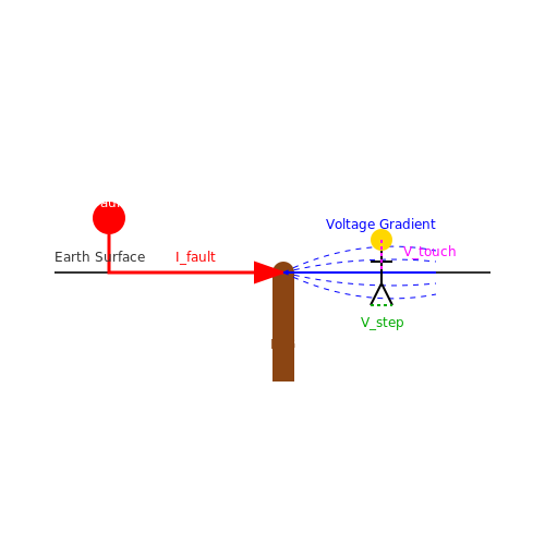
During fault conditions, improper grounding can create dangerous voltage gradients in the earth. Touch potential (voltage between a grounded object and a point 1 meter away) and step potential (voltage between two feet 1 meter apart) pose significant risks:
where IG is the ground fault current, RG is the grounding system resistance, and Kt, Ks are geometry-dependent factors. Proper grounding and equipotential bonding mitigate these hazards by ensuring rapid fault clearing and voltage gradient control.
Equipment Protection and System Stability
Grounding provides a reference point for surge arresters and transient voltage suppressors. During lightning strikes or switching surges, the grounding system must:
- Dissipate high-frequency transients without excessive voltage rise
- Maintain equipment enclosures at safe potentials
- Prevent circulating currents between interconnected systems
The transient impedance of a grounding system is frequency-dependent and can be modeled as:
where L and C represent the distributed inductance and capacitance of the grounding conductors. Proper design minimizes both DC resistance and high-frequency impedance.
Case Study: Industrial Plant Grounding Failure
A 2018 incident at a chemical processing facility demonstrated the consequences of inadequate grounding. A phase-to-ground fault in a 4.16kV motor circuit resulted in:
- Delayed fault clearing (2.3 seconds due to high ground path impedance)
- Destructive arcing at multiple junction boxes
- Corrosion-induced grounding conductor failure increased touch potential to 347V
Post-incident analysis revealed the grounding system resistance had degraded to 18Ω, far exceeding the 5Ω design specification. The event underscored the need for regular ground impedance testing and corrosion protection.
Grounding in High-Impedance Grounded Systems
Some systems intentionally use high-impedance grounding (typically through a neutral grounding resistor) to limit fault currents. The design must balance:
where RNG is the neutral grounding resistor value, VLN is line-to-neutral voltage, and IC,total is the total system capacitive charging current. This approach requires careful coordination with ground fault detection systems.
5. Grounding in Residential Wiring
Grounding in Residential Wiring
Fundamentals of Residential Grounding
Grounding in residential wiring serves two primary purposes: safety and electromagnetic interference (EMI) mitigation. The National Electrical Code (NEC) mandates grounding to prevent electric shock hazards by providing a low-impedance path for fault currents to return to the earth. In a properly grounded system, the grounding conductor connects the neutral point of the electrical service to a grounding electrode system, typically consisting of ground rods, plates, or buried conductors.
Grounding Electrode System
The grounding electrode system (GES) must comply with NEC Article 250.52, which specifies permissible electrodes:
- Metal underground water pipes (if electrically continuous).
- Concrete-encased electrodes (rebar in foundations).
- Ground rings encircling the building.
- Rod and pipe electrodes (minimum 8 ft deep).
The resistance of the grounding electrode to earth (Rg) must be low enough to ensure effective fault current dissipation. For a single ground rod, the resistance can be approximated using:
where ρ is soil resistivity (Ω·m), L is rod length (m), and d is rod diameter (m).
Equipment Grounding Conductors (EGC)
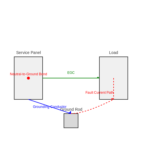
The EGC provides a return path for fault currents, ensuring circuit breakers trip promptly. NEC Table 250.122 specifies minimum conductor sizes based on overcurrent protection ratings. For example, a 20A circuit requires a 12 AWG copper EGC. The impedance (ZEGC) must satisfy:
where Vtouch is the permissible touch voltage (typically 50V) and Ifault is the prospective fault current.
Neutral-to-Ground Bonding
The NEC requires a single neutral-to-ground bond at the service entrance to prevent objectionable neutral currents on grounding paths. This bond ensures that the neutral conductor and grounding system remain at the same potential under normal operation. The bonding jumper must be sized per NEC 250.102(C), with its cross-sectional area (A) given by:
where ISC is the available short-circuit current, t is the fault duration (s), and K is a material constant (12.9 for copper).
Ground-Fault Circuit Interrupters (GFCIs)
GFCIs enhance safety by detecting leakage currents (>5mA) and interrupting the circuit within 25ms. The operating principle relies on Kirchhoff’s current law:
When Ileakage exceeds the threshold, a solenoid disconnects the circuit. NEC 210.8 mandates GFCI protection in wet locations (bathrooms, kitchens, outdoor outlets).
Practical Considerations
In older homes with knob-and-tube wiring, retrofitting grounding requires careful analysis. Solutions include:
- Installing GFCI breakers (though they don’t provide equipment grounding).
- Rewiring with NM-B cable (Romex) containing a dedicated EGC.
- Using isolated grounding for sensitive electronics to mitigate ground loops.
5.2 Industrial Grounding Practices
Industrial grounding systems must ensure personnel safety, equipment protection, and electromagnetic compatibility (EMC) in high-power environments. Unlike residential or commercial systems, industrial grounding involves complex configurations due to high fault currents, distributed equipment, and stringent regulatory requirements.
Grounding Electrode System Design
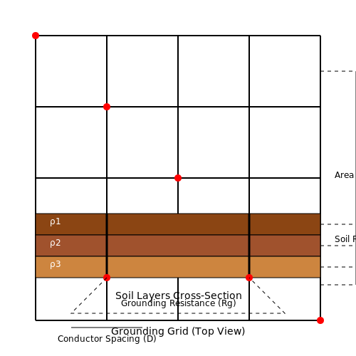
Industrial facilities typically employ a mesh grounding grid, where interconnected conductors form a low-impedance path to earth. The grid's effectiveness depends on soil resistivity (ρ), grid depth, and conductor spacing. The grounding resistance Rg of a mesh grid can be approximated using Sverak's formula:
where r is the equivalent radius of the grid conductors, and A is the grid area. For high-resistivity soils, chemical electrodes or deep-driven rods may supplement the grid.
Equipment Bonding Practices
All metallic structures—conduits, enclosures, and machinery—must be bonded to the grounding system via:
- Exothermic welding for permanent, high-current connections
- Bonding jumpers with proper ampacity ratings for flexible connections
- Parallel grounding paths to reduce inductance in high-frequency applications
Bonding impedance should not exceed 0.1 Ω per NFPA 70 and IEEE 80 standards. For rotating machinery, frame grounding must prevent circulating currents while maintaining fault protection.
Grounding for Sensitive Equipment
Industrial automation systems require separate signal reference grids (SRG) to mitigate ground loops. The SRG connects to the main grounding electrode system at a single point, creating a star topology. Shielded cabling practices include:
- 360° termination of cable shields at both ends for high-frequency noise
- Grounding shields at the source end only for low-frequency analog signals
- Isolated ground (IG) receptacles for PLCs and measurement devices
Lightning Protection Integration
Industrial lightning protection systems (LPS) must coordinate with equipment grounding through:
- Down conductors spaced ≤25 m apart per IEC 62305
- Surge protective devices (SPDs) with proper let-through voltage ratings
- Equipotential bonding of all metallic services within 3 m of ground level
The lightning protection earth termination must interconnect with the main grounding system, with a combined resistance typically <10 Ω.
Ground Fault Protection
High-resistance grounding (HRG) systems limit fault currents to <10 A while maintaining system continuity. The grounding resistor value Rn is calculated based on system charging current Ic:
where VLL is the line-to-line voltage. Ground fault relays must detect faults while remaining stable during transient conditions.
Periodic Testing and Maintenance
Industrial grounding systems require regular verification through:
- Fall-of-potential tests for electrode resistance
- Clamp-on measurements for continuity
- Thermographic inspections of connections
- Soil resistivity measurements every 5 years
Test results should be compared against baseline measurements to identify degradation trends.
5.3 Compliance with NEC and IEC Standards
Grounding and bonding practices must adhere to stringent regulatory frameworks to ensure safety and operational reliability. The National Electrical Code (NEC) and International Electrotechnical Commission (IEC) standards provide the foundational guidelines, though their approaches differ in scope and enforcement.
NEC Requirements for Grounding and Bonding
The NEC (NFPA 70) mandates grounding and bonding to mitigate electrical hazards, primarily focusing on:
- Equipment Grounding Conductors (EGCs): NEC Article 250.118 specifies acceptable EGC types, including copper, aluminum, or steel, with minimum cross-sectional areas based on circuit ampacity.
- Bonding Jumpers: Article 250.102(C) requires bonding jumpers to maintain equipotential planes, with sizing determined by:
where Ifault is the prospective fault current, t is the fault duration, and K is a material constant (e.g., 722 for copper).
- Ground-Fault Protection: NEC 230.95 enforces ground-fault interrupters for systems >150V to ground with currents ≥1000A.
IEC Standards (IEC 60364 Series)
IEC standards adopt a risk-based approach, emphasizing:
- TT, TN, and IT Systems: IEC 60364-4-41 defines earthing arrangements, requiring fault loop impedance Zs to satisfy:
where U0 is nominal voltage and Ia is current causing protective device operation within specified time.
- Equipotential Bonding: IEC 60364-4-42 mandates bonding of extraneous conductive parts, with conductor cross-sections ≥6mm² for copper or equivalent conductance for other materials.
Key Differences Between NEC and IEC
| Criterion | NEC | IEC |
|---|---|---|
| System Classification | Focuses on equipment grounding | Classifies by earthing arrangement (TT/TN/IT) |
| Fault Current Calculation | Uses empirical tables | Requires explicit loop impedance verification |
| Enforcement | Legally binding in U.S. jurisdictions | Adopted voluntarily unless codified nationally |
Practical Implementation Challenges
Harmonizing NEC and IEC requirements is critical for multinational facilities. For example, data centers often implement:
- Hybrid Grounding: TN-S systems (per IEC) with supplemental equipotential grids meeting NEC 250.52(A)(2) for concrete-encased electrodes.
- Transient Protection: Lightning protection systems must comply with both NEC Article 250 and IEC 62305, requiring coordination between grounding electrode systems and bonding conductors.
Case studies show that improper cross-standard compliance increases touch potential risks by up to 40% during fault conditions, underscoring the need for rigorous design validation.
6. Essential Books and Publications
6.1 Essential Books and Publications
- PDF Practical Earthing, Bonding, Lightning and Surge Protection - IDC-Online — 2 Grounding of power supply systems and neutrals 16 2.1 Introduction 16 2.2 Ungrounded systems 18 2.3 Solidly grounded systems 21 2.4 Impedance grounding using neutral reactor 21 2.5 Resonant grounding using neutral reactor 22 2.6 Impedance grounding through neutral resistance 23 2.7 Point of grounding 24 2.8 Other challenges 27
- Grounds for Grounding: A Handbook from Circuits to Systems, 2nd Edition — GROUNDS FOR GROUNDING Gain a comprehensive understanding of all aspects of grounding theory and application in this new, expanded edition Grounding design and installation are crucial to ensure the safety and performance of any electrical or electronic system irrespective of size. Successful grounding design requires a thorough familiarity with theory combined with practical experience with ...
- Grounds for Grounding: A Circuit to System Handbook | Wiley — GROUNDS FOR GROUNDING. The first book to cover grounding from the circuit to system and across the entire spectrum of applications. Grounds for Grounding provides a complete and thorough approach to the subject of designing electrical and electronic circuits and systems, blending theory and practice to demonstrate how a few basic rules can be applied across a broad range of applications.
- PDF GROUNDS FOR GROUNDING A Circuit-to-System Handbook — 4.7.1. External Signal and Safety Grounding Interconnects 297 between Enclosures 4.7.2. Equipment DC Power, Signal, and Safety Grounding 298 4.7.3. Power Distribution Grounding Schemes in Integrated 301 Clustered Systems 4.7.4. Grounding of Equipment Enclosure Shield 305 4.8. Rack and Cabinet Subsystem Grounding Architecture 308 4.8.1.
- Grounds for Grounding A Handbook from Circuits to Systems — Buy Grounds for Grounding A Handbook from Circuits to Systems - 9781119770930 by Joffe, Elya B. for as low as $132.85. ... Grounding design and installation are crucial to ensure the safety and performance of any electrical or electronic system irrespective of size. Successful grounding design requires a thorough familiarity with theory ...
- PDF Grounding - ANSI Webstore — grounding conductor needs to be measured while evaluating systems with both AC equipment ground and Auxiliary ground. ANSI/ESD S6.1-2014 is a revision of ANSI/ESD S6.1-2009 and was approved on September 24, 2013. At the time ANSI/ESD S6.1-2014 was prepared, the 6.0 Grounding Subcommittee had the following members: David E. Swenson, Chairperson
- Grounds for Grounding: A Circuit to System Handbook — GROUNDS FOR GROUNDING. The first book to cover grounding from the circuit to system and across the entire spectrum of applications. Grounds for Grounding provides a complete and thorough approach to the subject of designing electrical and electronic circuits and systems, blending theory and practice to demonstrate how a few basic rules can be applied across a broad range of applications.
- Grounding, Bonding, Shielding Handbook - studylib.net — MIL-HDBK-419A: Grounding, bonding, and shielding theory for electronic equipment and facilities. Covers safety, interference, and EMP protection.
- PDF GROUNDING AND SHIELDING - download.e-bookshelf.de — Wiley also publishes its books in a variety of electronic formats. Some content that appears in ... The Defi nition of Voltage 6 1.6. Equipotential Surfaces 8 1.7. The Electric Force Field between Two Conducting Plates 9 ... Utility Power and Facility Grounding 49. 3.1. Introduction 49 3.2. History 49 3.3. Semantics 50 3.4. The Earth as a ...
- ANSI-ESD S6.1-2009 Grounding | PDF | Electrostatic Discharge ... — ANSI-ESD S6.1-2009 Grounding - Free download as PDF File (.pdf), Text File (.txt) or read online for free. This standard applies to bonding and grounding for the prevention of ESD in an EPA
6.2 Online Resources and Tutorials
- PDF Practical Grounding/Earthing, Shielding, EMC/EMI and ... - IDC-Online — 5 Grounding 50 5.1 Introduction 50 5.2 Earth and safety ground 51 5.3 Grounding and frequency 53 5.4 Ground loops 54 5.5 Ground impedance 55 5.6 Ground topologies 55 5.7 Guidelines for grounding 57 6 Cables and connectors 60 6.1 Introduction 60 6.2 Cables in context 61 6.3 Cable parameters and implication 62
- PDF Practical Earthing, Bonding, Lightning and Surge Protection - IDC-Online — 1.2 Basics of grounding 2 1.3 Bonding 4 1.4 Lightning and its effect on electrical systems 5 1.5 Static charges and need for bonding 5 1.6 Ground electrodes and factors affecting their efficacy 7 1.7 Noise in signaling circuits and protective measures such as shielding 10 1.8 Surge Protection of electronic equipment 12
- PDF MIL-HDBK-419A Grounding, Bonding, and Shielding for Electronic ... — 3. This document provides basic and application information on grounding, bonding, and shielding practices recommended for electronic equipment.It will provide valuable information and guidance to personnel concerned with the preparation of specifications and the procurement of electrical and electronic
- PDF GROUNDS FOR GROUNDING A Circuit-to-System Handbook — 4.7.1. External Signal and Safety Grounding Interconnects 297 between Enclosures 4.7.2. Equipment DC Power, Signal, and Safety Grounding 298 4.7.3. Power Distribution Grounding Schemes in Integrated 301 Clustered Systems 4.7.4. Grounding of Equipment Enclosure Shield 305 4.8. Rack and Cabinet Subsystem Grounding Architecture 308 4.8.1.
- Grounding Bonding Shielding - Vol1 | PDF | Alternating Current - Scribd — This document provides a summary of key information from the Military Handbook MIL-HDBK-419A, which establishes guidelines for effective grounding, bonding, and shielding practices for electronic equipment and facilities. The handbook discusses the objectives and requirements for facility ground systems, including considerations for lightning protection, fault protection, and noise reduction ...
- PDF Practical Grounding, Bonding, Shielding and Surge — down into grounding, shielding and surge protection for both power and electronics systems. Grounding and surge protection for Telecommunications and IT systems are examined in detail. Finally, the impact of lightning is examined and simple techniques for minimizing its impact are described.
- PDF Grounding Techniques for Tactical Equipment and Systems — TC 6-02.6 provides a significant resource to Army trainers and educators. Commanders, staffs, and subordinates ensure their decisions and actions comply with applicable Unites States, ... This bonding holds all conductive parts at the same voltage to prevent shock hazards. Also it provides short-circuit path to clear circuit breakers in the ...
- PDF Telecommunication Grounding & Bonding - BICSI — Set up - Components of grounding & Bonding System ISO/IEC Referenced. TIA 607-B & ISO/IEC 30129. Maximum TMGBB (PBB) to TGBB (SBB) Length (L) meters (feet) ... (Military Handbook Grounding, Bonding & Shielding for Electronic. Equipment & Facilities) MIL-UFC-3-580-01:2016 (Military Unified Facility Command Telecommunications.
- PDF Testing and Evaluation of Grounding Systems: The Revision of the IEEE ... — Grounding and Bonding is Fundamental for a Safe and Reliable Power System. IEEE Industry Applications Society - Atlanta Chapter January 19, 2010 Meeting 3 Grounding, Bonding and Power Quality "Recent studies indicate that as much as 80% of all failures of sensitive electronic equipment attributed to poor power quality may result from
- Grounding, Bonding, Shielding Handbook - studylib.net — MIL-HDBK-419A: Grounding, bonding, and shielding theory for electronic equipment and facilities. Covers safety, interference, and EMP protection.
6.3 Industry Standards and Regulations
- PDF Lightning and Surge Protection, Grounding, Bonding, and Shielding ... — Further, the requirements herein are coordinated with industry standards, and in some cases exceed industry standards where necessary to meet the FAA missions. 3. The use of "shall" or verbs such as "provide," "construct," "weld," or "connect" indicates ... 4.7 Grounding and Bonding for NAS Electronic Equipment Areas ...
- (PDF) Recommended Practice for System Grounding of Industrial and ... — IEEE Standards documents (standards, recommended practices, and guides), ... IEEE Standards are documents developed through scientific, academic, and industry-based technical working groups. Volunteers in IEEE working groups are not necessarily members of the Institute and participate without compensation from IEEE. ... grounding electronic ...
- PDF By Order of The Air Force Manual 32-1065 Secretary of The Air ... - Af — 1.4.10. Assist DRUs and Air Force installations with inspecting grounding and bonding systems and with troubleshooting electrical issues suspected to stem from grounding and bonding issues and discrepancies. 1.4.11. Assists Air Force Safety Center (AFSEC) and Inspector General (IG) personnel with
- PDF Improved Bonding and Grounding Methods for Electrical / Electronic ... — Bonding and grounding of electrical equipment installed aboard U. S. Navy Ships must be accomplished to the requirements of MIL-STD-1310, Standard Practice for Shipboard Bonding, Grounding, and Other Techniques for Electromagnetic Compatibility and Safety. These requirements are well established as an effective quality
- PDF Neca607 11 111711 - Bicsi — bonding and grounding systems within a commercial building (see figure 1). This standard is intended to enhance the planning, specification and layout of an effective telecommunications bonding and grounding system. Additionally, this standard specifies installa- tion requirements for components of the telecom-
- PDF KSC-STD-E-0022, Change 2 February 5, 2019 BONDING, GROUNDING ... - NASA — used in conjunction with the KSC facility standard KSC-STD-E-0012, Facility Grounding and Lightning Protection, Standard for, which provides requirements for facility grounding, bonding and lightning designs. These facility systems provide connections and paths to earth ground for
- PDF Bonding, Grounding, Shielding, Electromagnetic Interference, Lightning ... — This standard provides design and testing requirements for bonding, grounding, shielding, electromagnetic interference (EMI), lightning protection, electrostatic discharge (ESD) protection, transient protection, and surge suppression for electrical and electronic ground systems (GS) to be used at the Kennedy Space Center (KSC).
- PDF Grounding - ANSI Webstore — an electronic retrieval system or otherwise, without the prior ... standard also specifies the criteria for establishing ESD bonding for the protection of ESD susceptible items in field service or other remote operations. 1.2 Scope This standard applies to bonding and grounding for the prevention of ESD in an EPA. The procedures, materials, and ...
- PDF Shipboard Bonding, Grounding, and Other Techniques for Electromagnetic ... — inch-pound . mil-std-1310h(navy) 17 september 2009 . superseding . mil-std-1310g(navy) 28 june 1996 . department of defense standard practice . shipboard bonding, grounding, and other
- PDF Testing and Evaluation of Grounding Systems: The Revision of the IEEE ... — IEEE Industry Applications Society - Atlanta Chapter January 19, 2010 Meeting 3 Grounding, Bonding and Power Quality "Recent studies indicate that as much as 80% of all failures of sensitive electronic equipment attributed to poor power quality may result from inadequate electrical grounding or wiring on the customer's premises or