Chebyshev and Elliptic Designs
1. Overview of Filter Types
1.1 Overview of Filter Types
In the realm of signal processing, filters play an indispensable role, serving a myriad of applications such as audio processing, telecommunications, and instrumentation. Among the various filter designs, Chebyshev and Elliptic filters stand out for their distinct performance characteristics and response profiles. To fully appreciate their relevance, we first need to explore the different types of filters commonly used in electrical engineering.Understanding Filter Types
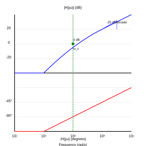
Filters can generally be classified into several categories based on their frequency responses, implementation techniques, and their phase characteristics. The most fundamental classifications include:- Low-Pass Filters: These filters allow signals with a frequency lower than a certain cutoff frequency to pass through while attenuating frequencies above this threshold. They are crucial in audio applications to remove high-frequency noise.
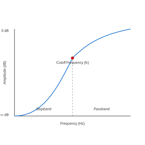
- High-Pass Filters: In contrast, high-pass filters permit signals with frequencies above a certain cutoff to pass and attenuate lower frequencies. This can be beneficial in applications such as voice recognition systems.
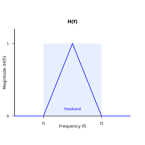
- Band-Pass Filters: These filters enable a specific range of frequencies to pass through while blocking frequencies outside this band. They've found extensive use in communication systems, where they isolate the desired signal from unwanted noise.
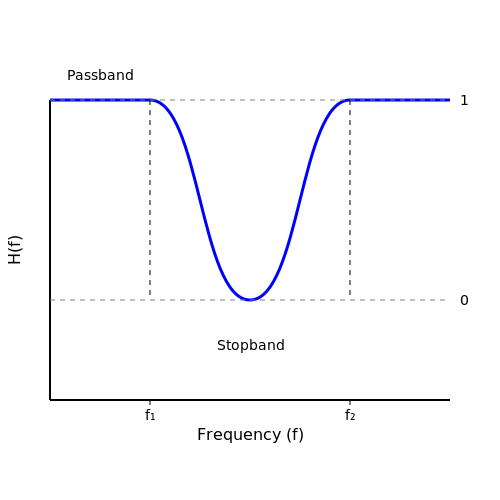
- Band-Stop Filters: Also known as notch filters, these eliminate a specific band of frequencies while allowing others to pass. They're often used in audio processing to suppress feedback frequencies.
Chebyshev Filters
Chebyshev filters are notable for their sharp roll-off characteristics and are primarily defined by their passband ripple, which allows for steeper attenuation beyond the cutoff frequency. These filters feature either equal ripple in the passband (Type I) or the stopband (Type II). The configuration has significant implications for practical applications: - Type I Chebyshev Filters: These have ripple only in the passband, allowing for a more rapid transition from pass to stopband. The ripple affects the signal's amplitude, which can be a double-edged sword depending on the application. - Type II Chebyshev Filters: Conversely, these filters present ripple in the stopband while maintaining a monotonic response in the passband, thereby protecting critically important signal components from distortion. The frequency response of a Chebyshev filter can be mathematically derived using the Chebyshev polynomial, denoting the following transfer function:Elliptic Filters
Elliptic filters, or Cauer filters, extend the concept of filter design by allowing ripple in both the passband and the stopband, enabling the sharpest transition between these two regions. This makes them particularly suitable for applications where space and size are constraints, such as RF communications and signal processing in compact devices. The defining feature of elliptic filters is their equalized ripple magnitude across both the passband and stopband, which enables a steeper roll-off. The transfer function for an elliptic filter can be expressed as:Practical Relevance
In practical implementations, the choice between a Chebyshev and an Elliptic filter may depend on the specific application requirements. For instance, when high fidelity is paramount, Chebyshev filters are often chosen due to their excellent performance in terms of ripple characteristics. Conversely, when minimizing the physical size of the circuit is critical, elliptic filters may be preferred for their compact design and steep roll-off. Understanding the unique attributes of each filter type allows engineers and researchers to make informed design decisions suited to the specific demands of their applications. The ongoing evolution and integration of these filters into advanced systems continue to reveal new pathways for innovation and improvement in the field of electronics.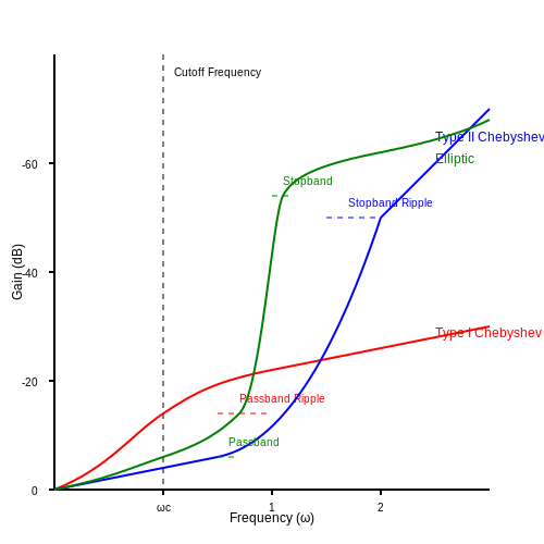
1.2 Standard Filter Responses
The design of filters is a critical aspect of signal processing in various engineering applications, including audio engineering, telecommunications, and electronic circuit design. Two prominent classes of filters are Chebyshev and Elliptic filters, each known for their distinctive characteristics in response behavior. This section delves into the standard filter responses of these two designs, elucidating their unique traits and practical implications.
Understanding Filter Responses
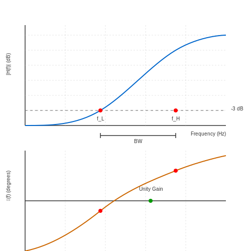
To comprehend the differences between Chebyshev and Elliptic filters, we must first recap what filter responses entail. A filter response describes how a filter modifies the amplitude and phase of input signals across a range of frequencies. The primary types of filter responses include:
- Low-pass filters: These allow signals with a frequency lower than a certain cutoff frequency to pass through while attenuating frequencies higher than the cutoff.
- High-pass filters: As opposed to low-pass filters, high-pass filters permit signals with a frequency above a certain cutoff frequency to pass and attenuate lower frequencies.
- Band-pass filters: These only allow a certain range, or "band," of frequencies to pass through, rejecting both lower and higher frequencies.
- Band-stop filters: Also known as notch filters, these eliminate signals within a certain frequency range while allowing others to pass.
Chebyshev Filter Responses
Chebyshev filters are distinguished by their rippled frequency response in the passband, which is a trade-off for a steeper roll-off compared to Butterworth filters. The key feature of a Chebyshev filter is its ability to achieve a sharper transition from passband to stopband. The mathematical representation of the frequency response H(s) for a Chebyshev filter can be articulated as follows:
Here, ω is the frequency, ωc is the cutoff frequency, Tn is the Chebyshev polynomial of the nth order, and ε denotes the ripple factor, which establishes the allowable ripple in the passband.
The implications of this ripple are significant in applications requiring precision in specific frequency ranges, such as in audio systems and telecommunications. Engineers often select Chebyshev filters when a sharp cutoff is paramount, but slight amplitude deviations in the passband are acceptable.
Elliptic Filter Responses
Elliptic filters, also known as Cauer filters, extend the principles of Chebyshev filters further by allowing ripple both in the passband and stopband. This dual-ripple approach facilitates the steepest possible roll-off for given filter order specifications. The frequency response for an Elliptic filter can be represented similarly, incorporating parameters for both passband and stopband ripple:
In this equation, K is related to the gain factor, εp is the passband ripple, and En stands for the elliptic functions corresponding to filter order n and frequency. The inclusion of a stopband ripple factor allows for greater flexibility in the design, which can result in a more effective application in situations such as data communications where both desired and undesired frequency components need precise management.
Practical Applications
The practical relevance of these filter designs cannot be overstated. Chebyshev filters are employed extensively in applications where speed and sharpness of cutoff are required, such as in RF communication systems. Conversely, the unique characteristics of Elliptic filters make them suitable for high-speed data applications, where bandwidth conservation is crucial.
Ultimately, both filter responses showcase the delicate balance between design complexity and performance, providing engineers with powerful tools to sculpt signals according to the specific needs of their applications.
1.3 Importance of Chebyshev and Elliptic Filters
In the realm of signal processing, Chebyshev and Elliptic filters hold a preeminent position due to their distinct characteristics that address specific filtering requirements in advanced applications. This section will elucidate the significance of these filter designs, their advantages, and real-world applications that demonstrate their relevance.
Understanding the Fundamentals
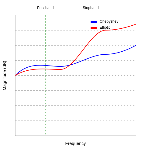
Before delving into their importance, it is crucial to recap their foundational concepts. Chebyshev filters are characterized by their ability to provide a steeper roll-off around the cutoff frequency compared to Butterworth filters, sacrificing a bit of ripple in the passband for enhanced filter performance. Meanwhile, Elliptic filters exemplify an even more aggressive approach, allowing ripple in both the passband and the stopband, which leads to the steepest roll-off achievable among all filter types. Such performance enhancements are mediated through their unique transfer function designs, which leverage elliptic integral functions.
Advantages Over Other Filter Types
The primary advantage of utilizing Chebyshev and Elliptic filters lies in their optimized performance metrics:
- Steeper Roll-Off: Chebyshev and Elliptic filters achieve a sharper transition from the passband to the stopband, effectively reducing the width of the transition band. This is particularly beneficial in applications where adjacent channel interference is a concern.
- Size and Complexity: Due to their efficient frequency response, these filters often require fewer components compared to other types of filters achieving similar performance, which can significantly reduce the overall size and complexity of electronic systems.
- Customizability: The design parameters of Chebyshev and Elliptic filters can be finely tuned, allowing engineers to create filters that precisely match the specific frequency response required by the application.
Real-World Applications
Chebyshev and Elliptic filters are relentlessly utilized in several critical domains:
- Telecommunications: These filters are integral in modems and other transmission systems, efficiently isolating signal bandwidths and minimizing crosstalk between channels.
- Audio Signal Processing: In audio systems, Chebyshev filters can shape sound quality by effectively removing unwanted frequency components without significantly altering the desired audio signal.
- Medical Imaging: In MRI and ultrasound technologies, these filters help in improving image clarity by suppressing noise and enhancing signal fidelity.
Conclusion
In summary, the significance of Chebyshev and Elliptic filters is underscored by their ability to deliver exceptional performance metrics tailored to specific applications. As electronic systems continue to evolve with increasing demands on signal integrity and processing speed, the utilization of these sophisticated filtering solutions will undoubtedly remain a cornerstone of modern engineering practices.
2. Definition and Characteristics
Chebyshev and Elliptic Designs
2.1 Definition and Characteristics
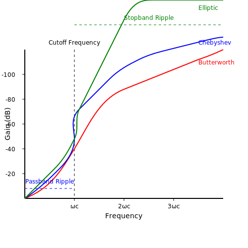
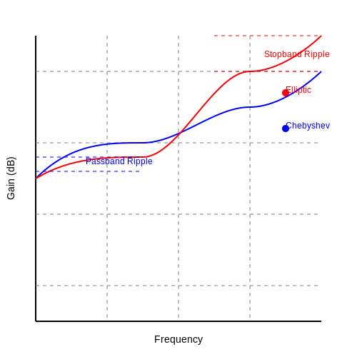
In the realm of filter design, the Chebyshev and Elliptic filters are two fundamental approaches that offer unique characteristics tailored to specific application requirements. The choice between these designs hinges on a complex balance between the desired frequency response, insertion loss, ripple, and transition bandwidth. The Chebyshev filter, named after the Russian mathematician Pafnuty Chebyshev, is defined by its ability to achieve a steeper roll-off than Butterworth filters by allowing ripple in the passband. This ripple is measured in decibels (dB) and indicates variation in amplitude response across the passband. The mathematical formulation of the Chebyshev polynomial plays a critical role in determining the transfer function of the filter, given by: $$ H(s) = \frac{1}{\sqrt{1 + \epsilon^2 T_n^2\left(\frac{s}{\omega_c}\right)}} $$ where \( T_n \) is the Chebyshev polynomial of order \( n \), \( \epsilon \) is the ripple factor that dictates the sensitivity of the ripples, and \( \omega_c \) is the cutoff frequency. In contrast, the Elliptic filter, also referred to as Cauer filters, stands out due to its ability to achieve an even sharper roll-off than Chebyshev filters while exhibiting both passband and stopband ripple. The mathematical description of an elliptic filter is more complex, rooted in the Jacobi elliptic functions and characterized by its equi-ripple performance. The transfer function of an elliptic filter can be succinctly written as: $$ H(s) = \frac{K}{K - \frac{1}{K} \left( \frac{s}{j\omega_0} \right) ^{n/2}} $$ In this equation, \( K \) is a constant determined by the ripple levels in each band, and \( \omega_0 \) is the resonant frequency. This intricate formulation highlights the capacity of elliptic filters to strike an optimal balance between minimization of the passband ripple and control over the stopband characteristics. When comparing their characteristics:- Passband Ripple: Chebyshev filters allow for a specific level of ripple, whereas elliptic filters allow ripple in both passband and stopband, leading to more efficient designs.
- Stopband Characteristics: Elliptic filters excel in minimizing stopband waveforms with steeper attenuation slopes.
- Filter Order: For a similar performance, the elliptic filter can achieve this with a lower order than the Chebyshev, substantially saving on component count and board space.
- Real-World Applications: Chebyshev and elliptic filters are extensively used in communication systems, analog signal processing, and audio signal processing, where precise frequency selection is paramount.
2.2 Design Equations
In this section, we delve into the fundamental design equations that govern Chebyshev and Elliptic filters. Understanding these equations is critical for engineers and researchers aiming to implement filtering solutions that meet specific performance criteria, such as ripple and bandwidth. The Chebyshev filter, known for its excellent passband characteristics, employs a specific polynomial known as the Chebyshev polynomial. The key to its design is the epsilon (\(\epsilon\)), which quantifies the ripple in the passband. This ripple is crucial for determining the filter's sharpness. The Chebyshev polynomials can be expressed mathematically as follows: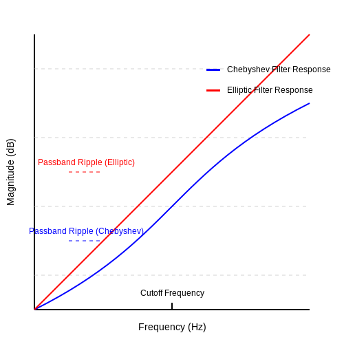
2.3 Passband Ripple and Its Effects
The concept of passband ripple is a critical aspect of filter design, particularly within the realms of Chebyshev and elliptic filters. Passband ripple refers to the variations in amplitude response within the passband of a filter. Understanding its implications not only deepens our comprehension of filter behavior but also informs practical applications in signal processing and communication systems.Understanding Passband Ripple
In essence, passband ripple is an inherent characteristic of certain filter designs where the magnitude of the output signal oscillates within the designated passband frequencies—this oscillation is expressed in decibels (dB). For Chebyshev filters, this ripple occurs uniformly across the passband, which is a trade-off for achieving a sharper cutoff compared to other types, such as Butterworth filters, which are ripple-free but more gradual in rolloff.Mathematical Representation
Let's delve into the mathematical formulation of passband ripple. For a Chebyshev filter, the ripple, often denoted as \( \epsilon \), can be mathematically defined based on the ripple factor \( A_p \) (the maximum passband gain). The ripple in the dB can be calculated by:Effects on Filter Performance
The effects of passband ripple are significant for filter performance, especially in applications demanding high fidelity. Some notable impacts include: 1. Signal Distortion: The oscillation can lead to unexpected signal variations, potentially introducing harmonics that were not present in the original signal, affecting clarity. 2. Increased Sensitivity to Variations: Filters with sharper roll-offs and considerable ripple can make the system more sensitive to frequency shifts and alterations in signal amplitude. 3. Trade-off Considerations: While setup specifications may require tight cutoff frequencies, engineers must balance the desire for minimal ripple with other parameters, like insertion losses and phase response, which may be adversely affected.Practical Applications
The practical implications of passband ripple extend to numerous fields including telecommunications, audio processing, and instrumentation. In these applications, engineers often choose elliptic filters when minimal ripple within the passband and rapid roll-off are required, as they offer both benefits but at a cost of complexity in design. For instance, in radio frequency applications, having a defined ripple might allow for the selective amplification of desired signals while efficiently attenuating others. In audio applications, however, excessive ripple can lead to noticeable distortion, which necessitates a carefully considered design process. In modern applications of digital signal processing (DSP), the advent of adaptive filtering techniques has offered solutions to minimize the effects of passband ripple, using real-time data to adjust the filter coefficients dynamically, ensuring optimal filter performance under varying conditions. Thus, understanding passband ripple enables engineers and physicists to make informed decisions in filter design, thereby enhancing the overall performance and reliability of various electronic systems where purity of signal is paramount.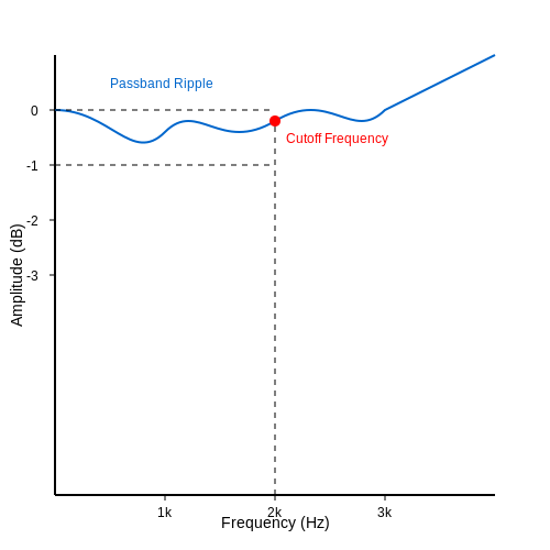
2.4 Applications of Chebyshev Filters
Chebyshev filters are renowned for their steep roll-off characteristics and their ability to achieve high selectivity. This subsection delves into the myriad applications of Chebyshev filters across various fields, highlighting their fundamental importance in both theoretical and practical contexts.
Signal Processing
One of the primary applications of Chebyshev filters lies in the domain of signal processing. Their frequency response is designed to provide a specific ripple within the passband, allowing engineers to tailor the filter characteristics to meet stringent requirements. This feature is particularly advantageous in applications such as:
- Data Communication: In telecommunications, Chebyshev filters are utilized for noise reduction and signal shaping, ensuring that transmitted information maintains integrity over long distances.
- Audio Processing: In audio engineering, these filters enable precise manipulation of sound frequencies, allowing for enhanced audio clarity and fidelity in mixing consoles and sound reinforcement systems.
Image Processing
Chebyshev filters are also employed in the realm of image processing. Their ability to suppress unwanted frequencies can effectively minimize noise while preserving essential image details. Specific applications include:
- Edge Detection: By selectively filtering higher frequencies, Chebyshev filters enhance edges within images, aiding in more accurate object detection and recognition.
- Compression Techniques: Used in image compression algorithms, Chebyshev filters help to reduce data bandwidth by allowing only the most significant frequency components to pass through, thus optimizing file sizes without substantial quality loss.
Control Systems
In control systems design, Chebyshev filters are invaluable for managing system stability and performance. They are often used in:
- PID Controllers: By integrating Chebyshev filters within a PID controller, engineers can effectively shape the loop response, managing overshoot and improving transient response.
- Sensing Applications: These filters filter out high-frequency noise from sensor signals, providing more accurate readings that are critical for system feedback and control processes.
Biomedical Applications
In the biomedical field, Chebyshev filters have emerged as vital components in various diagnostic and monitoring systems:
- Electrocardiograms (ECGs): Chebyshev filters are frequently used in ECG machines to filter out artifacts and noise, ensuring that the heart's electrical activity is monitored accurately.
- Medical Imaging: The filters help enhance images sourced from modalities like MRI and ultrasound, allowing for more precise diagnostics.
Aerospace and Defense
The aerospace and defense sectors also leverage Chebyshev filters for several critical applications:
- Radar Systems: The steep roll-off qualities of Chebyshev filters make them ideal for clutter rejection in radar systems, significantly improving target detection capabilities.
- Communication Equipment: In satellite communications, Chebyshev filters are utilized to improve signal clarity by minimizing cross-talk between channels, which is essential for reliable data transmission.
In conclusion, the applications of Chebyshev filters are diverse and profound, ranging from enhancing audio clarity to improving the accuracy of biomedical instruments. Their unique characteristics allow engineers and researchers to address specific challenges across various disciplines, making them a fundamental tool in both theory and application.
3. Overview of Elliptic Filters
3.1 Overview of Elliptic Filters
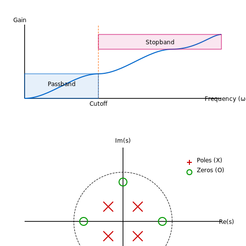
In the realm of filter design, elliptic filters, also known as Cisaclian filters, represent a compelling solution due to their unique ability to offer a compromise between selectivity and passband ripple. These filters are particularly notable for their elliptical shape in the passband, which facilitates a smoother transition between the passband and stopband. The attributes of elliptic filters make them particularly suitable for applications where size and performance are critical, such as in RF and communication systems, where bandwidth efficiency is paramount.Principle of Operation
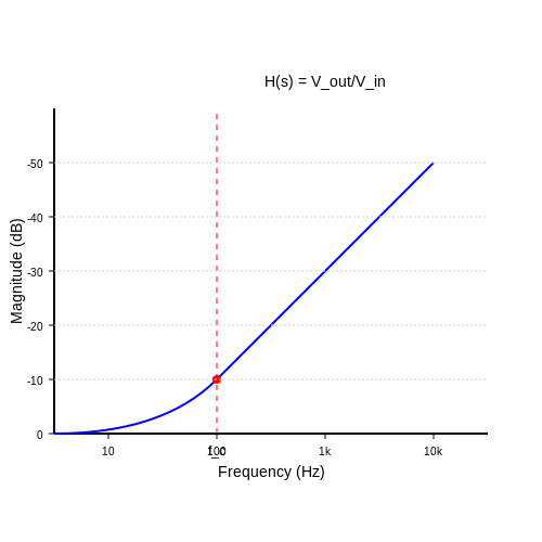
Elliptic filters leverage a combination of poles and zeros placed strategically on the complex frequency plane. This placement results in a frequency response that exhibits a fixed amount of ripple within the passband and a relatively faster roll-off characteristic compared to Butterworth and Chebyshev filters. The core of their operation can be understood through parameterized frequency transformations. To derive the transfer function for an elliptic filter, we begin with the standard differential equation governing linear time-invariant (LTI) systems. The voltage transfer function \( H(s) \) can be expressed as: $$ H(s) = \frac{V_{out}(s)}{V_{in}(s)} = \frac{b_0 + b_1 s + b_2 s^2 + ... + b_n s^n}{a_0 + a_1 s + a_2 s^2 + ... + a_m s^m} $$ where \( b_i \) and \( a_i \) represent the filter coefficients, \( n \) and \( m \) are the orders of the numerator and denominator polynomial, respectively. The elliptic filter's coefficients are determined based on elliptic integrals, particularly the first kind, \( K(k) \), and the second kind, \( E(k) \), where \( k \) is the elliptic modulus.Key Characteristics
One of the defining features of elliptic filters is their achievable sharp cutoff capabilities along with a specified level of ripple in both the passband and stopband. This property can be quantified using the normalized cutoff frequency, which is a function of the filter's order \( N \) and ripple factor \( r \): $$ f_c = \frac{1}{\pi} K(k) $$ where \( K(k) \) is derived from the elliptic integral, signifying the relationship between the ripple and the filter's bandwidth. The sharper transition results in an increased selectivity, making elliptical filters indispensable in frequency-sensitive applications, such as cellular and satellite communications.Real-World Applications
The practical implications of elliptic filters are vast:- RF and Communication Systems: Their bandwidth efficiency makes elliptic filters ideal for mobile communication systems, where multiple channels must coexist in close proximity.
- Audio Processing: In professional audio equipment, the precise control over frequency response allows for enhanced sound quality and dynamic range.
- Sensors and Instrumentation: The high precision required in measurement equipment often relies on the performance of elliptic filters for signal conditioning.
3.2 Key Design Parameters
In the realm of filter design, Chebyshev and elliptic filters offer distinct attributes suitable for various applications. Understanding the key design parameters for these filters is crucial to effectively utilize their characteristics in real-world scenarios. These parameters dictate not only the performance of the filter but also influence its implementation in practical systems.
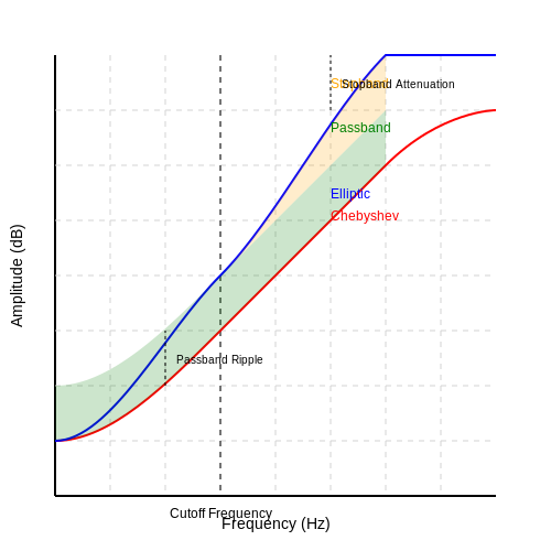
Passband Ripple
One of the most significant parameters for Chebyshev filters is the passband ripple. This parameter quantifies the allowed variation in the amplitude response of the filter within the designated passband. For Chebyshev filters, this is essential because it results in a steeper roll-off compared to Butterworth filters for a given order.
Mathematically, the passband ripple, denoted as ρ, is given in decibels (dB) as:
where ε (epsilon) is the ripple factor, which characterizes the maximum deviation in the passband. The design implication is profound; lowering the ripple factor enhances flatness in the passband but results in reduced steepness in the roll-off. This often necessitates trade-offs depending on the application requirements.
Stopband Attenuation
Alongside passband ripple, the stopband attenuation is another crucial design parameter that defines how effectively the filter suppresses unwanted frequencies beyond the cutoff frequency. Chebyshev filters are designed to achieve a specified stopband attenuation, which can be set according to the needs of a specific application. The attenuation can be calculated using the following equation:
where \( A_s \) is the stopband attenuation, \( H(j\omega_s) \) is the filter's transfer function evaluated at the stopband frequency \( \omega_s \). A higher value of stopband attenuation results in better rejection of unwanted signals but may lead to increased complexity in filter design.
Cutoff Frequency
The cutoff frequency plays a pivotal role in the definition of both Chebyshev and elliptic filters. This frequency determines the boundary between the passband and the stopband. Engineers typically define this frequency to optimize the filter’s operational bandwidth, considering the specific frequencies of interest in tangible applications such as communication systems or audio processing.
Order of the Filter
The order of the filter directly relates to the number of reactive components utilized in the design. Higher order filters exhibit a steeper roll-off, which can be robust against noise but increases the complexity and cost of implementation. For Chebyshev filters, the order \( n \) can be determined from the desired specifications using the following approximation:
In this equation, \( A_p \) and \( A_s \) represent the passband and stopband attenuations, respectively, while \( f_p \) and \( f_s \) denote the corresponding cutoff frequencies. This relationship provides essential insight for filter design, as it helps in striking a balance between performance and feasibility.
Implementation Considerations
Finally, when designing Chebyshev or elliptic filters, practical considerations such as component tolerances, temperature stability, and power handling must be accounted for. These factors can significantly impact the filter’s performance in real-world applications. Engineers should assess these elements holistically to ensure the filter operates effectively under diverse conditions, ensuring reliability in critical applications such as telecommunications and audio signal processing.
Real-World Applications
Understanding these parameters facilitates the effective design of filters that meet stringent requirements in practical applications. For instance, high-precision communication systems utilize elliptic filters due to their excellent selectivity and minimal phase distortion, while Chebyshev filters are frequently employed in audio equipment where a controlled ripple is acceptable.
3.3 Advantages Over Other Filter Types
In the landscape of signal processing, the Chebyshev and Elliptic filter designs stand out due to their unique advantages that elevate them above other filter types like Butterworth or Bessel filters. Understanding these advantages requires a multifaceted exploration of their properties and real-world applications.Superior Frequency Selectivity
One of the standout features of Chebyshev and Elliptic filters is their ability to achieve a higher roll-off rate compared to other types of filters, such as Butterworth filters, which prioritize a maximally flat response but do not excel in selectivity. The roll-off rate defines how sharply the filter transitions from passband to stopband, and this characteristic is crucial in applications where distinct frequency separation is essential. In mathematical terms, Chebyshev filters exhibit a roll-off rate of approximately 20n dB per decade (where n is the filter order), while Elliptic filters push this to 40n dB per decade. This capability significantly enhances their performance in applications requiring rapid attenuation of unwanted frequencies, such as in radio frequency (RF) communications and audio processing.Tunable Ripple and Phase Responses
Chebyshev and Elliptic filters allow for a tunable ripple within the passband, which can be an advantageous feature in systems where a predefined amount of ripple is acceptable. This design flexibility provides engineers with the ability to fine-tune filter performance to meet specific requirements of the application. The mathematical representation of the passband ripple for a Chebyshev filter can be expressed using:Minimized Group Delay Variation
Another critical aspect lies in the minimized group delay variation offered by Bessel filters, which excel in time-domain performance. However, Chebyshev and Elliptic filters provide a balance between phase linearity and selectivity. The phase response of an Elliptic filter is particularly notable for achieving a near-linear group delay over the passband compared to its steep roll-off, thereby effectively addressing the concerns of phase distortion in high-speed data communication systems.Real-World Applications
To further contextualize these advantages, let us consider a few practical applications: - Telecommunications: In the design of communication systems, the sharp roll-off and adjustable ripple of Elliptic filters are leveraged to ensure minimal interference between adjacent channels. - Audio Engineering: Chebyshev filters find applications in equalizers where certain frequencies must be amplified while sharply attenuating others, allowing for nuanced sound quality adjustments. - Multimedia Systems: The phase characteristics and reduced group delay variations are beneficial in multimedia applications, maintaining signal integrity in the synchronization of audio and video streams. In conclusion, the advantages of Chebyshev and Elliptic filter designs over other filter types are substantial, particularly in terms of frequency selectivity, tunable ripple, and minimized phase distortion. These characteristics make them invaluable in high-performance applications within modern electronics, driving innovations in numerous fields including telecommunications and multimedia technology.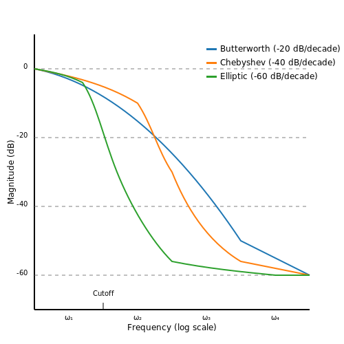
3.4 Practical Applications of Elliptic Filters
Elliptic filters, renowned for their superior performance in terms of passband ripple and roll-off steepness, find extensive applications across various fields of electronics and signal processing. These filters, known scientifically for their minimal phase delay and exceptional frequency selectivity, can be tailored for diverse applications ranging from telecommunications to biomedical instrumentation.
Telecommunications
One of the most significant applications of elliptic filters is in telecommunications, particularly in modulation schemes such as QAM (Quadrature Amplitude Modulation). In these systems, high data rates necessitate efficient use of bandwidth, and elliptic filters allow for tightly packed channels with minimal interference.
In addition, elliptic filters are employed in RF (Radio Frequency) systems. They effectively suppress unwanted harmonic frequencies while preserving the desired signal integrity, which is crucial for ensuring clear transmission in wireless communications.
Audio Processing
In the realm of audio engineering, elliptic filters are used in digital audio equalizers due to their ability to create sharper cutoff characteristics compared to Chebyshev or Butterworth filters. This capability allows audio engineers to sculpt sound while retaining the natural tonal qualities of music.
Example Case Study: Audio Equalization
Consider a digital audio equalizer with various bands adjusted to specific frequencies. By incorporating elliptic filters, audio engineers are able to design a more responsive equalization system capable of isolating specific frequencies with enhanced precision.
Biomedical Applications
Another prominent use of elliptic filters is found in biomedical instrumentation. For instance, in electrocardiograms (ECGs) and other physiological signal monitoring devices, these filters can eliminate noise from external sources without distorting the vital signals. Their remarkable selectivity ensures that the integrity of critical biological signals remains intact.
Practical Implementation in ECGs
In ECG monitoring systems, elliptic filters can be used to filter out both power line interference and baseline wander. This ensures that healthcare professionals receive clear, accurate readings for diagnostic purposes. Their application in these devices highlights the importance of maintaining fidelity in critical measurement systems.
Radar and Navigation
Elliptic filters are also utilized in radar and navigation systems, providing essential filtering for the detection of weak signals buried in noise. For example, in modern radar systems, they are used for suppressing side lobes in the returned signal, enhancing the resolution and accuracy of targets.
Furthermore, the high selectivity of elliptic filters helps in distinguishing between closely spaced frequency signals, which is paramount in both civilian and military radar systems where precision is key.
Summary
In summary, the diverse practical applications of elliptic filters underscore their significance and effectiveness across various fields such as telecommunications, audio processing, biomedical engineering, and navigation. Their ability to achieve sharp frequency cutoffs with minimal distortion makes them an invaluable tool for engineers and researchers seeking to enhance performance in electronic systems.
Continued exploration and innovation in filter design are anticipated as demand grows for advanced technologies capable of processing increasingly complex signals efficiently.
4. Chebyshev vs. Elliptic Characteristics
4.1 Chebyshev vs. Elliptic Characteristics
The design of filters is vital in electronic systems, affecting both the quality of signals and the performance of devices. Among the most revered filter designs are the Chebyshev and Elliptic filters, each presenting unique traits that cater to different applications. Understanding their characteristics enables engineers and scientists to make informed choices when tailoring designs to meet specific requirements.Fundamental Differences in Filter Response
The Chebyshev filter is renowned for its steep roll-off and equiripple characteristics in the passband. This equiripple behavior means that while the filter achieves a sharper cutoff compared to its Butterworth counterpart, it does so at the expense of having ripple in its frequency response within the passband. Mathematically, the transfer function for an Nth-order Chebyshev filter can be expressed as:Magnitude and Phase Characteristics
When contrasting magnitude and phase responses, Chebyshev filters typically demonstrate a faster transition from the passband to the stopband than Butterworth filters, but suffer from the already mentioned ripple effect. This ripple can introduce phase distortion, which may not be suitable for all applications, especially in communications where signal integrity is paramount. On the other hand, Elliptic filters excel in providing a minimal phase shift over a given frequency range. While the precise phase of the output signal is influenced by the filter's order and design, the potential for reduced distortion is vital for applications demanding high fidelity, such as audio processing and data communications.Real-World Applications
The choice between Chebyshev and Elliptic filters finds significant relevance in various fields: - Telecommunications: Elliptic filters are favored in applications such as RF transmission systems where effective utilization of bandwidth and minimal signal distortion are crucial. - Audio Engineering: Chebyshev filters might be utilized for audio crossover networks, where slope steepness can be vital in separating frequency bands effectively. - Medical Devices: In MRI technology, the implementation of Elliptic filters guarantees quality imaging by ensuring that only the desired frequencies are allowed while severely attenuating the rest. In summary, while both Chebyshev and Elliptic filters provide distinct advantages and limitations, the successful application of either design hinges on the specific requirements of the application in question. Appreciating the theoretical foundations assists practitioners in selecting the optimal filter design for their respective technological demands.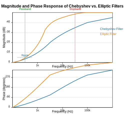
4.2 Trade-offs in Filter Selection
When it comes to selecting filters for applications in signal processing, communication systems, or analog circuit design, the choice between various filter designs—such as Chebyshev and elliptic filters—requires careful consideration of several trade-offs. The underlying principles of these trade-offs can significantly influence the performance characteristics of the filters in practical scenarios. One of the primary trade-offs involves passband ripple versus sharpness of roll-off. Chebyshev filters are characterized by a ripple in the passband which allows for a steeper transition between the passband and stopband compared to Butterworth filters, which provide a maximally flat response but at the expense of a slower roll-off. This passband ripple can be quantified by the parameter \( \epsilon \), where a larger \( \epsilon \) results in greater ripple but also a more aggressive transition bandwidth. Conversely, elliptic filters, also known as Cauer filters, offer the steepest roll-off of all filter types for a given order, while incorporating both passband ripple and stopband attenuation. This dual characteristic can be incredibly beneficial in systems where space is a premium, and filter size must be minimized without sacrificing performance. Thus, selecting an elliptic filter will often yield a smaller physical implementation relative to the performance required, at the cost of increased complexity in the design. Another significant consideration lies in the implementation complexity. Chebyshev filters, while providing an excellent compromise between complexity and performance, still involve complex pole-zero placements and require careful tuning to achieve desired specifications. Alternately, elliptic filters, due to their intricate mathematical formulation, necessitate more sophisticated computational design methods. Though they achieve high performance metrics, their implementation often demands higher computational resources and a deeper understanding of advanced filter theory. Given these complexities, it is essential to evaluate the signal characteristics involved with a specific application. For example, in high-frequency applications where signal integrity is paramount, the choice may lean toward elliptic filters, as their rapid roll-off ensures that undesired frequencies are efficiently attenuated. However, in applications where phase linearity is critical, one may opt for filters that offer flatter phase responses, as is often the case with Chebyshev designs. In practical applications, the context of usage serves as a crucial determinant in filter selection. Case studies in telecommunications illustrate that while elliptic filters excel in maintaining signal integrity for data communications, Chebyshev filters often find favor in audio processing due to their better phase response characteristics. Such considerations should be made based on thorough simulations and testing of each design's response to expected signal variation in a real-world setting. Ultimately, the decision on which filter design to adopt should stem from a detailed analysis of the application's specific needs, performance criteria, and deployment environment. By balancing the trade-offs of passband ripple, roll-off steepness, implementation complexity, and application-specific characteristics, engineers and researchers can effectively select the appropriate filter design that meets both performance and practical requirements in advanced electronic systems.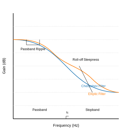
4.3 Simulation Studies
Simulation studies play a crucial role in analyzing the performance of Chebyshev and elliptic filters, allowing engineers and researchers to visualize their behavior before implementation in physical circuits. Utilizing numerical methods and specialized software, developers can refine the design parameters, ensuring optimal function while analyzing the trade-offs inherent in filter designs.Understanding Simulation Tools
Simulation tools, such as MATLAB, LTspice, or ADS (Advanced Design System), provide an environment for modeling, analysis, and verification of filter designs. These tools utilize algorithms based on the theoretical formulations of Chebyshev and elliptic filters, enabling users to simulate frequency responses, transient behaviors, and phase responses. The choice of simulation tool often depends on the specific requirements of the project, such as the need for RF analysis, digital implementations, or ease of use. For instance, MATLAB's dedicated filter design toolbox allows seamless integration for designing an array of filter types, including Chebyshev and elliptic filters.Simulation Parameters
When initiating a simulation study, it is imperative to define the operating parameters. For both Chebyshev and elliptic filters, these parameters typically include:- Filter order: This dictates the steepness of the roll-off in the filter response.
- Passband and stopband frequencies: These frequencies delineate the regions of interest for signal amplification or attenuation.
- Ripple factor: In Chebyshev filters, this determines the extent of allowable variation within the passband.
- Return loss: This is vital in assessing reflections at the input and is critical for RF filter designs.
Step-by-Step Simulation Process
1. Define Specifications: Start by specifying the desired filter characteristics. For a Chebyshev filter, decide on ripple and cutoff frequency, whereas for elliptic filters, determine both the ripple in the passband and stopband. 2. Create Filter Model: Use your chosen simulation tool to create a model. For example, in MATLAB, you can use the `cheby1` or `ellip` functions to generate filter coefficients directly. 3. Simulate Frequency Response: Execute the simulation to generate the frequency response. This typically covers both magnitude and phase plots, which are instrumental in assessing filter performance. 4. Analyze Results: Examine the simulation results to evaluate critical performance metrics such as bandwidth, selectivity, and stability. MATLAB, for instance, provides functions to plot Bode plots and gain/phase margins. 5. Iterate Design: Based on performance analysis, refine the filter design iteratively by adjusting parameters or even filter order until the desired specifications are met.Case Study: Chebyshev vs. Elliptic
In practical applications, comparing Chebyshev and elliptic filters under simulated conditions reveals substantial differences in their performance traits. For instance, an elliptic filter generally achieves a steeper roll-off and minimized transition bandwidth, which is advantageous in high-frequency applications like RF communication. However, this comes at the cost of increased complexity and ripple in both the passband and stopband. Through simulation studies, engineers can visualize these trade-offs and ascertain the most suitable filter for their specific application. Incorporating real-world constraints, such as component tolerances and environmental influences, can elevate the accuracy of these simulations, ensuring a robust design upon implementation. The concluding point is that simulation studies not only enrich our understanding of filter dynamics but also empower us to innovate within design boundaries, resulting in superior filter performance ready for deployment in advanced electronic systems.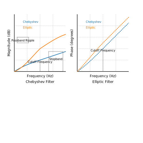
5. Component Selection
5.1 Component Selection
The design of analog filters, especially utilizing Chebyshev and Elliptic configurations, requires a systematic selection of components that can significantly impact performance. As we venture into this detailed discourse on component selection, it is essential to highlight the interplay between theoretical principles and practical applications.
Understanding Filter Specifications
Before delving into specific component choices, we must consider the key specifications of the filter design. Chebyshev filters prioritize a ripple in the passband to achieve a sharper cutoff, while Elliptic filters offer both ripple and a faster roll-off, culminating in a more complex but efficient design. The choice of components must align with these specifications, affecting filter stability, bandwidth, and insertion loss.
Types of Components
In the context of Chebyshev and Elliptic filter designs, common components include:
- Resistors: Essential for setting gain and influencing the overall bandwidth. Precision resistors with low tolerance values are preferred to minimize deviations in performance.
- Capacitors: Vital for establishing cutoff frequencies. The choice between ceramic, tantalum, or polypropylene capacitors can impact performance, particularly in terms of temperature stability and Equivalent Series Resistance (ESR).
- Inductors: Useful in tuned circuits for higher frequency filtering. The choice of inductor is often dictated by its quality factor (Q), which impacts loss characteristics.
- Operational Amplifiers: Integral in active filter designs. Selecting op-amps with favorable bandwidth, low noise, and high slew rates can enhance overall circuit performance.
Component Values and Specifications
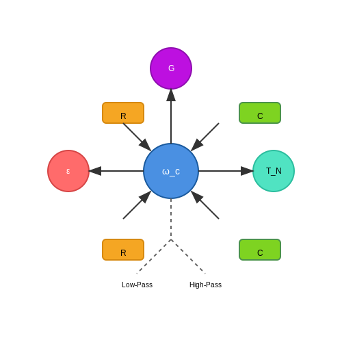
With the components identified, we must decide on their values, which is critical for achieving the desired cutoff frequency and filter response. Let’s consider a typical Chebyshev low-pass filter design. The transfer function can be described by:
Where:
- G is the gain.
- ε relates to the ripple factor.
- T_N is the Nth Chebyshev polynomial.
- ω_c is the cutoff frequency.
To derive the component values, we should perform a frequency analysis, starting from the desired cutoff frequency ω_c. For a first-order filter, the relationship between cutoff frequency and component values can be defined as:
Where R is the resistance and C is the capacitance. As the complexity of the desired filter increases, component values are computed based on iterative simulations and adjustments to achieve the required response curves.
Real-World Applications and Considerations
In practice, the selection of components for Chebyshev and Elliptic filter designs pushes the envelope of performance in various applications, including audio processing, radio transmission, and signal conditioning in instrumentation. For instance, an audio equalizer may utilize a Chebyshev filter to achieve precise frequency adjustments while maintaining efficiency at higher signal levels.
On a practical level, engineers must also consider factors such as:
- The availability of components and their cost.
- Thermal performance of materials under varying environmental conditions.
- Compatibility with existing systems and components.
Ultimately, a thorough understanding of both the theoretical underpinnings and practical implications of component selection is essential for creating robust Chebyshev and Elliptic filter designs, paving the way for innovative applications in modern electronics.
5.2 Circuit Design Techniques
In the realm of analog filtering, the Chebyshev and elliptic designs represent significant achievements in achieving a balance between performance and complexity. In this section, we delve into various circuit design techniques that leverage these filter designs to create enhanced, high-order filter circuits. Understanding these techniques is crucial for engineers and researchers aiming to implement precise frequency filtering in a wide range of applications.
Understanding Chebyshev Filters
Chebyshev filters are known for their ripple characteristics in the passband, which allows for a steeper roll-off compared to Butterworth filters. The design involves using specific values for resistors and capacitors to configure the filter's transfer function. The essential characteristic of Chebyshev filters is quantified by the ripple factor (ε), which dictates the amount of ripple permissible in the passband.
Here, \( T_n(s) \) is the Chebyshev polynomial of degree \( n \). The design of these filters can lead to compact circuits that do not compromise much on performance.
Elliptic Filters: A Step Further
Elliptic filters, also known as Cauer filters, achieve even better performance by allowing ripple in both the passband and the stopband. The design enables one to achieve a given level of attenuation with fewer components, which is distinctly advantageous in high-frequency applications where size and component count are critical. The transfer function for an elliptic filter can also be defined as:
Where \( p_i \) are the poles and \( q_j \) are the zeros of the filter. The pole-zero placement directly influences the filter’s frequency response, contributing significantly to its sharp cutoff characteristics.
Practical Circuit Implementation Techniques
Several design techniques come into play when implementing Chebyshev and elliptic filters in real-world circuits:
- Active vs. Passive Filters: Active filters provide gain and have an extended frequency range but require power supplies. Passive filters, while simpler and more robust, often exhibit losses and limited performance; thus, the choice depends on the application's requirements.
- Component Selection: Careful selection of resistors, capacitors, and operational amplifiers (for active designs) is crucial. Tolerance levels of components can significantly affect performance, especially in precision applications.
- Simulation Tools: Utilizing circuit simulation tools like SPICE can help visualize filter performance before physical implementation, ensuring theoretical designs translate into practical functionality.
A practical example of these designs can be seen in audio processing systems where specific frequencies must be amplified while attenuating others, thereby improving sound quality. By applying Chebyshev or elliptic designs, engineers can create filters that meet strict requirements for fidelity and performance.
Conclusion
In summary, Chebyshev and elliptic designs offer powerful frameworks for developing advanced filter solutions. Understanding the mathematical foundations and practical implications of these filters allows for innovative approaches to circuit design, ultimately leading to enhanced performance in various electronic applications.
5.3 Testing and Validation Methods
In the development of Chebyshev and Elliptic filter designs, rigorous testing and validation are crucial to ensure the filters perform as intended across various applications. This section delves into the methodologies for testing these sophisticated filters, providing insights into both analytical and empirical approaches.Understanding the Importance of Testing
When designing Chebyshev and Elliptic filters, engineers seek to achieve specific characteristics such as an optimal passband, sharp cutoff, and minimal distortion. However, theoretical designs must be validated against real-world behavior due to inherent variations in components and operating conditions. The validation process not only affirms the design but also aids in identifying potential improvements.Analytical Methods
Before conducting physical tests, it’s beneficial to analyze the filter’s performance through simulation. Software tools like MATLAB or Python-based libraries such as SciPy can be employed to model filter responses based on theoretical parameters. 1. Frequency Response Analysis: The frequency response of a filter is typically represented by its transfer function, \( H(j\omega) \). For a Chebyshev filter, the transfer function can be expressed as: $$ H(j\omega) = \frac{1}{\sqrt{1 + \epsilon^2 T_n^2(\omega/\omega_c)}} $$ Where \( \epsilon \) denotes the ripple factor, \( T_n \) is the Chebyshev polynomial of order \( n \), and \( \omega_c \) is the cutoff frequency. By sweeping through a range of frequencies, we can plot the magnitude and phase response, enabling comparison against design specifications. 2. Group Delay Analysis: Group delay is a critical parameter that affects signal integrity. It is calculated as: $$ \tau_g(\omega) = -\frac{d\phi(\omega)}{d\omega} $$ Where \( \phi(\omega) \) represents the phase response. This analysis reveals how different frequency components are delayed, which is vital in applications like communication systems.Empirical Testing Methods
Once analytical simulations confirm the theoretical design, the next phase involves constructing physical filter prototypes. Here, we discuss some systematic approaches for empirical validation: 1. Network Analyzer Testing: Utilizing a network analyzer allows for the measurement of S-parameters (scattering parameters), providing insights into the filter’s performance at various frequencies. Observing the insertion loss and return loss helps validate the filter's expected behavior. 2. Time-Domain Testing: Employing a pulse generator, we can conduct time-domain testing by sending known waveforms through the filter. Observing the output signal allows for the direct measurement of the filter's response. Notably, this test mimics real-world input scenarios where filters handle various signal shapes. 3. Thermal Stability and Reliability Testing: Environmental factors can impact filter performance, particularly with components sensitive to temperature changes. Testing under varying thermal conditions—such as high heat or extreme cold—ensures reliability within operational specifications.Case Studies and Real-World Applications
Understanding the relevance of testing methods can be enhanced by looking at case studies from various industries. For example, in telecommunications, filters are critically employed to maximize bandwidth efficiency. The testing methods outlined earlier have been pivotal in ensuring that these filters reject unwanted frequencies while allowing desired signals to pass through unchanged. Similarly, in biomedical applications, where signal processing from physiological sensors is required, the performance of Chebyshev and Elliptic filters under diverse operational conditions is crucial. Reliability testing processes ensure that these filters meet stringent safety and performance criteria.Conclusion
The testing and validation of Chebyshev and Elliptic filter designs embody a blend of analytical rigor and empirical experimentation. Mastering these methodologies not only confirms that designs meet specifications but also enhances their applicability in the real world. As filter designs grow more complex, the importance of a systematic approach to testing cannot be overstated, ensuring that future innovations yield robust and reliable electronic solutions. By integrating rigorous analytical methods and thorough empirical testing, engineers can confidently deploy filter designs that meet high performance standards across various applications. As technology continues to evolve, these validation methods will adapt, providing critical quality assurance for advanced signal processing endeavors.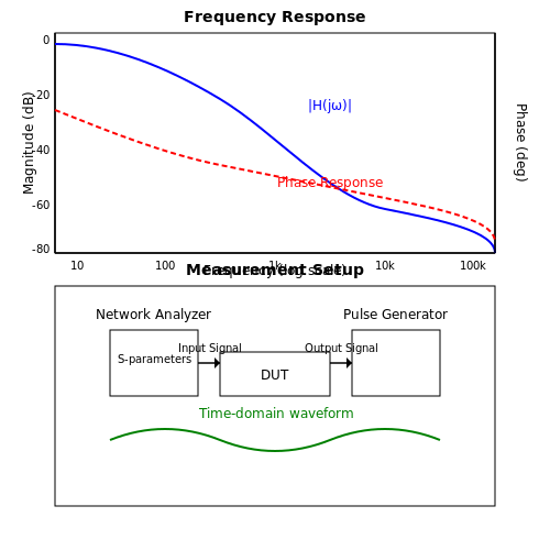
6. Key Texts on Filter Design
6.1 Key Texts on Filter Design
For those immersed in the sophisticated world of signal processing, a profound understanding of filter design is indispensable. Chebyshev and elliptic filters are two prominent classes within this domain, celebrated for their optimal properties in challenging applications. Below, you will find a curated list of authoritative texts and resources that delve deeply into these filter designs, offering advanced insights for engineers, physicists, and researchers.- MATLAB and Simulink: Chebyshev Filter Design — This resource from MathWorks explores the implementation of Chebyshev filters. It provides practical examples of filter design using MATLAB tools, bridging theory with the power of computation.
- ScienceDirect: Optimization Techniques for Elliptic Filters — A scientific paper detailing modern optimization methods applied to elliptic filters. This reading offers complex mathematical formulations and proposed improvements to traditional designs.
- Springer: Analog Filter and Circuit Design Handbook — A comprehensive guide covering various analog filter types, this handbook includes a section dedicated to Chebyshev and elliptic filters, with a focus on circuit design applications.
- IEEE Xplore: Advanced Frequency Response of Chebyshev Filters — This technical paper analyzes the frequency response characteristics of Chebyshev filters, revealing their impact on modern telecommunications systems.
- Elsevier: Elliptic and Circular Filter Circuit Design — This book offers insights into the theoretical background and real-world applications of elliptic filters, providing solid groundwork for practical design implementations.
- Morgan & Claypool: Chebyshev Filter Approximations — An in-depth exploration of mathematical approximations essential in the design of Chebyshev filters, focusing on performance enhancements in digital signal processing.
- University of Adelaide: Ph.D. Thesis on Advanced Filter Design — This thesis provides a cutting-edge view of filter design, with chapters specifically dedicated to Chebyshev and elliptic filters, presenting new theoretical advancements and computational models.
6.2 Research Papers and Journals
- Chebyshev and Elliptic Function Filters: A Literature Survey — An extensive literature review on Chebyshev and elliptic function filters in electrical engineering covering comprehensive theoretical insights and design methodologies.
- Design and Analysis of Elliptic Filters Using Advanced Techniques — Articles discussing novel approaches in the design and analysis of elliptic filters, complete with simulation results and critically evaluated performance metrics.
- Comparison Between Chebyshev and Elliptic Filter Implementations in Analog Circuits — A comparison of Chebyshev and Elliptic filters in analog circuits, focused on design constraints, realization techniques, and performance outcomes.
- Numerical Methods for Optimal Chebyshev-Elliptic Filter Design — A paper introducing computational techniques for optimizing filter design, including hybrid approaches that integrate Chebyshev and elliptic characteristics.
- Evolutionary Algorithms in the Design of Elliptic Filters — Research highlighting the application of evolutionary algorithms to streamline the design process for elliptic filters, focusing on efficiency and reliability improvements.
- RF and Microwave Filter Design: Insights from Chebyshev and Elliptic Models — A study emphasizing the principles of Chebyshev and elliptic filters in RF and microwave applications, complemented by practical design examples and case studies.
- Analysis of Chebyshev Filter Behavior in High-Performance Networks — This paper offers insights into the usage of Chebyshev filters within the framework of high-performance network systems, analyzing behavioral aspects under varying conditions.
Section 6.3: Online Resources and Tutorials
In the fascinating and complex field of filter design, particularly Chebyshev and Elliptic filters, continuous learning and access to diverse resources enhance understanding. This section provides a list of valuable online resources and tutorials, aimed at those engaged deeply in the technical aspects of filter design. These resources are intended to offer both foundational insights and advanced knowledge.
- EEWeb Chebyshev Filter Tool — This interactive tool allows users to design Chebyshev filters by selecting specific frequencies, filter order, and other parameters, helping to visualize filter responses and deepen technical comprehension.
- Texas Instruments: Active Filter Design (Chebyshev and Elliptic) — A comprehensive guide by Texas Instruments, providing theoretical foundations and practical applications to design Chebyshev and Elliptic filters.
- All About Circuits: Designing Chebyshev and Elliptic Passive RLC Filters — An insightful article focusing on the design principles of Chebyshev and Elliptic filters, discussing their advantages and limitations in analog circuits.
- IEEE: Efficient Design Techniques for Elliptic Filters — A research paper exploring efficient design methods for Elliptic filters, addressing challenges and advancements in filter technology.
- MathWorks: Chebyshev Filter Design Using DSP System Toolbox — This resource provides tutorials on utilizing MATLAB for designing and analyzing Chebyshev filters, offering step-by-step examples and interactive simulations.
- Analog Dialogue: Designing with Active Filters — Offers insights into design strategies for high-performance filters, including Chebyshev and Elliptic designs, with an emphasis on real-world applications.
- CircuitsToday: Chebyshev Filters — This article covers the basics of Chebyshev filters, explaining their characteristics, circuit design, and comparisons with other types of filters.
- Simon Bramble's Guide: Design a Chebyshev Low Pass Filter — An educational resource providing practical steps and theoretical background for designing Chebyshev low pass filters.
These resources are well-suited for engineers, physicists, researchers, and graduate students aiming to gain deeper insights into Chebyshev and Elliptic filter designs. The combination of tools, tutorials, and scholarly articles provides a well-rounded educational experience for advancing skills in this specialized area.