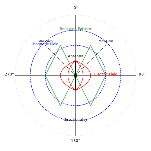
Coaxial Cable Characteristics
1. Physical Structure and Components
1.1 Physical Structure and Components
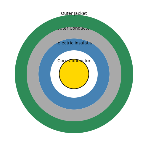
Coaxial cables play a crucial role in modern telecommunications and data transmission systems, primarily due to their unique physical structure. Understanding these components provides insights into their operational characteristics, including impedance, attenuation, and frequency response. Let's delve into the individual elements that constitute a coaxial cable and their respective functionalities.
Core Conductor
At the heart of a coaxial cable lies the core conductor, often made from solid copper or copper-clad steel. This central wire is responsible for carrying the electrical signals. The choice of material directly impacts the conductivity and overall performance of the cable. For instance, pure copper offers superior conductivity compared to steel, making it preferable for high-frequency applications.
Dielectric Insulation
Surrounding the core conductor is a layer of dielectric insulation, typically made from materials like polyethylene, foam, or Teflon. This insulator serves several roles:
- Electrical Isolation: It separates the inner conductor from the outer shield, preventing unwanted current paths.
- Impedance Control: The dielectric material helps define the cable's characteristic impedance, which is crucial for minimizing signal reflection and ensuring efficient transmission.
- Signal Integrity: A higher-quality dielectric material can reduce signal loss and maintain the integrity of high-frequency signals.
Outer Conductor
The outer conductor, typically a braided or solid metal sheath, acts as the cable’s shield. Its primary functions encompass:
- Electromagnetic Shielding: The outer conductor protects the signal from external electromagnetic interference (EMI) and environmental noise, preserving signal quality.
- Return Path: It provides a return path for the signal, ensuring uninterrupted communication and effective grounding.
Additionally, the design and material of the shield can affect the cable's overall performance, influencing parameters like attenuation and maximum frequency capabilities.
Outer Jacket
Finally, the coaxial cable is encased in an outer jacket made of durable materials such as PVC or polyethylene. This protective layer safeguards the internal components from physical damage, moisture, and chemicals. Depending on the intended application, the jacket may also be designed to withstand outdoor exposure or high temperatures.
Applications and Relevance
The physical makeup of a coaxial cable directly affects its application in various fields. For example, RG-6 cables with thicker dielectric insulation and enhanced shielding are ideal for satellite and cable television installations where minimal signal loss is paramount. Conversely, RG-59 cables, which are thinner, are commonly used for analog video signals where the distances are short, and minimal levels of interference are required.
In summary, the unique physical structure of coaxial cables, composed of the core conductor, dielectric insulation, outer conductor, and protective jacket, determines their suitability for various applications across telecommunications, broadcasting, and networking domains. Understanding these components allows engineers and technicians to select the appropriate cable type for specific tasks, optimizing performance and reliability.
1.2 Electric Properties: Impedance and Capacitance
Coaxial cables are integral components in modern communication systems, with their performance heavily influenced by electrical parameters such as impedance and capacitance. Understanding these characteristics is crucial for engineers and designers seeking to optimize signal integrity and minimize loss in various applications.
Impedance: Definition and Relevance
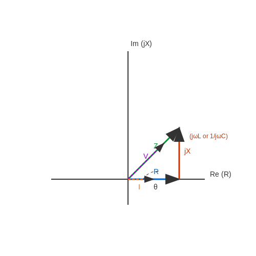
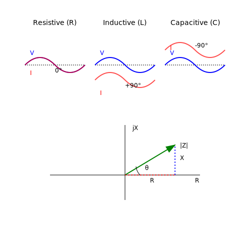
Impedance, denoted as Z, represents the total resistance that a circuit presents to alternating current (AC). For coaxial cables, it is primarily determined by the geometry of the cable and the materials used. The characteristic impedance can be defined by the equation:
where L is the inductance per unit length and C is the capacitance per unit length. This relationship signifies that both inductance and capacitance play a crucial role in determining how effectively a coaxial cable can transmit AC signals.
Analyzing Capacitance
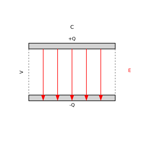
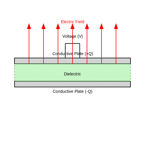
Capacitance in coaxial cables arises due to the configuration of the inner and outer conductors, where the electric field exists between them. The capacitance per unit length can be expressed as:
In this equation, ε is the permittivity of the dielectric material, and a and b are the radii of the inner and outer conductors, respectively. The logarithmic term highlights the influence of the conductor dimensions on the overall capacitive behavior of the cable.
Practical Applications and Importance
The understanding of impedance and capacitance is essential in designing transmission lines to ensure maximal power transfer and minimize reflections at connections. In applications such as RF transmission, video signal distribution, and high-speed data communication, an impedance mismatch can lead to significant performance degradation. Thus, engineers must carefully select cables with appropriate characteristics for their specific applications.
For example, standard coaxial cables used in video applications typically have a characteristic impedance of 75 ohms, while cables used for radio frequency applications often have 50 ohms characteristic impedance. The choice between these types directly impacts signal integrity and transmission efficiency.
Conclusion
The electrical properties of coaxial cables, particularly impedance and capacitance, are pivotal in dictating their behavior in practical applications. Understanding these properties enables engineers to make informed decisions during the design and implementation of communication systems, ensuring optimal performance and reliability.

1.3 Mechanical Properties: Flexibility and Strength
Understanding the mechanical properties of coaxial cables, particularly their flexibility and strength, is essential for engineers and researchers working with various communication and electronic systems. These properties not only influence the installation and handling of the cables but also affect their overall performance in practical applications.
Coaxial cables are typically designed with an inner conductor, an insulating layer, an outer conductor, and an outer jacket. The combination of materials used in these components contributes significantly to the mechanical properties of the cable. Flexibility refers to the ability of the cable to bend without breaking, whereas strength encompasses the cable’s ability to withstand mechanical stress without deforming or losing its integrity.
Flexibility
The flexibility of a coaxial cable is largely determined by its construction and the materials used. For example, using softer materials for the dielectric insulator and the external jacket can enhance the cable's bendability. Flexibility is crucial in applications where cables must be routed in tight spaces or around curves. In environments such as mobile vehicles and industrial locations, a more flexible cable can endure repetitive bends and twists, ultimately leading to longer service life and reduced failure rates.
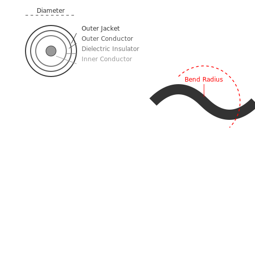
The bend radius is a critical factor in measuring the flexibility of coaxial cables. It is defined as the minimum radius that the cable can bend without incurring damage. As a general rule, the bend radius is typically 10 times the external diameter of the cable. For instance, if a coaxial cable has a diameter of 5 mm, the minimum bend radius would be 50 mm. This parameter is highly significant in installations where cables must navigate tight turns.
Strength
In addition to flexibility, the strength of a coaxial cable is equally important; it defines how well the cable can withstand mechanical stresses such as tensile and compressive forces. Tensile strength is particularly vital in outdoor environments where cables are frequently subjected to pulling forces, for instance, during installation or due to the weight of the cable itself. The selection of materials like high-tensile strength polymers and metals can substantially improve the overall resilience of the cable.
Furthermore, crush resistance is another aspect of strength that must be considered, especially for outdoor and direct burial cables that may experience heavy loads from objects above them. Appropriate design choices, such as using reinforced outer jackets or braided shields, bolster the cable's ability to resist these forces. Testing standards, such as those defined by the International Electrotechnical Commission (IEC), provide guidelines for assessing these mechanical characteristics.
In real-world applications, the interplay between flexibility and strength dictates the choice of coaxial cables for specific tasks. For instance, in broadcasting or telecommunications, cables requiring extensive routing and movement benefit from enhanced flexibility, while military and aerospace applications prioritize strength to ensure durability under extreme conditions.
In summary, the balance of flexibility and strength in coaxial cable design plays a pivotal role in their functionality and performance across various industries. The selection of materials and the engineering of specific geometries can lead to optimally designed cables suited to the precise needs of the application.
2. Signal Loss: Types and Causes
2.1 Signal Loss: Types and Causes
Signal loss in coaxial cables is a critical factor that impacts the performance and efficiency of data transmission. Understanding the various types of signal loss and their causes is essential for engineers, physicists, and researchers involved in designing and maintaining communication systems. This section will delve into the intricacies of signal loss, categorizing it into types and examining their underlying causes.
Types of Signal Loss
Signal loss can primarily be classified into two types: attenuation and reflection. Both of these phenomena contribute to the degradation of signal quality in coaxial cables.
Attenuation
Attenuation refers to the gradual loss of signal strength as it travels through the coaxial cable. This loss can be quantified using the attenuation constant, denoted by the symbol α, expressed in decibels per unit length (typically dB/km). The primary factors contributing to attenuation include:
- Conductor Loss: Resistance in the cable conductors results in energy dissipation in the form of heat.
- Dielectric Loss: Energy is lost in the dielectric material surrounding the conductors due to its finite conductivity.
- Radiation Loss: Some energy may escape as electromagnetic radiation, particularly for poorly shielded cables.
Reflection
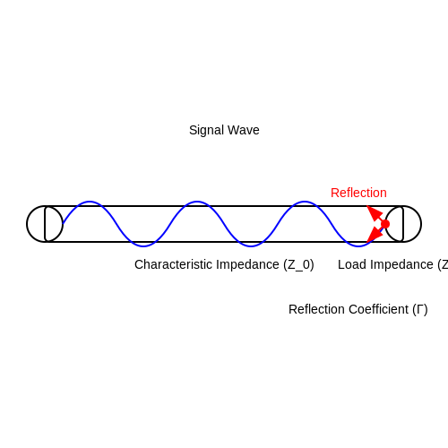
Reflection occurs at points where there is a discontinuity in the characteristic impedance of the coaxial cable, often caused by connectors, junctions, or changes in cable diameter. This mismatch results in part of the signal being reflected back towards the source, effectively decreasing the amount of usable signal. The reflection coefficient (Γ) quantifies this effect and is defined as:
where Z_L is the load impedance and Z_0 is the characteristic impedance of the cable. A high reflection coefficient indicates significant signal loss due to reflection, which is critical in applications requiring high fidelity.
Causes of Signal Loss
Several factors contribute to the overall signal loss in coaxial cables, with environmental and physical conditions playing a significant role. Key causes include:
- Cable Length: Longer cables incur more attenuation, which aligns with the logarithmic nature of the attenuation constant.
- Frequency: Higher frequencies experience greater attenuation and reflection, largely due to skin effect and dielectric losses.
- Temperature: The resistance of conductive materials varies with temperature, thereby affecting attenuation.
- Mechanical Stress: Bending or twisting the cable can alter its impedance characteristics and lead to increased reflection.
Understanding these types and causes of signal loss is vital for optimizing coaxial cable installations and ensuring that transmission systems operate at their intended efficiencies. By addressing the aforementioned factors, engineers can implement measures to mitigate signal loss in critical applications such as telecommunications, broadcasting, and networking.
2.2 Bandwidth and Frequency Response
The characteristics of coaxial cables are instrumental in various applications, particularly in telecommunications and data transmission. One of the critical parameters that define the performance of coaxial cables is their bandwidth and frequency response. Understanding these concepts is essential for engineers and researchers who seek to optimize signal transmission in practical applications.
Understanding Bandwidth in Coaxial Cables
The bandwidth of a coaxial cable is defined as the range of frequencies it can transmit with minimal signal loss. In essence, it determines the amount of data or information a cable can carry over a specific time period. The bandwidth is influenced not only by the physical dimensions of the cable (including the inner and outer conductor diameters) but also by the insulating materials used and the overall quality of construction.
Mathematically, the bandwidth (B) can be approximated for coaxial cables using the formula:
Where:
- R is the resistance per unit length of the cable.
- C is the capacitance per unit length of the cable.
Here, higher bandwidth is typically associated with lower resistance and capacitance, enabling efficient signal transmission at a plethora of frequencies.
Frequency Response and Its Importance
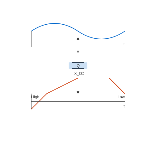
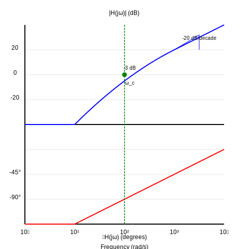
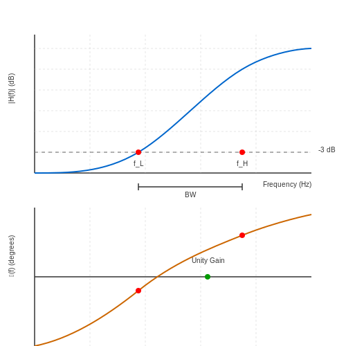
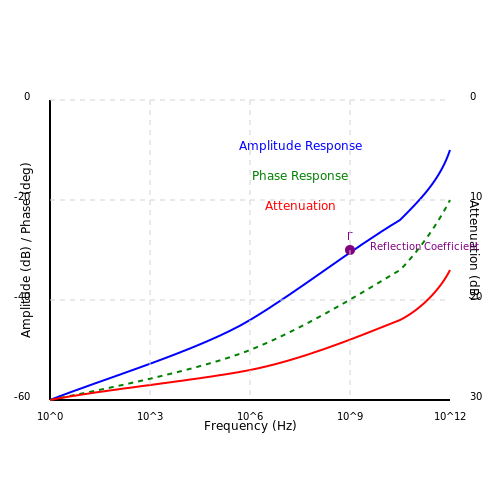
Frequency response describes how a coaxial cable behaves at different frequencies, encapsulating its ability to transmit signals accurately over its bandwidth. This behavior can be visualized in the form of a frequency response curve, showcasing how the amplitude and phase of the output signal vary relative to the input signal across a range of frequencies.
Key to evaluating a cable's frequency response is the understanding of two significant phenomena: attenuation and reflection.
Attenuation
Attenuation refers to the reduction in signal strength as it travels through the coaxial cable. The attenuation factor can be mathematically represented by:
Where:
- Pin is the input power and Pout is the output power.
Usually, attenuation increases with frequency, implying that higher frequency signals suffer more loss and call for careful consideration when selecting cable types for specific applications.
Reflection
Reflection occurs at impedance mismatches along the cable. This phenomenon can lead to signal degradation and is quantified by the reflection coefficient (Γ), given by:
Where:
- ZL is the load impedance and Z0 is the characteristic impedance of the coaxial cable.
A strong understanding of reflection and attenuation is crucial for designing systems that aim to minimize signal integrity issues, especially in high-frequency applications such as RF communications and high-speed data networks.
Practical Applications and Implications
Knowing the bandwidth and frequency response characteristics of coaxial cables directly influences the design choices made in various fields. For instance:
- Television and Radio Broadcasting: High bandwidth allows for the transmission of multiple channels, enhancing the user experience.
- Data Networks: Optimized frequency response ensures minimal data loss and maximal throughput in Ethernet and other data transmission standards.
- RF Applications: In radar and communication systems, precise control of bandwidth and understanding of frequency response contributes significantly to system performance.
In summary, a thorough comprehension of bandwidth and frequency response not only guides the selection of appropriate cables for specific tasks but also informs the engineering practices necessary for maintaining signal integrity across a range of applications.
2.3 Reflection and Standing Wave Ratio (SWR)
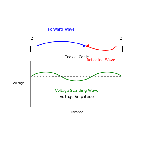
The characteristics of coaxial cables are pivotal in the design and implementation of high-frequency circuits, and understanding the concepts of reflection and standing wave ratio (SWR) further refines this knowledge. Reflection occurs whenever there is a change in impedance along the transmission line, which leads to a portion of the signal being reflected back towards the source. This phenomenon is key to comprehending how coaxial cables behave under operational conditions.
In any transmission line, including coaxial cables, reflection can be quantified with the reflection coefficient \( \Gamma \). This coefficient is defined as:
Where:
- ZL is the load impedance.
- Z0 is the characteristic impedance of the cable.
When \( \Gamma \) is zero, there is no reflection — meaning the load impedance perfectly matches the characteristic impedance of the cable. Conversely, a complete reflection occurs when \( \Gamma \) equals one, resulting in no power transmitted to the load. This is a critical consideration for engineers when designing systems that use coaxial cables, as impedance mismatches can lead to reduced efficiency and signal degradation.
Understanding the Standing Wave Ratio
The standing wave ratio (SWR) is a quantitative measure that describes the degree of impedance mismatch in a transmission line. The SWR is intrinsically linked to the reflection coefficient and is defined by the equation:
A key point to note is that an SWR of 1:1 represents ideal conditions with no mismatch, while ratios greater than this signify increasing levels of mismatch. For practical applications, an SWR of 2:1 is often considered acceptable in RF applications to minimize potential losses.
To put these concepts into context, consider a case study involving RF antennas. When designing an antenna feeding system, it is vital to minimize reflections caused by impedance mismatches to ensure maximum power transfer. Here, using a network analyzer, engineers can measure the SWR and determine adjustments required for optimal performance.
Real-world Applications and Importance
Mastering reflection and SWR is essential in various domains, including telecommunications, RF engineering, and broadcasting. Engineers utilize this knowledge to troubleshoot systems effectively, optimize circuit designs, and ensure the integrity of high-frequency signals. For instance, in wireless communication systems, maintaining manageable levels of SWR helps prevent signal loss and distortion, thus ensuring clearer transmission quality.
In conclusion, a thorough understanding of reflection and standing wave ratio in coaxial cables not only enhances system performance but also fosters improved designs that leverage optimal impedance matching. Beyond theory, these concepts translate into practical capabilities when addressing real-world challenges in advanced electronic systems.
3. Effects of Temperature and Humidity
3.1 Effects of Temperature and Humidity
Understanding the effects of temperature and humidity on coaxial cable performance is crucial for engineers and researchers working in telecommunications and data transmission. Coaxial cables are extensively used for RF communication, internet connectivity, and cable television. However, environmental factors, particularly temperature and humidity, can have significant impacts on their electrical properties, including impedance, attenuation, and signal integrity.
Temperature Effects
Temperature variations influence the dielectric constant of the insulating materials within coaxial cables, which in turn affects the signal propagation speed and overall attenuation. The relationship between temperature and the dielectric constant can often be described by a linear approximation:
Where:
- \(\epsilon(T)\) is the dielectric constant at temperature T.
- \(\epsilon_0\) is the dielectric constant at a reference temperature T0.
- \(\alpha\) is the temperature coefficient of the dielectric constant.
As the temperature increases, the dielectric constant usually decreases for most materials, leading to increased signal speed but also exacerbated dielectric losses, thus increasing signal attenuation. For example, polyethylene, a common dielectric in coaxial cables, shows a temperature coefficient of approximately -0.0009 per degree Celsius.
Practical Relevance
In practical applications, engineers must compensate for these variations in temperature when designing systems that rely on precise impedance and attenuation characteristics. For instance, in long-distance signal transmission, calculating the expected signal degradation over varying temperatures can improve reliability and performance in real-world conditions.
Humidity Effects
Humidity, often overlooked, plays a significant role in the performance of coaxial cables. Water vapor can penetrate the cable structure, particularly if cable integrity is compromised. The introduction of moisture can modify the effective permittivity of the dielectric material, resulting in further signal attenuation and potential phase shifts in the signal. The interaction between water and cable materials can be modeled as follows:
Where:
- AH denotes attenuation as a function of humidity H.
- A0 represents baseline attenuation in dry conditions.
- \(\beta\) is a constant that quantifies the cable's sensitivity to humidity levels.
Higher humidity levels often lead to increased losses, especially in frequency-dependent applications. Hence, coaxial cables operating in high-humidity environments may require special design considerations, such as moisture-resistant materials or protective outer layers.
Real-World Applications
In regions with extreme humidity, such as coastal areas, coaxial cables are subjected to more frequent performance degradation. This necessitates the deployment of more robust cable materials and protective measures in both installation and maintenance practices. Engineers should evaluate these environmental factors in concert with anticipated operational conditions to ensure sustainable performance.
Summary
Temperature and humidity significantly impact the electrical characteristics of coaxial cables. By understanding and quantifying these effects, engineers can enhance the performance and reliability of communication systems across diverse environments. This knowledge is indispensable in designing resilient networks capable of maintaining signal integrity under variable conditions.
3.2 Impact of External Interference
The performance of coaxial cables can be significantly affected by external interference, which poses critical challenges in various applications, particularly in communication and signal processing systems. Understanding the sources and consequences of such interference is essential for engineers and physicists aiming to enhance cable performance and reliability.
Types of External Interference
Coaxial cables are vulnerable to several forms of external interference. The primary sources include:
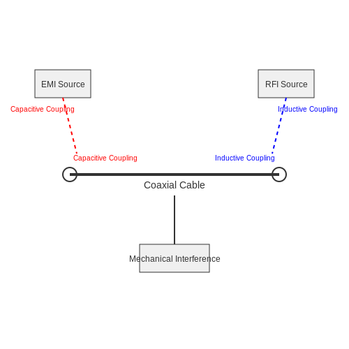
- Electromagnetic Interference (EMI): This can originate from nearby electrical devices, radio frequency transmitters, or fluctuating magnetic fields. EMI can induce unwanted signals in the cable, degrading the quality of the transmitted signal.
- Radio Frequency Interference (RFI): Similar to EMI, RFI specifically relates to interference from radio-frequency sources. It can affect the performance of coaxial cables, especially in high-frequency applications.
- Mechanical Interference: Physical pressures or movements can also impact coaxial cables, causing deformation and resulting in loss of signal integrity.
Mechanisms of Interference
The interference experienced by coaxial cables can be analyzed through multiple mechanisms. Understanding these mechanisms not only illuminates the phenomenon of signal degradation but also offers pathways for mitigation strategies.
1. Inductive Coupling
Inductive coupling is a common mechanism whereby a changing magnetic field induces a current in the conductor of the coaxial cable. The induced current competes with the intended signal, leading to distortions.
2. Capacitive Coupling
Capacitive coupling occurs when voltage differences create electric fields that induce unwanted currents. This interference is particularly pronounced in environments with high voltage fluctuations.
3. Reflective Interference
Signals can reflect at discontinuities along the cable, such as connectors or terminations. However, external signals can also initiate reflections, leading to constructive or destructive interference patterns, adversely affecting signal strength.
Quantifying the Impact of Interference
The impact of external interference can be quantified using the concept of Signal-to-Noise Ratio (SNR), which can be expressed as follows:
Where:
- Psignal: Power of the desired signal.
- Pnoise: Power of the interference (noise).
A higher SNR indicates a cleaner signal, whereas a lower SNR suggests that noise dominates, potentially leading to errors in signal interpretation. Ensuring a robust SNR is critical in the design and deployment of coaxial cable systems.
Mitigation Strategies
To minimize the effect of external interference, several practices can be employed:
- Shielding: Utilizing high-quality materials for the cable shield can block EMI and RFI effectively.
- Cable Routing: Careful planning of cable paths—avoiding high interference areas—can reduce exposure to other electromagnetic sources.
- Twisted Pairs: Implementing twisted pairs within coaxial arrangements could help in canceling out induced voltages.
As coaxial cables continue to be critical in high-frequency applications encountered in telecommunications and broadcasting, understanding and mitigating external interference parameters will enhance their efficacy, ensuring fidelity in signal transmission.
3.3 Installation Practices and Their Effects
Coaxial cables are a prevalent choice in telecommunications and networking due to their ability to transmit signals over extended distances with minimal loss. However, the performance and reliability of coaxial cables can be significantly affected by installation practices. Understanding the nuances of these practices is crucial for engineers and technicians aiming to optimize coaxial networks.
Impact of Bending and Twisting
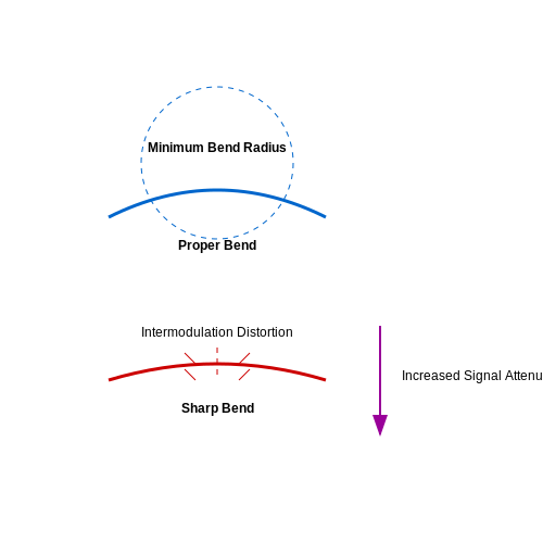
One of the fundamental installation practices that can influence a coaxial cable's performance is how it is bent or twisted during installation. Bending a coaxial cable beyond its minimum bend radius can lead to various issues, including:
- Increased signal attenuation: Sharp bends can cause a reduction in the effective cross-section of the conductor, leading to increased losses.
- Intermodulation distortion: This phenomenon arises when the cable structure is distorted due to excessive twisting or bending, which can adversely affect signal quality.
It is essential to adhere to the manufacturer's specified bend radius, typically suggested to be at least 5 to 10 times the outer diameter of the cable. Avoiding sharp turns will maintain the integrity of the cable's shielding and minimize signal degradation.
Environmental Considerations
The installation environment substantially impacts coaxial cable performance. Factors such as temperature variations, humidity, and exposure to chemicals can deteriorate the insulation and overall performance. For instance:
- Temperature extremes: Coaxial cables are designed for specific temperature ranges. Installation outside these ranges may result in material degradation.
- Moisture ingress: If coaxial cables are not properly sealed or installed in wet environments, water can penetrate the outer shield, leading to corrosion and signal loss.
To mitigate these risks, selecting appropriate cable types (e.g., UV-resistant and waterproof) and employing adequate sealing techniques during installation is paramount. Thermoplastic elastomers are commonly employed for outer jackets because of their flexibility and resistance to harsh environments.
Connector Quality and Assembly Techniques
The choice of connectors and the technique of assembly is another crucial aspect of installation practices. Poor-quality connectors can introduce additional losses and reflection points in the signal path. Consequently, the assembly process must ensure:
- Proper stripping and joining: The cable must be stripped accurately to avoid damaging the internal conductors. Incorrect stripping can introduce capacitance and affect performance.
- Alignment of the center conductor: A misaligned center conductor at the termination point can create variable connections and instability in signal transmission.
Utilizing high-quality connectors and following stringent assembly guidelines significantly enhances the reliability and performance of coaxial cable installations, leading to better overall system performance.
Conclusion
In summary, installation practices have a profound effect on the performance of coaxial cables. Understanding the implications of bending, environmental conditions, and connector quality offers engineers and technicians the tools to ensure optimized performance in their networks. Through adherence to best practices, it is possible to maximize the advantages of coaxial cabling in modern communication systems, minimizing issues related to signal integrity and reliability.
4. Use in Telecommunications and Networking
4.1 Use in Telecommunications and Networking
Coaxial cables, with their unique design and characteristics, are instrumental in the field of telecommunications and networking. To understand their application in modern communication systems, it is essential to examine their properties and how they relate to the requirements of high-speed data transmission and signal integrity.
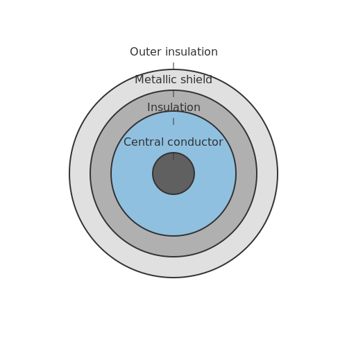
At their core, coaxial cables consist of a central conductor, usually made of copper, surrounded by an insulating layer, a metallic shield, and an outer insulating layer. This structure effectively reduces electromagnetic interference (EMI) and enables coaxial cables to carry high-frequency signals with minimal signal degradation. This characteristic makes them particularly well-suited for various telecommunications applications.
Signal Transmission Efficiency
One of the key advantages of coaxial cables lies in their capacity for efficient signal transmission. Due to their construction, they exhibit a low attenuation characteristic, which is particularly beneficial for long-distance communication. The power loss incurred during transmission is reduced, thereby extending the distance over which data can travel without significant degradation. This is critical in scenarios such as:
- Television and satellite broadcasts: Coaxial cables are extensively used to connect receivers to satellite dishes, providing high-quality video and audio signals.
- Internet access: Many ISPs utilize coaxial cables in hybrid fiber-coaxial (HFC) networks to deliver broadband services.
The high bandwidth capabilities of coaxial cables enable them to support multiple channels of data without interference, making them ideal for cable television and data services. Furthermore, the shielding provided by the metallic layers protects the signal from external noise, enhancing the overall signal-to-noise ratio (SNR).
Standards and Characteristics
Coaxial cables are typically defined by specific standards, including RG (Radio Guide) ratings. Some common RG types include RG-6 and RG-59, each designed for different applications, with RG-6 being favored for digital cable and satellite signals due to its lower loss at higher frequencies. When evaluating coaxial cables for telecommunications use, several characteristics must be considered:
- Impedance: Standard coaxial cables have an impedance of either 75 ohms (for video applications) or 50 ohms (for radio frequency applications). Selection is crucial as mismatched impedance can lead to signal reflections and loss.
- Dielectric material: The material used as insulation impacts the cable's performance, particularly at high frequencies. Low-loss dielectrics, such as foamed polyethylene, are preferred for enhanced performance.
- Frequency range: Different coaxial cables are suitable for varying frequency ranges, which affects their application in telecommunications. Higher frequency cables can carry more data but may be subject to increased losses.
Real-World Application
In recent years, the rise of digital telecommunications has showcased the performance of coaxial cables in supporting robust data services. Advancements such as DOCSIS (Data Over Cable Service Interface Specification) leverage these characteristics, enabling high-speed internet access over coaxial connections. The capability to handle higher frequency signals seamlessly translates to enhanced data transmission rates, paving the way for technologies such as:
- Video on demand (VOD): Consumers can stream high-definition content thanks to the bandwidth capabilities of combined coaxial and fiber optic networks.
- IP Telephony: Voice-over-IP services utilize coaxial cables to transmit data packets effectively, ensuring call clarity and reliability.
As we continue to move into an era dominated by data and high-speed communications, the role of coaxial cables in telecommunications remains pertinent. Their efficiency, coupled with advancements in cable technology, assures that they will remain a crucial component of modern networking solutions.
4.2 Applications in Broadcasting
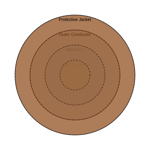
Coaxial cables have become integral to broadcasting systems, owing to their unique physical structure and electrical characteristics. In broadcasting, signals must travel long distances without significant attenuation or distortion, a challenge that coaxial cables are specifically designed to meet. Their construction, typically comprising an inner conductor, insulating dielectric, an outer conductor, and a protective jacket, ensures excellent signal integrity by minimising external interference and maintaining a uniform impedance.
The Role of Coaxial Cables in Television Broadcasting
In traditional television broadcasting, coaxial cables transmit both analog and digital signals from broadcasting stations to consumers. The required bandwidth, high-frequency capabilities, and low-loss transmission properties of coaxial cables make them ideal for this application. The characteristic impedance of commonly used coaxial cables—50 ohms for radio frequency applications and 75 ohms for video applications—ensures optimal performance for the intended use.
For example, in a system transmitting Ethernet data, such as a coaxial-based cable modem, the standards specify the connection must work effectively within a spectrum that allows for both upstream and downstream data. The low attenuation of high-quality coaxial cables facilitates multi-channel data transmission, enabling multiple television channels to be sent over the same line.
RF Broadcasting Systems
Coaxial cables are also pivotal in radio frequency (RF) broadcasting systems. The high-frequency signals transmitted in these systems require a medium that can efficiently propagate signals across considerable distances. Here, the coaxial cable's shield serves to safeguard sensitive RF signals from external electromagnetic interference (EMI), a characteristic crucial for preserving audio fidelity in FM radio or clarity in signal reception for AM radio.
Loss Characteristics and Material Considerations
The electrical performance of coaxial cables in broadcasting applications is heavily influenced by their materials and construction. For instance, the dielectric material used between the inner and outer conductors plays a significant role in determining the cable's attenuation characteristics. Common materials include polyethylene, which offers low dielectric losses, and foamed polyethylene, which can achieve even lower losses due to its reduced density.
The attenuation \(A\) of a coaxial cable, expressed in decibels per unit length, can be derived from both the material properties and the signal frequency. The formula for attenuation is given by:
Where:
- A is the attenuation in dB.
- R is the resistive loss in ohms per unit length.
- Z_0 is the characteristic impedance.
- \alpha represents other losses, such as dielectric and radiation losses.
To ensure optimal performance, engineers must consider not only the cable characteristics but also environmental factors, such as temperature and humidity, that may impact signal integrity.
Trends and Future Directions in Coaxial Applications
As broadcasting technology advances, particularly with the transition to digital and high-definition signals, innovations in coaxial cable construction and materials are augmenting performance and reliability. The increasing demand for higher bandwidth capabilities, such as those required for 4K and 8K video, is pushing the limits of coaxial cable technology.
Emerging designs include the use of advanced dielectric materials and multi-conductor configurations to further enhance performance. Additionally, as wireless broadcasting becomes more prevalent, coaxial cables are being adapted to bridge the gap between traditional wired systems and emerging wireless technologies, ensuring a cohesive transition in broadcasting capabilities.
In summary, the extensive use of coaxial cables in broadcasting systems illustrates their indispensable role in ensuring signal integrity over long distances while adapting to the changing demands of modern technology.
4.3 Role in Satellite Communication
Coaxial cables play a crucial role in satellite communication systems, serving as a primary medium for transmitting RF signals from ground stations to satellites in orbit and vice versa. The fundamental design of a coaxial cable enables it to maintain signal integrity over long distances, which is essential for the reliability and efficiency of communication links.
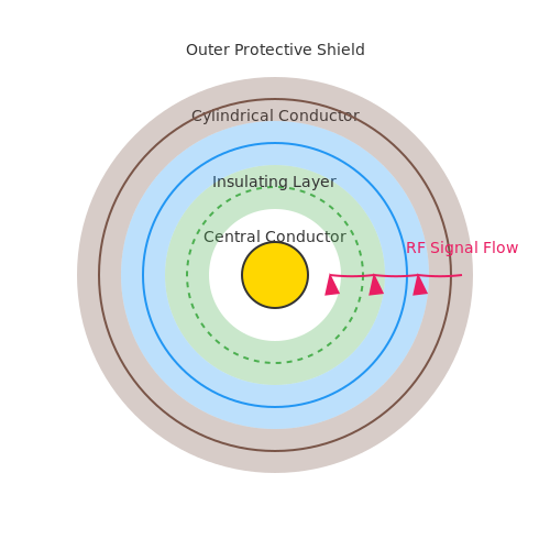
One of the primary characteristics that make coaxial cables suitable for satellite communications is their ability to minimize signal loss. The design includes a central conductor, an insulating layer, a cylindrical conductor, and an outer protective shield. This configuration helps in reducing electromagnetic interference (EMI) and maintaining a consistent impedance, typically 50 or 75 ohms, tailored to the specific communication needs.
Signal Integrity and Radiation Loss
Signal integrity is critical in satellite communications, where data must travel vast distances. The coaxial design provides a pathway that is both well-defined and protected from environmental factors, substantially reducing signal attenuation compared to other types of cables. The insulation serves not only to separate the conductors but also to prevent signal radiation into the environment.
In this formula, A represents attenuation in decibels (dB), V_{in} is the input voltage, and V_{out} is the output voltage. A lower attenuation value indicates a more effective cable design, thus benefiting satellite communication systems.
Coaxial cables are also relatively lightweight, which is valuable in satellite systems where weight constraints are significant. The less a satellite weighs, the more efficient it can be in terms of launch costs and fuel consumption. This advantage pairs well with the rugged durability of coaxial design, making it a preferred choice in harsh space environments.
Real-World Applications
The integration of coaxial cables in satellite communication can be seen in numerous applications, including:
- Broadcasting: Television and radio signals are transmitted via satellites using coaxial cables to deliver content directly to consumers.
- Internet Services: Satellite internet providers use coaxial cables to connect ground stations with orbital satellites offering high-speed data transmission.
- Military Communications: Military satellites rely on coaxial technology for secure and reliable communication, often in remote locations.
As we transition into an era of growing data demands and advanced satellite technologies, understanding the role of coaxial cables will remain paramount. Their advantages in maintaining signal quality, reliability in transmission, and adaptability to varied environments confirm the enduring significance of this technology in the realm of satellite communication.
5. Tools for Testing Cable Performance
5.1 Tools for Testing Cable Performance
In the realm of coaxial cable applications—spanning telecommunications, broadcasting, and data networking—the ability to accurately assess cable performance is paramount. Engineers and researchers rely on an arsenal of testing tools designed to evaluate various aspects of coaxial cables, such as attenuation, signal integrity, and impedance characteristics. Understanding the functionalities and limitations of these tools enables more informed decisions throughout the design, installation, and maintenance phases of coaxial systems.Cable Loss Testers
Cable loss testers are critical instruments for quantifying the attenuation of a coaxial cable. Attenuation is defined as the reduction in signal strength as it travels through the cable, typically expressed in decibels per unit length (dB/m or dB/ft). A common equation used in this context is:Time-Domain Reflectometers (TDR)
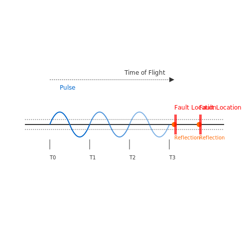
Time-domain reflectometry (TDR) is another sophisticated tool utilized for coaxial cable testing. TDR works by sending a pulse down the cable and observing the reflections caused by impedance discontinuities, such as connectors and defects. This method can precisely identify the location and type of faults along the cable length. The principle behind TDR can be summarized by the following equation that expresses the distance to a fault:Vector Network Analyzers (VNAs)
Vector Network Analyzers (VNAs) play a crucial role in characterizing coaxial cables, providing measurements of reflection and transmission coefficients across a range of frequencies. These measurements are essential for determining the impedance characteristics of the cable and evaluating how they affect signal integrity. The S-parameters (scattering parameters) are typically measured, where \( S_{11} \) represents the reflection coefficient:Summary of Key Testing Tools
In summary, various tools are indispensable for assessing coaxial cable performance, each serving unique functions tailored towards specific parameters of interest. The practical relevance of these tools cannot be overstated—they empower professionals to maintain effective coaxial communication systems and implement enhancements where necessary. To close this exploration, consider the following key tools:- Cable Loss Testers: Measure attenuation across the cable.
- TDR: Identify faults through reflection analysis.
- Vector Network Analyzers: Evaluate S-parameters for impedance matching.
5.2 Common Faults and Troubleshooting
The integrity of coaxial cables is crucial for reliable data and video transmission across various applications in telecommunications, broadcasting, and networking. However, like all electronic components, coaxial cables are prone to faults that can significantly degrade performance. Understanding these common issues and their solutions is essential for engineers, technicians, and researchers in the field.
Faults in Coaxial Cables
Coaxial cables can encounter several types of faults, including:
- Impedance Mismatch: This occurs when there is a difference in impedance between components in the transmission line, leading to reflections that can cause signal degradation.
- Signal Attenuation: As signals travel through the coaxial cable, loss due to resistance in the conductive materials, dielectric losses, and others may occur, resulting in weakened signals.
- Connector Faults: Poorly made or damaged connections at either end of the coaxial cable can lead to intermittent or complete signal loss.
- Cable Damage: Physical damage to the cable, such as kinks, cuts, or crushing, can alter its electrical properties and affect performance.
- Environmental Factors: Exposure to extreme temperatures, humidity, and other environmental conditions can influence the performance and lifespan of coaxial cables.
Troubleshooting Techniques
Successful troubleshooting begins with a systematic approach to identifying and resolving faults in coaxial cables. Here are several strategies that can be effectively applied:
Visual Inspection
Begin with a thorough visual inspection of the coaxial cable and connectors. Look for:
- Obvious physical damage, such as cuts or abrasions.
- Loose or corroded connectors.
- Signs of environmental wear, such as discoloration or swelling.
Recognizing such issues early can prevent unnecessary signal loss and performance degradation.
Impedance Measurement
To check for impedance mismatch, use an impedance analyzer or a vector network analyzer (VNA). This measurement process typically involves:
- Connect the measurement device to the cable ends.
- Use the device interface to measure the impedance at different points of the cable.
If the measured impedance does not align with the expected nominal values (e.g., 50Ω for RF applications), adjustments or replacements may be necessary.
Signal Loss Assessment
To evaluate signal attenuation, perform a known signal transmission experiment:
- Send a test signal through the cable while monitoring the output at the opposite end.
- Compare the input and output signal levels using an oscilloscope or a signal analyzer.
Using the formula for attenuation, expressed in decibels (dB), helps quantify the signal loss:
Where \( P_{in} \) is the input power and \( P_{out} \) is the output power. An excessively high value indicates problems such as signal leaks or excessive loss due to cable or connector faults.
Connector Testing
Use a continuity tester or multimeter to ensure that there is a complete circuit through the coaxial connectors:
- Check for continuity between the center conductor and the corresponding point in the other connector.
- Ensure no short circuits between the center conductor and the shield.
Faulty connectors can often be replaced easily, restoring normal function without needing to replace the entire cable.
Conclusions
Identifying and troubleshooting common faults in coaxial cables is essential for maintaining robust, high-quality signal integrity in electronic systems. By employing visual inspection, impedance measurements, signal loss assessments, and connector testing, engineers and technicians can swiftly pinpoint issues and implement effective solutions.
This systematic approach not only enhances equipment reliability but also extends the operational lifespan of critical communication infrastructure.
5.3 Maintenance Best Practices
Understanding Coaxial Cable Degradation
The performance of coaxial cables can decline over time due to various factors including environmental influences, mechanical stress, and electrical wear. As advanced engineers or researchers, it is crucial to recognize that identifying and mitigating these degradation factors can greatly extend the life and performance of these cables. One major factor is moisture ingress, which can lead to signal attenuation and loss of shielding effectiveness. Moreover, physical impacts such as bending, crushing, or pulling can alter the electrical characteristics by changing the dielectric properties. An effective maintenance strategy aims to minimize these risks through proactive inspections and careful handling during installation and operation.Routine Inspection and Testing
Performing regular inspections is an essential aspect of coaxial cable maintenance. Each cable should be systematically evaluated for physical integrity and signal performance. Recognizing signs of damage, such as kinks, abrasion, or fraying, can prevent performance degradation. Testing tools like Time-Domain Reflectometers (TDR) can help pinpoint faults by accurately measuring the cable's impedance, allowing engineers to assess the cable's condition without physically accessing all areas. Signal integrity tests should be conducted at regular intervals, particularly in critical applications. Changes in signal strength or quality can be early indicators of possible failure. Anomalies detected in the frequency response or increased return loss may warrant immediate attention.Environmental Controls
Coaxial cables are sensitive to environmental conditions that could significantly affect their operation. They should be installed in suitable settings where temperature, humidity, and exposure to chemicals can be controlled. Overheating, due to high power levels or inadequate ventilation, can alter the physical properties of the cable insulation, resulting in diminished performance. Best Practices for Environmental Controls:- Ensure cables are rated for their intended operating temperature ranges.
- Use protective conduits in areas prone to chemical exposure or temperature fluctuations.
- Implement humidity control strategies in environments with high moisture levels.
Connector and Joint Maintenance
The interfaces where coaxial cables connect to devices or other cables are critical points of failure. Proper maintenance of connectors and joints can eliminate one of the most common spots for signal loss. Ensure all connectors are clean and free of corrosion. Corroded connectors can result in unreliable electrical connections, increasing attenuation and reflection. Connector Maintenance Best Practices:- Inspect and clean connectors regularly with suitable contact cleaners.
- Utilize torque settings specified by manufacturers when tightening connections to avoid mechanical damage.
- Replace any connectors that exhibit significant wear or resistance.
Documenting Maintenance Activities
Finally, maintaining a detailed record of all maintenance activities is paramount. This documentation allows for trend analysis over time, which can highlight reoccurring issues or areas requiring specific focus in the future. By equipping teams with the ability to review past maintenance, informed decisions can be made about future upgrades, replacements, and interventions. In summary, proactive maintenance of coaxial cables—through regular inspections, environmental controls, joint integrity checks, and comprehensive documentation—can greatly enhance performance and lifespan, thereby reducing overall operational costs in the long term. By adopting these practices, you can ensure that coaxial cables operate reliably within their intended applications, whether in telecommunications, broadcast systems, or high-frequency data transfer solutions.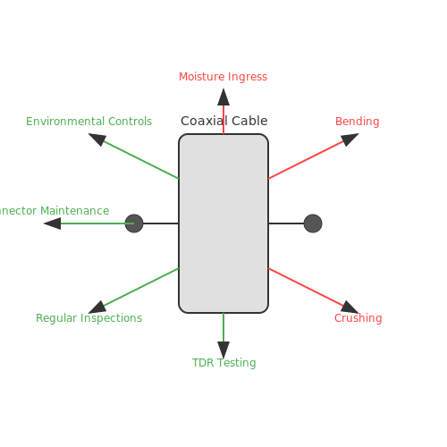
6. Textbooks and Reference Guides
6.1 Textbooks and Reference Guides
- Coaxial Circuits by T.C. Carlton — This book offers a comprehensive introduction to the principles of coaxial circuits, including detailed theoretical explanations and practical examples for RF and microwave engineering.
- Microwave Engineering by David M. Pozar — An essential textbook providing deep insights into microwave engineering, including in-depth sections on transmission lines, which feature detailed discussions of coaxial cable properties and applications.
- Coaxial Cables and Waveguides — This resource focuses on the theory and practical aspects of coaxial cables and waveguides, making it an invaluable reference for engineers working with high-frequency applications.
- Transmission Line Design Handbook — This handbook covers the design considerations of transmission lines, including a profound section on coaxial cable design, microwave engineering, and RF circuit design techniques.
- LTE-Advanced: Evolution — While focused on LTE technologies, this text provides relevant details on the use of coaxial cables in supporting RF and microwave systems, as well as data transmission considerations.
- RF and Microwave Transmitter Design — This text elucidates the essential designs of RF and microwave transmitters. The focus on transmission lines includes an analysis of coaxial cables, offering valuable guidance for practical designs.
- Introduction to RF Coaxial Cable Design and Performance — This guide provides an overview of RF coaxial cable design and performance factors, exploring various cable configurations and their specific applications in high-frequency transmission.
- Microwave Transmission Line Circuits — A detailed IEEE eBook that covers essential concepts and practical techniques in designing microwave transmission lines, including in-depth insights on coaxial cables used in modern communication systems.
6.2 Technical Journals and Articles
- ScienceDirect: Circuits and Systems — This journal provides comprehensive coverage of research on electrical circuits and systems, including topics on coaxial cable design and application.
- IEEE Xplore: Coaxial Cable Engineering — Explore detailed studies on the engineering aspects of coaxial cables, including manufacturing techniques and performance analysis in various environments.
- SpringerLink: Analog Integrated Circuits and Signal Processing — Dive into advanced theories and practical applications of signal processing where coaxial cables play a crucial role in high-frequency data transmission.
- ScienceDirect: Journal of Electrical Systems and Information Technology — This publication presents innovative advances in electrical systems technologies, featuring research on coaxial cable properties and throughput optimization.
- Elsevier: International Journal of Electrical Power & Energy Systems — A resourceful journal for understanding the applications of coaxial cables in power transmission systems and how they influence energy efficiency.
- InderScience: International Journal of Electronic Transport and Reliability — Focuses on the reliability and transport aspects of electronics, including performance assessments of coaxial cable systems in challenging conditions.
- IET Digital Library: Science, Measurement & Technology — Provides peer-reviewed papers on scientific measurement technologies, often featuring insights into the testing and evaluation of coaxial cables in applied physics.
6.3 Online Resources and Tutorials
- Coaxial Cable Through the Ages — This CableLabs technical paper provides a comprehensive history and evolution of coaxial cable technology, from its inception to modern advancements in broadband delivery.
- A Complete Guide to Coaxial Cables — Explore this detailed guide to understand the different types of coaxial cables, their specifications, use cases, and the differences in quality and performance.
- The Broadcast Bridge - Coaxial Cable Characteristics Handbook — This handbook offers in-depth theoretical and practical insights into coaxial cable properties, including impedance, attenuation, and signal integrity, critical for broadcast applications.
- All About Circuits: Coaxial Cables in RF Applications — An informative article on how coaxial cables are employed in RF applications, highlighting key characteristics like shielding effectiveness and dielectric materials.
- Electronics Notes: Coaxial Cable Design & Specifications — This page provides detailed explanations of coaxial cable designs, technical specifications, and the impact of design choices on performance in different engineering applications.
- Radio World - Coaxial Cable Performance Guide — A guide highlighting performance metrics for coaxial cables, focusing on practical considerations for broadcasting and RF engineering professionals.
- Cabling Installation & Maintenance - Dielectric and Shielding in Coax Cables — This resource provides insight into the materials used in coaxial cables and their influence on cable performance, crucial for design engineers and installation technicians.