



Voltage-controlled-current-source-with-grounded-source-and-load
This is a simple, precise voltage-controlled current source. Bipolar supplies will permit bipolar output. Configurations featuring a grounded voltage- control...
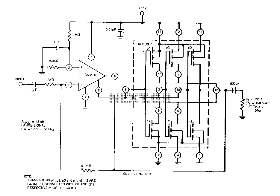
Output-stage-power-booster
This circuit easily supplements the current-sourcing and current-sinking capability of the CA3130 BiMOS op amp. ...

Balanced-modulator
This circuit passes the input signal at unity gain, either unchanged or inverted, depending on the digital control input. A buffered input is shown, since low-...

Operational-amplifiers
This is a single gain-of-100 amplifier with a gain-bandwidth product of 20 MHz! The primary limitation in the performance is the low slew rate (0.3 VIJ1s) impo...

High-q-notch-filter
This circuit shows a twin-T network connected to an LMl02 to fonn a high-Q, 60-Hz notch filter. The junction of R3 and C3 which is normally connected to ground...

Twin-t-notch-filter
This filter is used to reject or block a frequency or band of frequencies. These filters are often designed into audio and instrumentation systems to eliminate...

Analog-multiplexer-with-buffered-input-and-output
· This circuit is used for analog signal selection or time division multiplexing. As shown, the feedback signal places the selected amplifier channel in a v...

Modulator
Because the transconductance of an operational transconductance amplifier is directly proportionai to /ABc. the amplification of a signal can be controlled eas...

Universal-mixer-stage
This circuit illustrates some possible buffer combinations. Tbese include a differential input stage, a voltage follower as well as both noninverting and inver...

Output-limiter
HA-5190 is rated for ±5 V output swing, and saturates at ±7 V. As with most op amps, recovery from output saturation is slow compared to the amplifier"...

Precision-voltage-inverter
This circuit allows a reference to be inverted with 1 ppm accuracy, ...

Resettable integrator
The low Rds and high peak current capability ofthe DG419 makes it ideal for discharging an·integrator capacitor. A high logic input pulse disconnects the in...

Differential-instrumentation-amplifier
This circuit relies on extremely high input impedance for effective operation. The HA-5180 with its JFET input stage, performs well as a preamplifier. The st...
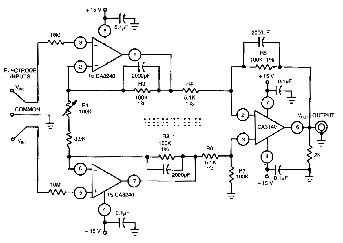
Biomedical-instrumentation-differential-amplifier
This differential amplifier uses the isolated high-impedance inputs of the CA3420 BiMOS op amp. ...

Wideband-instrumentation-amplifier
Has an input resistance of 1-MO, a bandwidth from de to about 35 MHz, and a gain of 10 times. Lowfrequency gain is provided by a CA3130 BiMOS op amp operated a...

Instrumentation-amplifier
LTC1043 and LT1013 dual op amps are used to create a dual instrumentation amplifier using just two packages. A single DPDT section converts the differential in...

Ultra-precision-instrumentation-amplifier
This circuit will run from a single 5 V power supply. The LTC1043 switched-capacitor instrumentation building block provides a differential-to-single-ended tra...

28Db-noninverting-amplifier
The physical circuit layout is extremely critical. Breadboarding is not recommended. ...

Frequency-to-voltage-converter
Six components can configure a circuit whose output voltage is proportional to its input frequency. The average current (hvc from the 40106 Schmitt trigger i...

State-variable-active-filter
A generalized circuit diagram of the two-pole state-variable active filter is shown. The state-variable filter can be inverting or noninverting and can simulta...