



Voltage-controlled-filter
The control voltage Vc easily sets the cutoff frequency w0 of this state-variable filter to any desired value, from about 1.7 MHz up to 5 MHz, with a BB 204 ...

Programmable-active-filters
This is a second-order, low-pass filter with programmable cutoff frequency. This circuit should be driven from a low-source impedance since there are paths fro...

Positive-peak-detector
This peak detector uses a CA3100 BiMOS op amp as a wide-band noninverting amplifier to provide essentially constant gain for a wide range of input frequencies....

Wide-bandwidth-peak-detector
This circuit can detect the positive peaks for signal frequencies higher than 5 MHz. It yields ±1% accuracy for 400 mV to 4 V pk-pk signal amplitudes on sin...
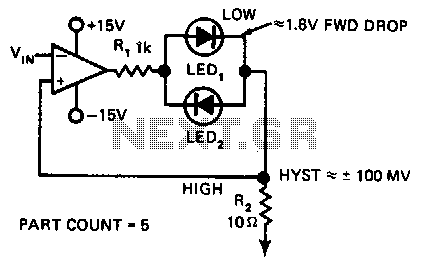
Null-detector
In this indicating comparator circuit, R2 sets the hysteresis. If the 741 saturates at ± 12 V, the current in R1 will be approximately ± 10 mA if 0.1 V...

High-bandwidth-peak-detector
The high-speed peak detector uses a highly accurate, fast s/h amplifier controlled by a highspeed comparator. The s/h amplifier holds the peak voltage, until...

Precision-threshold-detector
This circuit requires low noise, low and stable offset voltages, high open loop gain, and high speed. These requirements are met by the HA514 7. The standard...
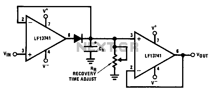
Low-drift-peak-detector
This circuit uses op amp Ul to compensate for the offset in peak detector diode Dl. Across c. is the exact peak voltage; ...

Precision-envelope-detector
This circuit is useful for signal-processing sonar data recorded on an instrumentation-quality analog tape recorder. The envelope detector utilizes ready avail...

Wide-range-peak-detector
ICl and IC2 form an inverting half-wave precision-rectifier/peak-detector circuit. Negative input-signal, swings with peaks larger than the voltage on Cl, caus...

Voltage-ratio-to-frequency-converter
The circuit accepts two positive-voltage inputs VN and Vv and provides a TTL-compatible output pulse train whose repetition mte is proportional to the ratio VN...

Low-voltage-compander
The NE575 is a dual-gain control circuit designed for low voltage applications. The NE575"s channell is an expander, while channel2 can be configured either fo...

Four-channel-comparator
When operated as an open loop without compensation, the HA-2400 becomes a comparator with four selectable input channels. The clamping network at the compensat...

Window-comparator
This window comparator generates an output pulse for each event that occurs within a specified window. That is, each output pulse signifies an input voltage pu...

Dual-limit-microvolt-comparator
When the upper or lower limit is exceeded, the LED lights up. Positive feedback to one of the nulling terminals creates 5 to 20 p,V of hysteresis on both amp...

Frequency-detecting-comparator
A quad comparator forms the basis of a frequency detector that is faster and less expensive than more complex versions designed around frequency-to-voltage con...

Comparator-latch
The primary advantage of this circuit, when compared to other comparators, is its ability to latch after the input has reached a predetermined threshold level. ...

Microvolt-comparator-with-hysteresis
Positive feedback to one of the nulling terminals creates approximately 5 p.V of hysteresis. The output can sink 16 mA; ...

Window-comparator
A window detector is a specialized comparator circuit designed to detect the presence of a voltage between two prescribed limits; that is, within a voltage win...

Accurate-variable-gain-circuit
The circuit can use any general-purpose, low-offset, low-drift op amp, such as the OP-07. The differential signal from the bridge feeds an amplifier that drive...